Note: Descriptions are shown in the official language in which they were submitted.
20~733~
A ~ETHOD FOR ELEC?ROC~EMICALLY TP~A~I~G
~ATTERY PLATE STOCX AND RELATED PRODUCT
~0rJ2~ .IVE~ C~.
1. Field of Invention
.
This invention relates to an improved ~e~noa or
eiectrochemicaily treating electrodes ~Ised n tne .~anuLac~u~-
of lead-acid batteries and an associated product. ~ore
specificaily, the invention relates to a metnod o.
~lectrochemically f~rming lead-acid batt~r~ pla.e ~.~c~
configurations which can be utilized to autcmate the battery
production process.
2. ~escription of .he Prior ~r_
The lead-acid battery is well ~nown as a
rechargeable power source for automotive starting, standby
power, vehicular traction, emergency lighting, powering
portable tools and appliances, and many otner applications
requiring a remote and renewable source of electricity.
Regardless of application, the conventional battery generally
consists of a plurality of positive and negative electrodes
which are electrically insulated from one another by a porous
separator and immersed in a sulfuric acid electrolyte. The
electrodes may be in the form of flat plates, tubes, rods, or
spiral-wrapped sheet or strip, or combinations thereof. ~he
vast majority of lead-acid batteries contain flat positive
plates and flat negative plates which are made by applying a
leady oxide paste to a grid structure made of lead or a lead
alloy.
'
,
:, ,
20~7 33f~
Worldwide, hundreds of ~illions of rlat-plate lead-
acid batteries of all types are producea. ~s each unit
contains a multitude of battery plates, even a moderatelv-
s:zed man~facturer must produce and handle tens of ~illion~
o- plates per year, eacn containing lead-basea compounds
whicA ~resent a ~otential hazard. .~s a resu ! . ,at_er
producers are at~empting to automate tne manufac~rir,g
process in order to reduce costs and minimize worker
exposure.
The proc~ss of l~aking a lat l~ad-acld ~ er-,-
2`ate having suitable electrochemical characteristlcs
involves the steps of (l) applying a layer of a paste
(normally containing a mixture of leady oxide, sulfuric acid
and water) to a lead-based grid structure c~ntai~ins a
reticulated grid portion and a ~rid border por~ion or
portions; (2) curing the resulting pasted plate in order to
(i) convert any free lead to lead oxide, (ii) ger.erate a lead
sulfate crystal structure which optimizes plate performance,
(iii) strengthen the interface between the paste and the
grid, and (iv~ improve the overall strength of the plate; and
(3~ electrochemically forming the plate in order to convert
the active material on the positive plate to lead dioxide and
to convert the active material on the negative plate to
sponge lead, thereby yielding the compositions and structures
required for the efficient generation of power when the
plates are brought into contact with the sulfuric acid
electrolyte.
-The most common method of producing flat-plate
lead-acid battery plate stock involves casting lead-alloy
2 0 ~ r~ ~ 3 ~
grids using semi-eutomated permanen~ mold casting machines,
such as those marketed by the Wirtz Manufacturing Company.
The as-cast grid panel normally contains two grids,
altnough t ~ay consist of only one grid of a larger size or
a large number of grids of 3 smaller size.
~fter ~~imming, tne grid panel enters a oe;~
past ng machine, i~nic;~ inay be or a type s~c~ as ~.a~ ~ar~er~
by the MAC Engineering Company, in which the interstices of
tne grid are rilled with bat.ery paste.
- ~pon -xiting .he pas.er, .he ?as~ed ~r-d panel ._
passed through an oven in which it is flash dried. Curing of
the dried pasted plate stock is normally carried out in a
chamber equipped to provide control of temperature and
hum dity.
~lectrochemical formation of the cured battery
plate stock is normally achieved by either tank formation or
box formation. One known method of tank formation, described
in V.S. Paten~ 3,754,994, involves suspending double-plate
positive panels alternately with double-plate negative panels
in the forming acid in such a manner that, except for the
outer surfaces of the end plates, each pasted positive plate
surface faces, and is oriented essentially parallel to, a
pasted negative plate surface of approximately equivalent
surface area. All panels of the same polarity are
electrically connected in parallel. After formation, the
- formed battery plate stock is washed and dried, and the
double panel is then divided into individual plates which are
used in manufacturing the battery. This method involves
repeated handling of a very large number of individual
components at each step in the process and is costly,
.
I l -3-
~0~73'~
inefficient, and makes it diff cult to achieve desired
environmental control. Tank formation is also referred to as
the dry charge process.
The known alternative of box formation, versions of
which are described in U.S. Patent 4,081,899 and rJ.S. Patent
~,~0i,730, involJes constructi~q tne oatterv ~.cm -ur~
pla~es prior to for.~a~ion and 2errorming .;~e .ar~a~ ~n
process in the battery case. The finished battery is
generally constructed in a manner sucn that, excopt ~or ~he
outer surraces of the end plat~s, each past~d posi=i;e p-5
surface faces, and is essentially paralle1 to, a pasted
negative plate surface of approximately equivalent surface
area, so that the relative position of the positive and
negative battery plate stock during box formation ls the same
as that which occurs during tank formation. Acc~rdingly, box
formation, like tank formation, involves the undesirable
repeated handling of a very large number of plates prior to
being able to form the battery.
Recent developments in lead-acid battery
manufacture, such as the CQntinUOuS grid casting process
described in U.S. Patent 4,349,067 and U.S. Patent 4,415,016,
and the metal expansion process described in U.S. Patent
- 3,853,6~6, have made it possible to produce continuous
; lengths of battery grid stock which can be passed directly
into a continuous pasting machine, as described in U.S.
- Patent 4,271,586, or which can be coiled and stored prior to
being pasted. Regardless of the form in which the starting
stock enterfi the continuous paster, and although it is known
' to be possible to coil a continuous length of battery plate
stock as it exits the paster, as described in U.S. Patent
,~ .
l .
2~ 7~0
4,342,342, it is general DractiCe t~ cut the continuous
battery pl2te stock exiting the paster into individual plates
or plate doubles for subsequent curing and, if cured in coil
form, to cut the cured battery plate stock into plates to
faciiitate use in eitner the tank formation process and the
box ~ormation ?rocess. Dividing t;ne contlnuous ~a~ery plâ-?
stock at this point in the process results in .neL.icient
handling during formation which, in turn, prevents ef-ficient
automation of the cell assembly operation.
J.~. ~atent " 362,861 discloses a cei eons~Luc~:or.
and associated manufacturing method by which battery ?late
stock is box formed in a coiled configuration. The cell
described therein consists of a length of positive plate
stock, a length of negat ve plate stock, and a len~t:~ af
porous separator material juxtaposed between the two such
that the pasted surface of said length of positive plate
stock is opposed to the pasted surface of the negative plate
stock. The cell is prepared by coiling the three-piece
composite to form a "jelly-roll" structure which is placed in
a battery container and box formed. As in tank formation and
box formation of flat battery piates, this method involves
forming a configuration in which the pasted surface of a
positive plate faces, and is oriented generally parallel to,
the pasted surface of a negative plate of similar surface
area. Further, the method disclosed is applicable solely to
the production of small, single cells and results in a
structure in which the po:;itive ~nd negative plate stock are
intertwined with separator to form a three-piece composite.
; As such, this technique is not readily employable to produce
large coils of singular polarity.
-5-
. . .
2~ 733~
~one of these prior art Cormation techniques are
adapted for the formation of a large, "stand-alone" coil of
formed batte~y plate stock of singular polarity which is a
configuration desired for the high-speed, automated
production of lead-acid batteries. There remains, therefore,
a need for a practical method of ~anK fcrmation ~r con nuou~
lengths of battery plate StOCK in coil form wAich ~ouid
facilitate automated cell assembly and result in further
improvements in battery production economics, produc~
quality, and worker sacety.
SUMMARY OF INVENTION
- The present invention has met the hereinabove-
described need.
The invention provides a method for
electrochemically forming continuous lengths of battery plate
stock of singular polarity in coil form. The coil is
preferably configured in such a manner that the pasted
surfaces of adjacent laps are not in physical contact with
one another. The surfaces are separated from one another
sufficiently to form a channel that can receive forming acid
and through which gases generated during the formation
reaction can escape.
The method preferably involves electrochemically
forming the coil against an auxiliary electrode or a coil of
opposite polarity in such a manner that the surface of said
auxiliary electrode or coil of opposite polarity that is
closest to the coil undergoing formation is located generally
; .
. ' .
2 ~ ~ 17 ~
opposite an edge surface of sald coil being for~ed ~nd is
electrically insulated therefrom.
It is an object of the present invention ~ ?roviàe
a manufacturing process for the tank formation of continuous
lengths of battery plate s.~ck in coil ,~orm.
It is a further object or the invention .o make
formed battery plate stock in a configuration which
facilitates automation of the cell assembly process.
It is a further object of the invention .o pr~vide
1~ a means of reducing the cost of producing lead-acid batte.ios
and the environmental hazards inherent therein.
It is a further object of the invention to provide
formed plate stock of improved consistency and quality
relative to plate stock processed in the form of a multitude
of individual plates or plate doubles.
It is a further object of this invention to provide
a method of making a lead-acid battery of improved quality
and consistency.
It is a further object of this invention to provide
an electrochemically formed continuous length of battery
stock.
These and other objects of the invention will be
more fully understood from the following detailed description
of the invention on reference to the iIlustrations appended
hereto.
-
~ o ~ rt 3 3 ~
3RI~F DESCRIPTION OF T~E DRAWI~GS
Figure 1 is a fragmentary partially schematic ~ront
elevationa. view of pasted plate stock.
Figure 2 is a right side elevational view of the
piat~ stock of Figure 1.
Figure 3 is an end view of a coil of pasted ~late
stock.
Figure 4 is a front elevational view or the coil or
Figure 3.
Figure 5 is a schematic fragmentary expanaed view
of the coil of Figures 3 and 4.
Figure 6 illustrates schematically the use of an
auxiliary electrode in practicing one embodiment of the
method of this invention.
Figure 7 is a schematic illustration of a form of
electrical connection usable in the invention.
Figure 8 illustrates schematically the use of a
second coil in practicing a second embodiment of the method
of this invention.
Figure 9 and 10 are respectively schematic top plan
and front elevational views of a first experimental system.
Figures 11 and 12 are plots of discharge curves
showing voltage versus time for several test cells.
Figures 13 and 14 are respectively top and front
elevational views of a second experimental system.
Figure 15 is a plot of discharge curves showing
voltage plotted against time for a test cell prepared by
means of the second experimental system.
--8--
~ 7~3~
~ESCRIPTION OF ~HE PREFERRED EMBODIMENTS
Figures 1 through 5 illustrates the st~ucture and
configuration of the continuous length of battery piate stoc~
.hat ~ay ~e employed as the starting ~aterial ~or tsle me-nod
of tnis invention. In general, the expression "continuous
length of plate stock" as employed in describing the present
invention will refer to plate stock of surfic1ent size ~.a. a
pl~rality or ~at.ery 21ates may be o~tained thererrom ay
severing the stock at predetermined lengths. Tt will
generally be most advantageous to provide sufficient stock to
permit at least ten plates to be severed therefrom.
Referring more particularl~ to Figures l and 2, the
starting continuous length battery plate stock oonsists o,
layer of battery paste l (of a composition selected to
achieve the desired polarity of the plate stock after
formation) which has been applied to a continuous length of
battery grid strip 2. The grid strip 2 consists of a
reticulated grid portion 3, a lug portion 4, and a bottom
border portion 5. The lug portion 4 has side surfaces 6 and
an edge surface 7. The bottom border portion 5 consists of a
side surface 8 and an edge surface 9.
The paste layer l is applied to the entire surface
of the reticulated grid portion 3 and may extend in width
beyond both side surfaces of said reticulated grid portion as
a result of its being overpasted on both sides as shown in
Figure 2. In the alternative, the paste may be flush with
one of the side surfaces while extending be`yond the opposite
. _ 9 _
~I .
2~ 73~'3
surface (overpasted on one side); or be flush with both of
the side surfaces so as to be flush pasted.
~lost of the side surfaces ~ of the lug portion 4
are free of paste, although the paste layer may cover a s~all
portion of the side surfaces 10 disposed adjacent to the
region or connection with the lug portion 4 and tne
reticulated grid portion 3, as shown in Figure 2, to eî~ect
good electrical contact between said paste layer 1 and said
lug portion.
The lug portion 4 may be continuous and of cons~an.
width along the length of the grid strip 2, as shown in
Figure 1, or may consist of a top border portion 11 with a
number of plate lugs 12 projecting therefrom and spaced
periodically along the length of the continuous grid ~toc~,
lS as illustrated in the fragmented lines in Figure 1. The
thickness of the lug portion 4 may be greater than, equal to,
or less than the thickness of the paste layer 1 as desired.
It will be appreciated that the side surfaces 6 and the edge
surface 7 of the lug portion 4 would be generally free of
paste. The side surface 8 of the bottom border 5 may be
covered by the paste layer 1 or may be free of paste as
desired. It is preferred, however, that the edge surface 9
of said bottom border be substantially free of paste.
The number, size, shape, and pattern of the grid
wires making up the reticulated grid portion 3 may be of any
desired configuration suitable for use in the manufacture of
battery plates. The continuous battery grid strip 2 may be
produced by continuo~ls casting, metal expansion of as-cast or
wrought sheet, or by any other suitable process used for the
production battery grid stock in relatively continuous
1 --10--
20~73~v
form. All of these parameters will be well known to ~hose
skilled in the art.
Referring to Figures 3 through 5, the battery pla,e
stock to be electrochemically formed is configured in the
form of a coil 13 which has been wound in a manner such tAat
the surfaces 15, 16 (Fig. ~) of the paste iayer 1 of a~jacent
wraps are por.ions whicn are not in physical con~ac~ . cn~
another, thereby leaving a space 14 between wraps into which
Eorming acid can L-low and tArough wnich gases generated
during ,Ae forming operation can escape. The coil 13 ;~a~i~g
such spacing between adjacent wraps may be prepared by such
means, for example, as coiling loosely to leave a space
between wraps, coiling onto a surface containing a spiral
slot into which the continuous length of battery plate stock
can be fitted, coiling onto a surface containing protrusions
located in a spiral pattern around which the continuous
length of battery plate stock can be wrapped, providing a
plurality of spacer bars (oriented generally parallel to the
axis of rotation) around the circumference of each coil wrap
as said coil is wound, or by any other means which provides
the desired gap between the pasted surfaces 15, 16 of
adiacent wraps.
In another embodiment of the invention, the spacing
between the pasted surfaces lS, 16 of adjacent wraps may be
achieved by placing a layer of porous, acid absorbing
material of the desired thickness between adjacent wraps. In
this instance, the spacer material may contact part or all of
the surface area of the pasted surfaces 15, 16 of adjacent
wraps.
~0 ~ 73~,
In either embodiment of t~e invention, the s?ace
between the pasted surfaces 15, 16 of adjacent wraps must be
sufficient to permit an acid layer to be maintained between
the wr~ps during formation. The space may be on the average
about 0.005 to 1 inch with an average space of about 0.020 to
- 8.250 inch being preferred. T~e maximum space ~tween
adjacent wraps is controlled by the maximum size of tne coil
that can be handled and the total length of the battery plate
stock desired on each coil.
Electrochemical formation of such a coil lS
accomplished in a bath of sulfuric acid by forming against a
structure of opposite polarity. The coils of positive
polarity are converted ~o lead dioxide by the forming
operation and forming of the coils of negative polarity
converts the material to lead sponge. In one embodiment of
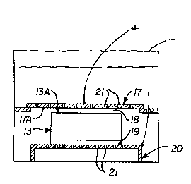
the invention shown in Figure 6, the coil 13 is formed
against an auxiliary (or dummy) electrode 17 of opposite
polarity positioned relative to said coil 13 such that the
surface 17A of said auxiliary electrode closest to said coil
is adjacent to an edge 13A of said coil and is electrically
insulated therefrom. It is preferred that the active surface
17A of the auxiliary electrode 17 will be positioned
- generally perpendicular to the pasted pLate surfaces 15 and
16 of the adjacent wraps of the coil 13, although formation
may still be achieved if perpendicularity is not attained.
Any means of achieving electrical insulation ~ay be used,
- including but not limited to a physical gap 18 betweenelectrode 17 and coil 13; or positioning a porous acid-
absorbing insulating separator between coil 13 and said
auxiliary electrode 17, so long as a layer of form~ng acid-
-12-
2 ~ 3
sufficient to carry the forming current is maintained between
said coil 13 and said auxiliary electrode 17.
The electrical connection to the coil 13 may
conveniently ~e made to the edge surface 7, or the sid~
surface 6 of the lug portion 4 (Figs. 2 and 6), or to tne
edge surLace 3 or side surface 8 of ..~e oottom ~order ~or~ion
of said coil (Fig. 2). Connection to the edge -~urLace , of
the lug portion 4 is preferred.
To improve the efficiency of formation and tne
uniformity of tne .^ormed battery plate s~oc~, it i~ pr~ferre~a
that the electrical connection between the coil 13 and the
formation power supply (not shown) be made at a number of
points l9A around the circumference of a wrap of the coil 13
(Fig. 7) and to a number of the individual wraps which,
collectively, make up the width of said coil l9B, as shown ir
Figure 7. The electrical connections may be made by
mechanical contact between said coil and an acid-resistant
electrical conductor or by attaching said acid-resistant
electrical conductor to said coil by welding, soldering, or
some other suitable means.
A preferred me~hod of attaining a uniform current
distribution throughout the coil 13 during forming is to
place the coil 13 in intimate contact with an electrically
conductive acid-resistant surface, such as that of an
electrically conductive pallet 20, shown in Figure 6, which
may also be used to support and convey the coil 13 during
processing. When coil 13 is positioned with either the
continuous lug portion 4 or the continuous bottom portion 5
in contact with the surface of said conduc ive pallet 20
most, if not all, of the wraps of said coil will be in
-13-
~ . . . . .
20~7~
contact with the conductive surface of said ~allet 20 around
all, or most, of the circumference of the individual wraps of
said coil 13. This extensive contact results in a generally
uniform current distribution throughout the coil 13. In the
case of a coil of a continuous length of battery plate stock
naving a top border ~ortion 11 and lugs 12 (Fig. i) spaced
periodically aiong the length or said oatter~ piate stocK,
the use of a conductive pallet would result in most, if not
all, of the lugs ~eing in intimat~ contact with the
conductive surface or said pallet. Tac~ welding, solcering,
or binding the coil 13 intimately to the pallet, for example,
are methods which may be used to reduce the electrical
resistance at the region of contact between the coil 13 and
the pallet 20. To improve acid circulation and electrical
efficiency, it is preferred that the electrically conductive -
pallet 20 and the auxiliary electrode 17 contain a plurality
of passages 21 through which acid can circulate. The
container in which the formation process is performed may be
constructed of any material that resists attack by sulfuric
acid, and is strong enough to support the weight of the acid
and the material being formed. These materials may, for
example, be polyvinyl chloride, reinforced epoxy,
polyethylene, and polypropylene. Other materials, as well as
the means of adding and removing acid, will be well known to
those skilled in the art.
Although it is preferred that the coil 13 and
auxiliary electrode 17 be positioned such that the axis of
the coil~ is generally vertical with the coil 13 positioned
beneath the auxiliary electrode 17 as shown in Figure 6,
formation may also be ~chieved with the coil 13 positioned
; -14-
2~i7~
above the auxiliary electrode 17 or ~ith the coil 13 dis2osed
in spaced relationship or between two auxiliary electrodes of
the same polarity. The pallets 20 and electrodes may be made
of any electrically conductive material which resists attack
by sulfuric acid such as, lead and lead alloys, and titanium
and titanium alloys, for example.
Ln anotner embodiment of the invention, shown .n
Figure 8, one coil 13 of continuous battery plate stock can
- be formed against a second coil 13D of continuous battery
plate stock of opposite polarity. In tnis embodiment, the
coils 13, 13D are positioned "edge-to-edge" with the axis of
one coil generally parallel to or aligned with the axis of
the opposing coil and an edge of one coil opposite an edge of
the opposing coil. In the specific configura~ion shown in
Figure 8, a coil 13D of negative battery plate stock has been
positioned with its lug portion down beneath a coil 13 of
positive battery plate stock which has been positioned with
its lug portion up, the coil 13D of negative battery plate
stock 15 in intimate contact with the surface of an
electrically conductive pallet 20A connected to the negative
terminal of the formation power supply ~not shown). The
spacing between coils 13 and 13D is preferably about 0.010 to
1 inch measured from coil edge to coil edge, and coil 13 of
positive battery plate stock is in intimate contact with the
surface of a conductive pallet 20B connected to the positive
terminal of the formation power supply. The power supply may
be any one of a number of commercially available units such
as tbose sold by Bitrode corporation which supply the amount
of D.C. current reguired to complete the formation reaction
in the desired period of time.
-15-
~0l7~a
Figure 8 shows the coil li of positive plate stock
supported by a non-conducting plate or lattice structure 21
which contains a plurality of openings 22 to facilitate acid
circulation and which, in turn, is supported by an annular
shelf of the forming tank 23. The electrically conducting
pallets 20A, 20B ~lso _ontain openings which facilitate ~cid
circulation through the pallets 20A, 20B and aiong .ne
passages resulting from the spaces between adjacent wraps of
both coils 13, 13D. Formation is achieved by passing tAe
desired amount of direct current througn the -ircui' for the
required a~ount of time at a temperature selected to optimize
efficiency and product quality. Typically, a coil containing
500 pounds of positive active material being formed at 185
ampere hours per pound for a period of 48 hours at a
temperature in the range of 110F-120F requires an averaye
current of 1,920 amperes. Upon completion of formation and
removal from the formation tank, the coils 13, 13D may be
washed and dried using procedures that are well known to
those skilled in the art.
If desired two coils of the same polarity may be
positioned on opposi-te sides of a third coil of opposite
polarity in effecting formation in a manner otherwise
generally similar to that shown in Figure 8.
While for convenience the above discussion and
illustrations have made reference to specific configurations,
polarities, and conditions of formation, it will be apparent
to those skilled in the art that one may practice the
invention with the position oE the positive and negative
coils or electrode reversed and employing other
configurations and conditions.
" 16
~0i733 ;J
The following examples provide specific pceferr~d
practices in employing methods of this invention.
EXAMPLE 1
This example illustrates that satisfactory
S formation can be achieved wAen the battery pla'e stock oeing
formed is oriented such that one edge ol saia Datter~ place
stock is located opposite the active surface of the body
against which it is being electrochemically formed, a
configuration which is required for forming continuous
battery plate stock in coil form.
Referring to Figs. 9 and 10, sixteen individual as-
cured positive battery plates 24 were formed against 16 dummy
negative battery plates 25 in an edge-to-edge config-
uration. The positive plates, which measured approximately
lS 1.79" long X 1.26" high X 0.077" thick were made by applying
a standard positive industrial battery paste grade to grids
which had been cast from a standard lead-calcium grid alloyi
MF-903. The negative plates, which measured 1.79" long X
1.26" high X 0.067n thick, were made by applying a standard
industrial negative battery paste grade to the same grid
alloy. The positive plates each contained about 8.3 grams of
cured paste. The negative plates each contained about 7.4
grams of cured paste.
- The sixteen positive plates 24 were placed in
slotted fixtures 26, which positioned the p~ates generally
parallel to one another and spaced approximately 3/16" inch
;.
-17-
., .
~Qi~
apart as measured between closest surfaces. The plates 24
were positioned with the lug portion of each plate projecting
upwards and all of the plates 24 were electrically connected
in parallel by soldering a lead alloy wire 27 to the lu~ of
each plate. The wire 27 was connected to the positive
terminal of the rormation power supply. The plates 2~ -~ste5
on a plastic support 26A wnich is attached to fixtur~ 26.
The positive plates 24 were positioned above
similar slotted fixtures which held the sixteen du~my
negative plates 25 generally parallel to one another and
spaced approximately 3/16" inch apart. The lug portion of
the negative plates 25 projected in a downwards direction.
The negative plates 25 were electrically connected in
parallel by soldering a lead alloy wire 28 to the lug on each
plate 25. The wire 28 was connected to the negative terminal
of the formation power supply. The gap 29 between the
positive plates 24 and negative plates 25 was approximately
inch.
The plates 24, 25 were formed in a bath 30
containing approximately 3,000cc of 1.06 S.G. sulfuric acid
which was maintained at a temperature in the range of about
108 F and 122 F. Five pairs of positive and negative
plates were formed to a level of approximately 155 ampere-
hours/pound of positive paste, five pairs were formed to a
level of approximately 168 ampere-hours/pound of positive
paste, and six pairs were formed to a level of approximately
174 ampere-hours/pound of positive paste, using the formation
cycle shown in Table 1.
-18-
~01733'~f
TABLE 1
TIME (HOURS) AVERAGE FORMING CURRENT TOTAL AMP-HOURS
2.0 2.4
1.8 ~.7
1.3 4.9
1.7 3.8
0.5 1.4
14.3 1.2
0.3 0.8 4
FIRST 5 PAIRS OF PLATES ~MOVED
3.0 0.8
2.5 0.5 49.3
SECOND 5 PAIRS OF PLATES REMOVED
5.0 0.4 51.
REMAINING 6 PAIRS OF PLATES REMOVED
The plates so formed were washed using standard procedures
and dried for 18 hours in vacuum at a temperature of
approximately 90C (194F).
The positive plates 24 processed in acc~rdance ~i.h
the above procedure were combined with negative plates -~hich
had been tank formed using a more conventional procedure to
build sealed cells having a target capacity of 1.25 ampere-
hours when discharged at 5 amperes at the 15- minute rate.
Three cells were constructed, each incorporating four
positive plates (formed to the same level, as described
hereinabove), three negative plates, standard AGM fiberglass
mat separators, and 1.28 S.G. sulfuric acid as the
electrolyte. Each cell was placed on a float charged at
2.35V for approximately 36 hours prior to testing. The cells
were discharged at a constant current of 5 amperes, charged
under constant voltage conditions at 2.38V for approximately
ll hours and then cycled using the same discharge current and
charging regime in accordance with a standard cycle test
regime employed in testing cells of this type.
~ u ~
The results of the capacity and cycle tests,
illustrated as discharge voltage versus time in minutes for
the first discharge cycle and ninth discharge cycle are shown
in Figures 11 and 12 cespec~:ively, Figure 11 shows that the
cell (CF-3) formed to a level of 174 ampere-hours/pound
attained the target capacity on i~s initiai discnarge ~ycie
and ?igure 12 shows that both of the other cells reacned
target capacity within the nine cycles. All cells continued
to gain in capacity with repeated cycling, with the celi (~F-
2) containing plates formed to a level of 168 ampere-
hours/pound reaching a capacity of 2.0 ampere-hours at the
twentieth cycle. These data illustrate that lead-acid
battery plate stock, formed in accordance with the method of
this invention, attain the desired capacity level and were of
excellent quality.
EXAMPLE 2
This example illustrat~s that satisfactory
formation can be achieved in continuous lengths of battery
plate stock in coil form and that a coil of continuous
positive battery plate stock can be formed against a coil of
continuous negative battery plate stock when the coils are
juxtaposed edge-to-edge.
Two concentric squares of positive plate stock,
positioned to maintain a physical gap between adjacent pasted
surfaces and connected electrically in parallel in order to
simulate two adjacent wraps of a coil of continuous positive
batt~ry plate stock having a space between wraps, were formed
, , .
-20-
?~---
~ 7X~
against two concentric squares of negative plate stock of
similar configuration and electrical connection intended to
simulate two adjacent wraps of a coil of continuous negative
battery plate stock having a space betweer.-wraps, as
illustrated in Figures 13 and 14. The siGes of the outside
squares 31 measured aporoximately 3.6" inch and eacn slde
contained two rull 1.79" long X 1.26" nigh battery platas.
The four sides of each outside square were connected
electrically by lead 32 and the outslde square was
electrically connected in parallel to the inside square ~_
the same polarity by connectors 33. The sides of the inside
squares measured approximately 3.4" inch and each contained
one full-size battery plate. The four sides of each inside
square were also connected electrically. The gap 34 between
the inside and outside squares was maintained at
approximately 0.030 inch- 0.060 inchO The thickness of the
positive plate stock 35 was 0.077" inch. The thickness of
the negative plate stock 36 used was 0.067" inch. The total
weight of positive active material in the assembly was
approximately 127 grams. The total weight of negative active
material in the assembly was 117 grams. The gap 37 between
the squares of positive polarity and the squares of negative
polarity was approximately 1/8" inch.
The simulated coils were formed to a level of
approximately 185 ampere-hours/pound in bath 38 of 1.06 S.G.
sulfuric acid maintained in the temperature range of about
112F to 118F Formation was carried over a period of 29.3
hours in accordance with Table 2.
.
-21-
~ ~ ''`'"~.~
~0 ~ 73~
TABLE 2
Average Forming Current
Time (Hours) Amperes
2.25 2.08
3.00 5.92
1.12 5.00
0.45 2.~3
0.25 1.52
22.25 0.96
After formation, the simulated coils were washed
using standard procedures and dried in vacuum for 18 hours at
approximately 90 C (194F). After drying, positive battery
plates cut from the positive plate stock were combined with
negative plates cut from the negative plate stock to form a
lS single cell. The cell contained four posi~ive plates and
three negative plates formed in accordance with the method of
this invention. The construction of the test cell was
basically the same as' that described in Example 1. The cell
was given a 17-hour booster charge at 2.4; volts before
testing and then cycled using a 5-ampere discharge to a 1.50V
cut-off followed by charging for approximately 7.1 hours at a
constant voltage of 2.45 volts.
As can be seen from the test results illustrated in
Figure 15 the cell containing plates formed in accordance
with the method of this invention attained the desired
capacity on its first discharge and continued to lncrease in
capacity with subsequent cycling. These data confirm that
the method of this invention may be used to produce high
quality coils of continuous battery piate stock of a single
polarity.
;, -22-
.-.,
20~7 J'~ ~
The coils of positive battery ?late stock and
negative battery plate stock produced in accordance with tne
method of this invention may be used as feedstock for the
automated pro~uction of lead-acid batteries and cells. In
machinery of this type, the coil stock is fed into a cutting
device in which it is cut to the battery plate si4e
required. The cut plate is transported automatical;y into
the cell making portions of the machine in which it is
alternately stacked with separators and plates of opposite
polarity to form a cell of the desired configuration and
capacity.
It will be appreciated that the method of this
invention provides an efficient means for forming battery
electrode stock in coil form in a manner which is consistent
with use in an automated system for battery production and
the resultant product.
It will be appreciated that while for convenience
of disclosure herein reference has been made to a continuous
length of battery plate stock in coil form other shapes and
arrangements will be apparent to those skilled in the art.
For example, an elongated strip having a series of folds
provided with spaces between adjacent portions may be
employed.
Whereas particular embodiments of the invention
have been described herein for purposes of illustration, it
will be evident to those skilled in the art that numerous
variations of the details may be made without departing from
the invention as defined in the appended claims.
! -23-
I' .