Language selection

Search

Patent 2017372 Summary

Third-party information liability

Some of the information on this Web page has been provided by external sources. The Government of Canada is not responsible for the accuracy, reliability or currency of the information supplied by external sources. Users wishing to rely upon this information should consult directly with the source of the information. Content provided by external sources is not subject to official languages, privacy and accessibility requirements.

Claims and Abstract availability

Any discrepancies in the text and image of the Claims and Abstract are due to differing posting times. Text of the Claims and Abstract are posted:

  • At the time the application is open to public inspection;
  • At the time of issue of the patent (grant).
(12) Patent: (11) CA 2017372
(54) English Title: PLUNGE JOINTER FOR PLANER KNIVES
(54) French Title: DRESSEUR DE CHANT POUR DEGAUCHISSEUSE
Status: Expired and beyond the Period of Reversal
Bibliographic Data
(51) International Patent Classification (IPC):
  • B27C 01/14 (2006.01)
  • B24B 03/36 (2006.01)
(72) Inventors :
  • JOHNSON, DAVID J. (United States of America)
  • GROGHAN, CHARLES L. (United States of America)
(73) Owners :
  • COASTAL MACHINERY COMPANY
(71) Applicants :
  • COASTAL MACHINERY COMPANY (United States of America)
(74) Agent: SMART & BIGGAR LP
(74) Associate agent:
(45) Issued: 1998-09-29
(22) Filed Date: 1990-05-23
(41) Open to Public Inspection: 1991-01-31
Examination requested: 1997-03-06
Availability of licence: N/A
Dedicated to the Public: N/A
(25) Language of filing: English

Patent Cooperation Treaty (PCT): No

(30) Application Priority Data:
Application No. Country/Territory Date
07/386,942 (United States of America) 1989-07-31

Abstracts

English Abstract


A base is arranged to be secured to the support frame of
a planer and supports a slide for movement toward and away
from the planer knife head. The slide supports a grinding
stone, and a lever connected between the base and the slide
is arranged to move the slide and the stone toward and away
from the knife head. The guard for the knife head on the
planer has an opening through which the present jointing
apparatus works. An adjustable stop is provided between the
jointer base and the slide to provide precision operation of
the slide and the stone in jointing operations.


French Abstract

Une base est conçue pour être assujettie au bâti support d'une raboteuse et comporte un coulisseau pour s'approcher et s'éloigner de la tête de coupe de la raboteuse. Le coulisseau porte une pière à aiguiser, et un levier raccordé entre la base et le coulisseau permet de déplacer le coulisseau et la pierre pour les approcher ou les éloigner de la tête de coupe. L'élément de protection de la tête de coupe de la raboteuse comporte une ouverture par laquelle travaille l'appareil de planage de la présente invention. Une butée réglable est placée entre la base de l'appareil de planage et le coulisseau pour assurer la précision de fonctionnement du coulisseau et de la pierre dans les opérations de planage.

Claims

Note: Claims are shown in the official language in which they were submitted.

1.
A knife jointing apparatus for planers of the type
having a support frame, a rotatably driven knife head,
and a guard wall adjacent the head, said apparatus
comprising:
a base member arranged to be secured to the support
frame on a side of the guard wall opposite from the knife
head,
slide means slidably mounted on said base member for
movement toward and away from the knife head,
a jointing stone on said slide means having a jointing
portion projecting from said slide means,
and lever means on said base member engageable with
said slide means and arranged to move said slide means and
stone toward and away from the knife head,
said lever means being arranged to move said slide means
past the guard wall for engagement of the jointing stone with
the knife head for jointing the knife head.
2.
The knife jointing apparatus of claim 1 wherein said
jointing stone is arranged to move through an opening in the
guard wall for engaging the knife head.
3.
The knife jointing apparatus of claim 2 including
adoor arranged normally to close said opening but to be opened
when said slide means and jointing stone are moved to joint

the knife head.
4.
In a planer apparatus:
a frame, a rotatable knife head on said frame,
a guard wall on said frame adjacent said knife head,
a base member arranged to be secured to said support
frame on a side of said guard wall opposite from said knife
head,
slide means slidably mounted on said base member for
movement toward and away from said knife head,
a jointing stone on said slide means having a jointing
portion projecting from said slide means,
and lever means on said base member engageable with said
slide means and arranged to move said slide means and stone
toward and away from said knife head,
said lever means being arranged to move said slide means
past said guard wall for engagement of the jointing stone
with the knife head for jointing the knife head.
5.
The planer apparatus of claim 4 including an opening in
said guard wall through which said jointing stone operates to
joint said knife head.
6.
The planer apparatus of claim 5 including a door
arranged normally to close said opening but to be opened when
said slide means and jointing stone are moved to joint the
knife head.

7.
The planer apparatus of claim 5 including a door
arranged normally to close said opening but to be opened
when said slide means and jointing stone are moved to
joint the knife head, and rest means on said door arranged
to hold it open in an elevated position or to allow it to
close by gravity.
8.
The planer apparatus of claim 4 including an adjusting
gauge stud on one of said base member and slide means and a
stop on the other of said base member and slide means
engageable by said gauge stud providing an adjustable
jointing position of said jointing stone.
9.
The planer apparatus of claim 4 including an adjusting
gauge stud on one of said base member and slide means and a
stop on the other of said base member and slide means
engageable by said gauge stud providing an adjustable jointing
position of said grinding stone, and means clamping said
jointing stone on said slide means for adjusted positioning
toward said grinding head.
10.
The planer apparatus of claim 4 wherein said slidable
mounting of said slide means on said base member comprises
an elongated dovetail connection therebetween, and slack
takeup means in said dovetail connection arranged to adjust
for wear therein.

Description

Note: Descriptions are shown in the official language in which they were submitted.


2~37~
P~UNGE JOIN~ER ~OR P~AN~R K~IV~
~ackground of the Invention
~his invention relates to new and useful improvements in
a plunge jointer for planer knives.
As is known in the trade, cutter head knives on planers
must be devoid of sharp corner edges in order that the~ will
perform a planing function efficiently. ~hus, jointers are
used to periodically shape the knives so that such corner
edges are removed. In current practice 7 when the planer
knives require jointing, the planer guard is first removed
and jointing apparatus bolted temporarily in place. ~uch
jointer is then operated for its intended purpose. In this
procedure, it is required that the planer be stopped during
-the time that the guard is removed and jointing carried out.
~his of course means down time which reduces the output
efficiency of the planer.
Summary of the Invention
According to the invention and forming a primary
objective thereof, a plunge jointer for planers is provided
which has improved structural features that allow the jointer
to be combined as a permanent part of a planer mechanism and
capable of performing its function without shutting down the
planer.
A more particular object of the invention is to provlde
a jointer mechanism o~ the type described having a novel
structure which is arranged to be combined with a planer
apparatus and capable of operating through the planer guard
wall whereby as noted, the planer does not have to be shut
:

3 ~ ~
down during operation of the jointer mechanism.
Other objects are to provide a jointer for planers th~t
is simplified in structure, inexpensive to manufacture, and
safe and efficient to operate.
In carrying out the above objects, the jointer mechanism
com~rises a base member secured to the support frame of a
planer and slidably supporting a jointer stone holding slide
for movement toward and away from the cutter head of the
planer. ~ever means are connected between the base member
and the slide for moving the latter and -the stone toward and
away from the cutter head. Planer apparatuses have a guard
wall adjacent the cutter head to protect personnel from
flying shavings, and according to the present invention the
jointer stone on the slide operates through an opening in
the guard wall for engaging the knives on the cutter head. A
slidable door is provided at this opening and is arranged to
be raised for allowing the stone to move through the guard
wall when jointing is being accomplished and to be returned
by gravity to a closed position when the stone is withdrawn.
A gauge stud is provided on the slide and is associated with
a stop on the base member whereby to provide adjustable,
precise jointing positions of the stone.
~ he invention will be better understood and additional
objects and advantages will become apparent from the follow-
ing description taken in connection with the accompanyingdrawings.

2~37~
~rief Description of the ~ra~,Jings
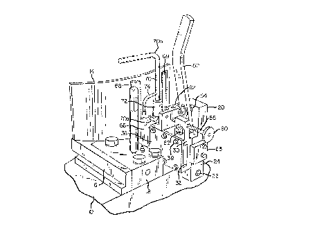
~ig. 1 is a rear perspective view of the present pllmge
jointer for planers, this view showing the door in the guard
wall in closed position and the stone retracted.
Fig. 2 is a view similar to Fig. 1 but showing the door
open and a forward grinding position of the stone.
~ig. 3 is a perspective view of the opposite side of the
guard wall from that shown in ~igs. 1 and 2.
~ig. 4 is an enlarged slde elevational view, partly
broken away and partly in section, of the present jointer.
Fig. 5 is a rear elevational view of the jointer
with portions thereof broken away; and
Fig. 6 is a fragmentary sectional view taken on the line
6-6 of Fig. 5.
Detailed Description of a Preferred ~mbodiment
Conventional lumber planer apparatuses comprise a frame
portion that supports one or more high speed cutter heads
with knives thereon. The cutter head operates behind a guard
wall on the frame. This guard wall has a removable wall
-section by means of which access can be had to the cutter
head for mounting and operating jointing apparatus on the
frame. ~Jith particular reference to the drawings, the
numeral 10 illustrates a conventional planer frame. A
portion of a cutter head having the usual knives 12 thereon
is shown in Figs. 4 and 6. The numeral 14 designates a guard
wall on the frame to protect personnel from flying planer
shavings. In conventional planers, this portion of the

2~ ~37~
guard wall is removable to provide access to the knives fsr
jointing. The numeral 16 designates a conventional lu~ber
guide fence mounted on a base 18 adjustably supported on ,,he
planer frame lO.
, ~he present jointer comprises an upstanding slide
support base member 20 secured to the planer frame by
suitable means such as by screws 22 extending through a
depending portion 24 of the base. One side of the base
member 20 has a front to rear dovetail slot 26, best seen in
~igs. 5 and 6, that slidably receives a correspondingly
,shaped projection 28 integral with a stone holding slide body
~0. A jointing stone 32 is clamped in a recess 34 in the
slide body 30 by a side plate 36 removably mounted in place
by a plurality of screws 38. Precision sliding movement o~
the slide base member 20 in the dovetail slot is maintained,
in the event of wear, by a gib plate 40 in one edge o~ the
slot 26 having adjustable engagement with an edge of the
dovetail projection 28 of the slide body 30 by one or more
set screws 42.
Slide body 30 has driving slidable movement toward the
kni~e head and return by an upstanding hand lever 50 with a
pivot connection 52 at its lower end to the slide body ana
having a pivotal lever support 54 above its lower end on the
base 20. ~he upper end of slide body 30 thraadedly supports
a horizontal front to rear slide gauge stud 58 having a hand
turning knob 60 thereon. Gauge stud 58 is associated
with a stop block 62 secured integrally to slide support base
20. ~y threaded adjustment of the stud 58 in the slide body

~7~72
~0, the association of such stud with the s~op block 62
facilitates precise inward movement of the slide body 30 an~
consequent precise movement of the stone into the knife head
for proper jointing. A plate 6~ is mounted on the rearward
portion of the base member 20 and has a portion thereof,
~ig. 6, in the path of the slide body 30 whereby to serve
as a rear stop for the slide body.
As pointed out hereinbefore, the guard 14 of existing
planers is removed for installing and operating jointer
equipment. The planer thus must be shut down. In the
present jointer mechanism, however, the slide support base 20
;is permanently installed on the frame 10 adjacent the base
18 of the guide fence 16 and the guard 14 is provided with an
opening 64 through which the stone can move and engage the
knives 12.
A door 66 is provided to close the opening 64 when the
present jointer is not in use. This door is slidably con-
fined for vertical movement in side guides 68 and has an
upwardly extending handle assembly 70 comprising a first
section 70a secured to the door and a second section
70b attached to the first section by means of a pivot
connector 72. Thus, handle section 70b can be rotated
relative to the cover. Handle section 70b has a
lateral rest finger 74 secured thereto arranged in a raised
position of the door and a rearwardly turned position of
the handle section 70b to rest on top of the guard wall 14
and hold the door open. The door will drop to its closed

3i~ ~
position by gra~ity when the handle section 70b is turned
forwardly and released.
According to the invention, the opening 66 is cut in
the guard wall l4 in alignment with the stone and as
determined by the mounted positioning of the base memb~r
20. The base member 20 is mounted permanently on the
planer frame, and when it is desired to joint the knife
head, it is merely necessary to op~n -the door 66 and
operate the jointer by opera~ion of the lever 50. The
guard wall 14 does not have to be removed and thus the
jointer can be operated while the planer is in full opera-
tion. Thus, there will be no down time and the planer can
run at full efficiency. ~y selected threaded adjustment of
the gauge stud 58, the slide body 30 and the stone can be
adjusted for wear of the stone or knives. The stone also
can be adjusted in the slide body by changing its clamped
longitudinal positioning in the slide body 30, thus utilizing
maximum length usage thereof.
It is to be understood -that the form of our invention
herein shown and described is to be taken as a preferred
example of the same and that various changes in the shape,
size and arrangement of parts may be resorted to without
depar~ing from the spirit of our invention, or tha scope of
the subjoined claims.
Having thus described our invention, we claim:

Representative Drawing
A single figure which represents the drawing illustrating the invention.
Administrative Status

2024-08-01:As part of the Next Generation Patents (NGP) transition, the Canadian Patents Database (CPD) now contains a more detailed Event History, which replicates the Event Log of our new back-office solution.

Please note that "Inactive:" events refers to events no longer in use in our new back-office solution.

For a clearer understanding of the status of the application/patent presented on this page, the site Disclaimer , as well as the definitions for Patent , Event History , Maintenance Fee  and Payment History  should be consulted.

Event History

Description Date
Inactive: IPC from MCD 2006-03-11
Time Limit for Reversal Expired 2003-05-23
Letter Sent 2002-05-23
Grant by Issuance 1998-09-29
Pre-grant 1998-03-11
Inactive: Final fee received 1998-03-11
Notice of Allowance is Issued 1997-10-17
Letter Sent 1997-10-17
Notice of Allowance is Issued 1997-10-17
Inactive: Status info is complete as of Log entry date 1997-10-14
Inactive: Application prosecuted on TS as of Log entry date 1997-10-14
Inactive: Approved for allowance (AFA) 1997-08-12
Classification Modified 1997-08-12
Inactive: IPC removed 1997-08-12
Inactive: First IPC assigned 1997-08-12
Inactive: IPC assigned 1997-08-12
All Requirements for Examination Determined Compliant 1997-03-06
Request for Examination Requirements Determined Compliant 1997-03-06
Application Published (Open to Public Inspection) 1991-01-31

Abandonment History

There is no abandonment history.

Maintenance Fee

The last payment was received on 1998-05-20

Note : If the full payment has not been received on or before the date indicated, a further fee may be required which may be one of the following

  • the reinstatement fee;
  • the late payment fee; or
  • additional fee to reverse deemed expiry.

Patent fees are adjusted on the 1st of January every year. The amounts above are the current amounts if received by December 31 of the current year.
Please refer to the CIPO Patent Fees web page to see all current fee amounts.

Fee History

Fee Type Anniversary Year Due Date Paid Date
Final fee - standard 1998-03-11
MF (application, 8th anniv.) - standard 08 1998-05-25 1998-05-20
MF (patent, 9th anniv.) - standard 1999-05-24 1999-04-26
MF (patent, 10th anniv.) - standard 2000-05-23 2000-04-17
MF (patent, 11th anniv.) - standard 2001-05-23 2001-04-20
Owners on Record

Note: Records showing the ownership history in alphabetical order.

Current Owners on Record
COASTAL MACHINERY COMPANY
Past Owners on Record
CHARLES L. GROGHAN
DAVID J. JOHNSON
Past Owners that do not appear in the "Owners on Record" listing will appear in other documentation within the application.
Documents

To view selected files, please enter reCAPTCHA code :


To view images, click a link in the Document Description column. To download the documents, select one or more checkboxes in the first column and then click the "Download Selected in PDF format (Zip Archive)" or the "Download Selected as Single PDF" button.

List of published and non-published patent-specific documents on the CPD .

If you have any difficulty accessing content, you can call the Client Service Centre at 1-866-997-1936 or send them an e-mail at CIPO Client Service Centre.


Document
Description 
Date
(yyyy-mm-dd) 
Number of pages   Size of Image (KB) 
Claims 1993-11-02 3 86
Abstract 1993-11-02 1 16
Description 1993-11-02 6 207
Drawings 1993-11-02 3 91
Representative drawing 1998-09-01 1 15
Commissioner's Notice - Application Found Allowable 1997-10-16 1 165
Maintenance Fee Notice 2002-06-19 1 177
Correspondence 1998-03-10 1 32
Fees 1998-05-19 1 41
Fees 1995-05-22 1 40
Fees 1997-05-19 1 52
Fees 1996-05-20 1 39
Fees 1993-05-13 1 27
Fees 1994-05-10 1 39
Fees 1992-03-02 1 26
Courtesy - Office Letter 1996-08-01 1 25
Prosecution correspondence 1997-03-05 1 44
Prosecution correspondence 1997-05-19 1 40