Note: Descriptions are shown in the official language in which they were submitted.
8 0
1 AKU 2189
APPARATUS FOR MAKING A TIGHTLY CLOSED LOOP
OF A TAPE OF THERMOPI~STIC MATERIAL AROUND AN OBJECT
BACKGROUND OF THE INVENTION
The invention relates to an apparatus similar to that
described in U.S. Patent Specification 4,534,817.
In the portable apparatus of that reference the polymeric
tape to be welded is clamped between two welding members, a
backfoot and the tip o~ an ultrasonic transducer. The tip is
vibratingly driven in longitudinal direction, so that a weld
is formed by the frictional heat generated in the process.
However, the energy that can be generated is limited, so that
the use of this known apparatus has restrictions with regard
to the thickness of the tape to be used and the type of tape.
Another ultrasonic bundle-tying apparatus having the same
limitation is known from U.S. Patent Specification 4,265,687.
It should be noted that the welding together of
components of thermoplastic material by the application of a
high-frequency electric field to the desired welding area is
known in itself, see e.g. U.S. 4,247,591, GB 565,592 and FR
2,149,633. In the latter patent specification the use of a
frequency of 2450 MHz is disclosed. However, these
publications do not refer to an apparatus of the type for
making a tightly closed loop of a tape around an object.
SUMMARY OF THE INVENTION
The primary objective of the present invention is to
obviate the drawbacks of the known apparatuses and, more
particularly, to provide an apparatus of the type by which a
very tightly strapped closed loop can be made in a rapid,
certain, and reproducible manner, and which is able to employ
microwaves for welding a thermoplastic strap into the closed
loop.
20174~0
2 AKU 2189
Accordingly, the present invention comprises an apparatus
for fixing a tightly closed loop of a tape of thermoplastic
material around an object, comprising:
a. two jaws that can be moved relative to each other
between an open and a closed, object-enclosing
position, each having an inner tape guide channel
along its inner periphery;
b. a first welding member comprising an electrode
connected to a cavity resonator connected to a
microwave generator with a frequency of at least 433
MHz;
c. a second welding member comprising a counter
electrode connected to said cavity resonator
positioned at a distance from said first welding
member not greater than about three times the
thickness of said tape, an electrical field
intensity being generated between the first welding
member and the second welding member by the
microwave generator during operation of the
apparatus;
d. means for the relative movement of the welding
members to enable an open position when the tape is
being positioned around the object, and a closed
position when welding of the tape may be effected,
said welding members being positioned with respect
to said jaws so that the tape in the inner tape
guide channel of said jaws will pass between the
first and second welding members while the welding
members are in the closed position;
e. means for passing the tape through the guide channel
in the jaws in circumferential direction until its
free end, after making at least one complete loop,
is positioned between the welding members; and
f. means for clamping the free end of the tape and for
subsequently pulling back the tape, such that a
tight loop is made around the obj~ct and there is
formed between the welding members a welding point
2~17480
3 AKU 2189
where at least two different sections of the tape
overlap, said means for clamping the free end of the
tape being separate from said first welding member
and said second welding member and being positioned
in advance of the welding point with respect to the
direction in which the tape is fed.
Other embodiments of the present invention encompass
details concerning the microwave generator, tape clamping
means and preferred configurations of the apparatus.
DESCRIPTION OF THE PREFERRED EMBODIMENTS
In the apparatuses according to the prior art clamping of
the free end of the tape during the pulling back of the tape
is effected by the free end of the tape being clamped by the
welding electrodes. Clearly, in that case only a limited
force can be exerted on the tape as it is tightened, since the
free end has to be prevented from escaping out from under the
welding electrodes. Therefore, in the apparatus according to
the invention, particularly in the preferred embodiments, the
free end of the tape is tightly clamped by clamping means
present especially for this purpose and considerable force can
be exerted on the tape as it is pulled, so that a very tight
loop can be made.
It is preferred that the microwave generator have a
frequency of at least 800 MHz.
It is also preferred that the tape clamping means
comprise a first clamp provided with a first gripping surface
that can be pivoted about a pivot pin which is transverse to
the tape feeding direction and a second clamp compri~ing two
parts that can be moved relative to each other to an operating
position and an open position and are each provided with
gripping surfaces. These latter parts in cooperation with the
first gripping surface clamp the tape between them in the
operating position and allow it to be passed through in the
open position. The first clamp is preferably provided with a
passage for passing the tape and the two parts of the second
clamp go on to form the second welding memberO In the
~17~8~
~ AKU 2189
operating position the first clamp and the second clamp clamp
the tape in the form of a V so as to enable the tape to be
pressed against the object around which the loop of the tape
is fixed at the point of the V.
There are preferred embodiments of the microwave
apparatus used and the members acting in concert therewith.
The cavity resonator may be composed of a coaxial cavity of
which the outer conductor can be connected to the second
welding member and the inner conductor comprises the first
welding member. The cavity resonator may have a tubing member
movable within it, such that when there is a coupling of the
microwave energy in or near resonance between the first
welding member and the second welding member an electrical
field intensity sufficient for producing the weld is
generated. The tuning member may consist of a tuning ring of
dielectric material provided about the first welding ~ember
and movable lengthwise thereto.
There may be a control element that moves the tuning ring
in a direction of increasing microwave intensity under the
influence of the microwave intensity generated in the c~ity
resonator. In the feed line for feeding microwave energy to
the cavity resonator there may be included a directional
coupling via which part of the reflected microwave energy from
the cavity resonator can be taken off. The directional
coupling is connected to its control element which maximizes
the microwave energy. A second coupling member may be
provided in the cavity resonator. There is a rectifier with
an input connection to the second coupling member and an
output connection to the control element.
The cavity resonator may be tuned to a particular
frequency and the frequency of the microwave generator may be
varied over a range comprising the tuning frequency, such
that, when the first welding member and the second welding
member are in or near resonance, an electrical field intensity
sufficient for producing the weld in the tape is generated.
There may be a frequency tuning device for tuning the
frequency of the microwave generator under the influence of
2~1~7~ '3
AKU 2189
the microwave intensity generated in the above cavity
resonator to a value at which there is maximum microwave
intensity. In the feed line for feeding microwave energy to
the cavity resonator there may be included a directional
coupling via which part of the reflected microwave energy from
the cavity resonator can be taken off, and the directional
coupling is connected to the frequency tuning device. A
second coupling member may be provided in the cavity resonator
as well as a rectifier with an input connection to the second
coupling member and an output connection to the frequency
tuning device. Near the welding point there may be positioned
a melting wire to be heated by electric current being passed
through it, for separating the ~ormed loop after welding.
BRIEF DESCRIPTION OF THE DRAWINGS
The invention will be illustrated with reference to the
drawings.
Fig. la-le is a series of drawings illustrating the
different stages of wrapping the tape around a bundle of
cables, tightening it, and welding it:
Fig. 2 is a cross-sectional view along the line II-II in
Fig. l;
Fig. 3 shows the members used in making the loop and
tightening the tape;
Fig. 4 is a cross-sectional view along the line IV-IV in
Fig. 3:
Fig. 5 is a cross-sectional view along the line V-V in
Fig. 3;
Fig~ 5a is a cross-sectional view corresponding to the
one in Fig. 5, except that the tape clamping means 13a, 13b,
and 16 are now in the open position;
Fig. 6 is an enlarged perspectival view of the tape
clamping members;
Fig. 7 is a perspectival view of part of the tape guiding
and clamping mechanism;
~0~74~0
6 AKU 2189
Fig. 8a is a schematic illustration of a first embodiment
of a tunable cavity resonator used according to the invention;
Fib. 8b shows the variation in tension between the
welding electrodes as a function of the position of the tuning
element present in the cavity resonator;
Fig. 3a is a schematic illustration of a second
embodiment of the cavity resonator, to be supplied with a
variable fre~uency;
Fig. 9b shows the curve of the tension between the
welding electrodes as a function of the frequency;
Fig. 10 is a view of a different construction of the
embodiment according to Fig. 8a;
Fig. 11 is a view of a different construction of the
embodiment according to Fig. ga;
Fig. 12 shows yet another variant of the embodiment
according to Fig. 9A;
Fig. 13 is a view of a third construction of the cavity
resonator;
Fig. 14 is a schematic view, partly in section, of a
complete apparatus;
Shown in Fig. 15 is a partial cross-section of the front
section of the apparatus.
DETAILED DESCRIPTION OF THE INVENTION
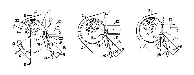
~ ike the known apparatus the apparatus according to the
invention shown in the drawing figures has a fixed jaw 2 and a
movable jaw 4, in each of which has been provided a
circumferentially arranged shallow tape guide channel,
indicated with the numerals 6 and 8, respectively (see Figs. 1
and 2~. There is a first welding electrode 12 that can be
moved to the space 10 enclosed by the jaws 2 and 4, and acting
in concert therewith there are specially formed counter
electrodes (13a', 13b'), the construction of which will be
elucidated below with reference to Figs. 3-7. In
contradistinction to the prior art these electrodes are
engaged in producing a seal not by supplying ultrasonic energy
;~ i 7~
7 AKU 2189
but by heating by microwaves and, equally in contradistinction
to the prior art, none of the electrodes is used to clamp the
sections of tape present between it as the tape is pulled back
to make a tight loop.
The bundle of cables around which the tape has to be
strapped in a tight loop is indicated with the numeral 22.
The jaws, opened to their maximum width (see Fig. la), are
placed around the bundle of ca~les Z2 and then closed. This
is the starting position. Subsequently, the cycle is started
by actuating the appropriate controls (the situation according
to Fig. lb) and the tape 24 is fed in the direction of the
arrow 26 by way of a suitable feeding mechanism.
As is illustrated in Fig. lb, the tape 24 passes through
the recess 11 in the pressure element 16, traverses the space
between the electrode 12 and the tips 13a', 13b' serving as
second electrode (see Fig. 7), its free end 27 (see Fig. la)
being placed in the channel 6 in upper jaw 2, having travelled
this channel, the tape is pushed through the channel 8 of the
lower jaw 4 and finally the free end 27, having traversed the
free space between the tips 13a, 13b and the surfaces 15a,
15b, is positioned in the space between the electrode 12 and
the tips 13a', 13b' (~ee also Figs. 3, 4, and 5). Since the
total length of circumference of the channels 6 and 8 is
known, the tape feeding mechanism may easily be so constructed
that, having been activated, it will feed the proper length of
tape and thus will stop when somewhat more than one complete
loop has been made. The tape is now clamped just b~neath the
free end 27 between the tips 13a, 13b of the clamps 14a, 14b
on the one hand and the surfaces 15a, 15b of the pressure
element 16 on the other (see Fig. 5). Next, the tape drive
mechanism is activated reciprocally by a suitable control,
causing the tape to be pulled back in the direction of the
arrow 28 ~see Figs. lc and ld).
Because the pressure element 16 can pivot about the shaft
9, the tip 15 of the pressure element 16 is moved somewhat at
a tilt in the direction of the arrow 17 (see Fig. lc) owing to
the pull exerted on the tape 24 when it is pulled back in the
2017~80
8 AXU 2189
direction of the arrow 28, as a result of which the tape 24 is
very greatly tightened between the tip sections 13a, 13b on
the one hand and the end surfaces 15a, 15b on the other (see
also Figs. 3, 4, and 5). For gripping enhancement the end
surfaces 15a, 15b may be provided with serrations and/or a
rough coating of, say, tungsten carbide chips. Because of
this movement of the end 15 and hence of the pressure surfaces
15a, 15b the tape is rigidly clamped, while the part of the
tape that is between the tip sections 13a~, 13b' on the one
hand and the end of the electrode 12 on the other still has
sufficient space for moving: consequently, the tape can be
tightened with a very high initial stress, so that, as is
illustrated in Fig. ld, a very ti~ht loop is formed around the
bundle of cables 22.
Next, also by means of a suitable drive and control the
electrode 12 is moved by means of a spring in the direction of
the tape 24 and bstween this electrode 12 and the tips 13a',
13b' there is created with a microwave generator a voltage of
such a magnitude and frequency (say, 2.45 GHz) over ~uch a
period of time as to effect the welding together of the tape
sections by microwave energy. The manner in which this is
effected according to the invenkion will be disclosed
hereinafter.
Fig. ld illustrates the situation in which the welding
has been completed. Then, with suitable switching, a cutting
wire 20 positioned underneath the electrode 12 is energized
(resistance heating) to melt off the tape very close (say, 0.2
mm) to the formed seal. The cutting wire 20 may take the form
of a thread- or band-shaped resistance element. In the latter
case the edge of the band may do the heat cutting. The
microwave welding is not attended with any thickening and
melting off directly below the seal prevents the formation of
a projection that might create problems later, during the
mounting of the bundle of cables. Finally, as is shown in
Fig. le, the jaws 2 and ~ are again separated by the jaw 4
being moved downward in the direction of the arrow 30, so that
they may be freed of the bundle of cables 22 now wrapped with
20174gO
g AKU 2189
the loop 24a, while the clamps 14a, 14b moving apart in the
direction of the arrows l9a, l9b (see Fig. 5) free the
apparatus of the now tightly strapped cable (see Fig. 5a).
The separate tape clamping means 13a, 13b, and 16 are
shown in greater detail in Figs. 3 through 5 and 5a. As the
tape 24 is pulled back to produce a tight loop, it is clamped
between the tips 13a and 13b, respectively, of the clamps 14a
and 14b, respectively, and a pressure element 16 that can be
tilted around the pivot 9. The clamps 14a and 14b and thus
th~ tips 13a and 13b can swing aside laterally around the
shaft 7 depicted schematically in Figs. 6 and 7. The
tightened, sealed tape is cut using an energized wire 20.
As is illustrated in particular in Figs. 3 through 5, the
pressure element 16 is constructed in a special manner; as was
stated earlier, it can pivot about the shaft 9 and has a
recess 11 for passing the tape indicated with the numeral 24.
At the front 15 of pressure element 16 there are, tapering in
an obtuse angle, the outer faces 15a, 15b, which act in
concert with correspondingly formed inner faces of the tips
13a, 13b on the clamps 14a, 14b (see Figs. 5 and 5a) for
clamping between them the tape indicated with the numeral ~4
just beneath the free end 27 o~ the tape. This tape is fed
via the recess 11, as will be elucidated further.
The various sections illustrated in the figures discussed
hereinbefore can also be seen in perspective in Figs. 6 and 7;
several of them will be discussed in greater detail with
reference to Figs. 12 and 13.
As is shown in Figs. 3-7, in the position in which the
clamps 14a, 14b are turned toward each other the tips 13a',
13b' forming the counter electrodes are a short distance
apart, so that the tape is not heated and sealed across its
entire width but a non-heated and hence unsealed section is
left in the middle. This situation may best be seen in Fig.
4. The latter shows the clamps 14a, 14b in the closed
position wherein the tape 24 is tightly gripped between the
tip sections 13a, 13b of the clamps 14a, 14b on the one hand
and the end surfaces 15a, 15b of the pressure element 16 on
2017~8~
AKU 2189
the other hand (see also Fig. 5). As will be further apparent
from Fig. 4 the counter electrodes 13a' and 13b' allow the
tape, while taking up a V form, to be pressed against the
cable bundle via the interspace formed between these counter
electrodes. This pressing is caused by the pulling force
acting upon the tape as it is being tightened.
As a result, the tape can be kept quite tightly strapped
during welding.
Clearly, welding the sections of tape together by using
microwave energy constitutes an important aspect of the
apparatus according to the invention and further detalls of
this are provided with referencs to Figs. 8a, 8b, 9a, 9b, and
10, 11, and 12.
Fig. 8a illustrates the use according to the invention
of a cylindrical, tapering microwave guide 32, which is in the
form of a cavity resonator with the cylindrical cavity 34 and
the tips 13a', 13b' of the clamps 14a, 14b. In the cavity 34
there is a cylindrical guide section 42 with a bore 44, into
which is guided the longitudinally slida~le central electrode
12. It is connected to the tip 12a projecting from wave guide
32 by means of a suitable drive mechanism indicated
schematically with a rectangle 46. With this drive mechanism
the electrode 12 can be reciprocated in the direction of the
arrows 48a, 48b in such a manner that a spring 14 presses
electrode 12 in the direction of the arrow 48a.
In the cavity 34 there is a tuning member 50 consisting
of a disc of dielectric material connected to an operating rod
52, which, in its turn, is connected to a suitable drive 54,
by means of which the rod 52 and hence the tuning member 50
can be reciprocated in the direction of the arrows 56a, 56b.
The microwave energy is supplied by a microwave generator
58, which provides a frequency of about 2.45 GHz and is
connected to the waveguide 32 via a coaxial cable 60, using a
suitable coupling element such as a coupling loop 62 connected
to its inner and its outer conductor.
In the depicted position of the tuning member 50 the
cavity resonator is not tuned to the frequency Fo of the
2017~
11 AKU 21~9
microwave signal supplied by the generator 58 and
consequently, as shown in Fig. 8b, the tension Vl between the
electrode 12 and the tips 13a', 13b' electric conductively
connected to the waveguide 32 and serving as counter electrode
will be too low to effect the production of a microwave
energy-welded seal. However, the tuning member 50 can be
moved to the right over the distance 1 to the position
indicated with dash lines, and during this movement the point
at which the cavity is in resonance is traversed, which is
attended with a great increase in voltage between the
electrode 12 and the tips 13a', 13b', viz. to above the level
Vmin required for producing a seal by microwave energy. on
continuing the movement to the right, the cavity resonator
goes out of resonance again, and the voltage is reduced.
As has been said, Fig. 8b is an illustration of the
voltage curve and it is clear that by having the movement take
place at an appropriate speed and, optionally, stopping in the
resonance point for a certai~ period of time, the period
during which the voltage between the electrode 12 and the tips
13a', 13bl is sufficiently high for welding may be long enough
to produce a satisfactory seal.
The embodiment illustrated in Figs. 8a and 8b has the
advantage that a microwave generator operatin~ at a fixed
frequency may be employed, but requires the presence of a
member to put the cavity resonator into and out of resonance.
Fig. ga refers to an embodiment in which the cavity resonator
is tuned to a fixed freguency and the tension between the
electrodes is controlled by varying the microwave generator's
frequency. In Fig. 9a the elements corresponding to the
embodiment according to Fig. 8a are indicated with the same
numerals with an added apostrophe~
The energy introduced into the cavity resonator 34',
which is nok equipped with a tuning member, is supplied by a
microwave generator 64, the frequency of which can be varied
with the schematically depicted control element 66 about a
central frequency Fo'/ which may e.y. be 2.45 ~Hz. In Fig. 9b
the frequency of the tension supplied by the generator 64 is
201~4~
12 AKU 2189
plotted on the abscissa and the tension V between the
electrode 12' and the tips 13a', 13b' on the ordinate, with
the minimum tension required to bring about satisfactory
sealing being indicated with the limiting value Vmin.
As is clear from Fig. 9b, the tension V will increase
greatly and exceed the Vmin value when varying the frequency
F' until it passes the resonance point of the cavity
resonator; by having the frequency variation take place
sufficiently slowly and, optionally, stopping temporarily, the
period during which the tension V exceeds the Vmin value will
be sufficiently long to ensure the production of a
satisfactory seal.
In a full frequency sweep the frequency may start at some
initial value below the resonance frequency Fo'l pass the
resonance frequency Fo' until it takes up a final value above
the resonance value Fo'~ then reduce so that it once again
passes the resonance value Fo' and finally return to its
initial value. Instead of one single full frequency sweep it
is possible to have two or more frequency sweeps per seal.
Depending on the particular circumstances it is also
conceivable that for each seal the frequency passes the
resonance point only once.
In the case of the microwave heating illustrated with
reference to Figs. 8a and 8b it must be seen to that, by
moving the tuning member 50, the cavity resonator 34 will be
in and near resonance for some time during each welding cycle.
The period in which this is the case must be of sufficient
length to enable the generation of the heat needed for a seal.
However, this period will constitute only a relatively small
portion of the total amount of time needed to carry out a
complete cycle of movement of the tuning member.
The effective time available for welding can be increased
by not having the movement of the tuning member 50 take place
in a "programmed" manner using a cam disc, but making it
dependent on the cavity resonator 32 resonating or not. When,
in that case, the tuning member 50 has reached a position in
which th~re is resonance and hence optimum generation of heat,
20174~
13 AKU 2189
it may continue in that position for some time. The advantage
of this arrangement lies in the fact that optimum generation
of heat can be maintained for a desired period of time instead
of its occurring only, as in the embodiment according to Fig.
8a, at the time when the tuning member 50 passes the position
in which the cavity resonates.
Such an arrangement may be effected by having the
movement of the tuning member 50 controlled by either
- the reflected signal from the cavity resonator, or
- the signal from a second coupling member provided in
the cavity resonator in addition to the first one
formed by the coupling loop 62.
Fig. 10 is a schematic view of how this arrangement can
be brought about when the movement of the tuning member is
controlled by a signal from the cavity xesonator 34. This
figure corresponds for the most part to Fig. 8a, so that the
same numerals refer to the same components. Included in the
feed line 60 is a directional coupling 135 known in itself,
via which part of the microwave energy reflected by the cavity
resonator 34 can be taken off. This part may be pic~ed off
via the connector 136.
Via the schematically indicated connection 137 the signal
is fed to the control device 54, which sees to maximizing the
microwave energy picked off (using power or phase relations)
by moving tuning member 50 by means o~ drive rod 52 into such
a position as to cause the cavity 34 to resonate.
Also shown schematicall~ in Fig. 10 i6 the alternative
arrangement: a second coupling member in the form of a rod
antenna 13~ is provided in the cavity resonator 34. Via
connector 139 and connecting line 140, optionally via
rectifier 141, the antenna signal is supplied to the control
device 54 via connection 142. Optionally, a rectifier may
also be incorporated into line 137.
As Fig. 11 shows, in analogue manner the microwave
generator 64 automatically may be so tuned as to bring cavity
34' into resonance. In a first embodiment there is
incorporated into the feed line 60' directional coupling 135
20~7~
14 AKU 2189
via which part of the microwave energy reflected by the cavity
resonator 34' is taken off to control the tuning of the
microwave generator 64. This control is indicated
schematically by connection 137 between the directional
coupling 135 and control member 66 of the microwave generator
64.
Also ~hown schematically in Fig. 11 is an alternative
manner of automatic frequency tuning: in the cavity resonator
34' there is provided a second coupling member 138 with which
a signal is taken off which is supplied to rectifier 141 via
connector 139 and connecting line 140. Via connection 142
rectifier 141 supplies the rectified signal to the control
member 66, which ~ees to the automatic tuning of microwave
generator 64. Connection 137 also may optionally include a
rectifier.
Especially suited to be used for such automatic frequency
tuning is a so-called solid state oscillator of, needless to
say, sufficiently reliable construction.
Fig. 12 shows a still further variant of the embodiment
according to Fig. 9a. In the embodiment of Fig. 12 a closed
loop is formed by the microwave generator 64, the coupling
loop 62', the cavity 34', the rod antenna 138, the connector
139 and the connecting line 140. Of this closed loop the
cavity 34' is the frequency determining element. Due to the
feedback of part of the microwave energy prssent in the cavity
34' to the microwave generator 64 by means of the antenna 138,
the connector 139 and the connecting line 140 the tension
supplied by the microwave generator 64 to the coupling loop
62' is automatically maximized (resonance condition).
The microwave generator may take the form of a magnetron,
or of a low power oscillator with planar triode amplifier, or
of a planar triode with the cavity (34') as the frequency
determining element, or of a low power oscillator with solid
state amplifier, or of a solid state amplifier with the cavity
(34'~ as the frequency determining element.
Although in the above-described constructions use is made
of a so-called coaxial cavity resonator with an inner and an
2~7 ~g3
AKU 2189
outer electrode (12 and 32, respectively), it is also
conceivable that a non-coaxial cavity resonator should be
employed. Such a non-coaxial cavity resonator is depicted
schematically in Fig. 13. In this figure the cavity resonator
is indicated with the numeral 144. This cavity resonator is
in the shape of a cylinder with a closed bottom face 145, a
cylindrical wall 146, and a stepped top face composed of the
semi-circular disc-shaped parts 147 and 148. Viewed in axial
direction of the cavity 144 said parts are spaced slightly
apart. The top part 148 has a tooth-shaped projection 149
which, viewed in axial direction, is positioned opposite to a
recess 150 in the bottom part 147. Microwave energy is fed to
the cavity reaonator 144 via the coaxial cable 151 and the
coupling loop 152 in analogous manner to that described for
the constructions according to Figs. 8 through 11. In the
cavity resonator an electric field is formed, indicated
schematically in Fig. 12 by the arrow E. This electric field
will continue upward up to the tooth-shaped projection 149,
which is comparable to the counter electrodes 13a' and 13b' in
the constructions accordin~ to Figs. 8 and 10 an~ 9 and 11, 12
respectively. By guiding the winding tape across the part
147, between the tooth-shaped projection 149 and the recess
150 situated opposite it, it may be sealed under the influence
of the heat generated as a result of the strong electric field
at the tooth-shaped projection 149.
The steps according to the invention may be carried out
in a hand-held apparatus provided with a pistol grip.
schematic view of such an apparatus, indicated in its entirety
with the numeral 70, is given in Fig. 14. It is composed of a
housing 72, to which the fixed jaw 2 and the moveable jaw 4
are attached as well as the pistol grip 78 incorporating a
bar-shapad electric motor 80. At the bottom the grip 78
supports the connector 82, which is connected to the tunable
connecting loop in the cavity resonator via a coaxial cable
(not shown) and by which feeding of the microwave energy takes
place, and the connector 84 for feeding the supply voltage to
the motor 80. The motor 80 is started by a trigger 86
2017~
16 AKU 2189
controlling a switch 88; through a suitable transmission 90
the motor operates a series of tape guiding rollers and
pulleys g2, around which the tape 102 has been guided in
zigzag fashion, and which are therefore capable of exerting a
strong pull on the tape. A second motor (not shown) operates
a series of cam discs 94 controlling tilting levers, ~uch as
the tilting lever 96, that program the various members to be
moved through follow-on rollers, such as the follow-on roller
98, and subsequently drive them. The operation of this second
motor and of motor 80 is coordinated by means of
microprocessor control (not shown).
There is a tape drum 100 from which the tape 102 is
unwound; as the figure makes clear, initially, on leaving the
drum 100, the tape 102 is perpendicular to the face of the
drawing, but in the guiding section 104 it i6 SO turned that
the portion 102a is in the plane of the drawing, in which
position it is guided around the rollers of the roller system
~2. On leaving the roller system the tape is turned back
through 90 again, so that the portion arriving at the jaws 2,
4 is again perpendicular to the plane of the drawlng.
According to a variant embodiment not shown in the drawings,
the drive system for the tape (including the tape guiding
rollers and pulleys) is turned through 90 with respect to the
situation a~ shown in Fig. 9, thereby ellminating the need to
turn the tape through 90 twice.
Fig. 15 gives a more detailed sectional view of the front
end 106 of the apparatus, with the movable jaw 4--which can
pivot about the shaft 7? (see Fig. 143--not having been drawn
for clarity: several of the members shown in Fig. 15 can also
be seen in Fig. 7. The figure is a view of the electrode 12
and its cylindrical guide 110 positioned within the cavity
resonator 112; the embodiment depicted operates in the manner
of the embodiment depicted schematically in Fig. 8a, although
it should be noted that the coupling loop for the supply of
the microwave energy has not been drawn in Fig. 15.
The electrode 12 is counter slidablP to the action of the
spring 114 and its tip 12a is connected to the coupling link
20~748~
17 AKU 2189
96 indicated in Fig. 14 and driven by the cam follower 98 and
one of the cams of the cam series 94. The cavity resonator
contains the tuning member 116 controlled through the pressure
rod 118 and also driven in a suitable manner from the cam
series 94 (Fig. 14).
Also shown in the figure are the melt-off wire 20 and the
pressure element 16 described hereinbefore which can pivot
about the shaft 9 and is provided with the passage 11 for the
tape: it is driven by the pressure rod 130 under the action of
the spring 128 to carry out a sliding movement as indicated by
arrow 136. The tape is fed via the tape guiding channel 132
and guided over the roller 134: the movement of the tape is as
has been described hereinbefore. Finally, one of the clamps is
indicated with the numeral 13a. Within the framework of the
invention many changes can be made.