Note: Descriptions are shown in the official language in which they were submitted.
1 ' ~~..'~ ~'
APPARA.Tt3S FOR INSTALLING FASTEPdERS
The invention relates to apparatus for installing
fasteners, and more particularly to such apparatus for
installing successively a plurality of fasteners by
repeated operation of a fastener installation tool which
is loaded with a plurality of fasteners forming a finite
supply of the fasteners to be installed thereby. The
invention relates particularly, although not exclusively,
to apparatus for the installation of fasteners of the
type known as blind tubular rivets
If the installation of fasteners is to continue after
the fasteners which were initially loaded into the tool
have been used; it is then necessary either to replace
the tool with another, loaded, tool, or to re-load the
original tool with a further supply of the fasteners to
be installed thereby.
There is a practical limit to the number of fasteners
which can be loaded into a tool, which limit depends upon
the size of the tool and the size of the fasteners: The
maximum size of tool is limited by the space available,
in use of the tool, for access to a workpiece. For
example, a tool which is used for the installation of
blind tubular rivets of the type widely available in many
P.337
-.
countries under the Registered Trademarks BRIV and
CHOBERT, can be loaded with a maximum of between 20 and
40 rivets, depending on the length of the rivet.
The tool must be reloaded when all the fasteners loaded
in it have been installed. Tn the case of a tool being
used, for example, on a production line where a certain
number of fasteners must be installed in each workpiece,
the tool must be reloaded when, having completed the
installation of the required number of fasteners in one
workpiece, the n~.unber of fasteners remaining in the tool
for subsequent installation is less than the number
required to be installed in the next workpiece. While
the tool is being reloaded it cannot be used to install
fasteners. If reloading requires that the tool be taken
apart and re-assembled, the downtime required for
reloading can be substantial, and may be as great as the
time during which the tool can be used to install
fasteners until it will need to be reloaded again, Thus,
~0 in the particular case of a repetition riveting tool
intended for installing blind tubular rivets of the pull
through type, in which a plurality of the tubular rivets
have to be loaded on to an elongate mandrel having an
enlarged head which is then pulled through each of the
~5 rivets successively in order to install the rivets in a
workpiece, the time required to reload the tool can be as
P.337
- 3 -
~.'~.~~s~ a
great as the time taken to install all the rivets tree
tool can hold.
The present invention is intended to reduce such down-
s time in the use of such tools.
Accordingly, the present invention provides, in one of
its aspects, apparatus for installing fasteners,
comprising a fastener installation tool for successively
installing a plurality of fasteners by repeated operation
of the tool, which tool has a fastener-carrying part
which may be loaded with a plurality of fasteners forming
a finite supply of the fasteners to be installed by the
tool, which apparatus includes reception means for
receiving the said fastener-carrying part from a used
tool, and presentation means for presenting to the~tool a
different fastener-carrying part loaded with a supply of
the fasteners.
The apparatus may include means for reloading such
installation tool with a further supply of the fasteners.
The apparatus may be arranged to exchange a loaded
fastener-cairying part of an installation -tool for a used
fastener-carrying part of a tool, and may be arranged to
re-load the used fastener-carrying part for subsequent
exchange with another used fastener-carrying part which
P.337
-
~~4~~~~
requires to be reloaded. Thus the installation tool may
be enabled to operate nearly continuously using
alternately reloaded fastener-carrying parts.
It may be that the apparatus includes reloading means for
reloading with further fasteners a used fastener-carrying
part of a tool. The reloading means may be operable to
reload a fastener-carrying part of a tool received by the
reception means, for subsequent presentation by the
presentation means.
It may be that the presentation means is arranged to
present successively a plurality of pre-loaded fastener-
carrying parts, and the reception means is arranged to
receive those fastener carrying parts successively after
each has been used.
The reception means and its associated presentation means
may be at separate stations.
Preferably the reception means and the presentation means
are provided at the same station.
Preferably the apparatus includes; reception means far
receiving a used fastener carrying part from a tool;
presentation means for presenting. to the tool a re-loaded
P.337
- 5 -
%~'':'~'
fastener-carrying part which has previously been received
by the reception means and re-loaded with fasteners; and
alternative presentation means for alternatively
presenting to the tool a different preloaded fastener
s carrying part.
The apparatus may include a plurality of alternative
presentation means.
The apparatus may include second reception means for
alternatively receiving a used fastener-carrying part.
The fastener installation apparatus may include control
means for controlling the operation of the apparatus.
The control means may be programmable. The control means
may be programmed to actuate release of a used fastener-
carrying part to the reception means when the number of
fasteners remaining in the tool and available for
subsequent installation by the tool falls below a
predetermined minimum number.
The fastener installation apparatus may include means for
moving the tool to a desired position. The control means
may be operable to control the moving means to move the
'?5 tool to the reception means and to cause release of the
fastener-carrying paxt to the reception means when the
P.337
-s-
number of the fasteners remaining in the tool and
available for subsequent installation by the tool falls
below a predetermined number.
When the fastener installation apparatus includes
reloading means, the control means may also operate to
control the reloading means to reload the used fastener-
carrying part received by 'the reception means.
In a preferred embodiment of the invention, the fastener
installation apparatus is arranged to install blind pull-
through tubular rivets.
An embodiment of the invention will now be described, by
way of example, with reference to the accompanying
drawings, in which:
Figure 1 is a simplified perspective view of an automated
workstation incorporating fastener installation apparatus
according to the invention, showing the principal parts
of the apparatus, and their organisation;
Figure 2 is a sectional elevation of a fastener
installation tool forming part of the apparatus of Figure
1;
p.337
.7
a'$~'_~.'s~~~
Figure 3 is a scrap perspective view of a nest far the
reception and/or presentation of part of an installation
tool;
Figure 4 is a sectional elevation on the line IV-IV of
Figure 3;
Figure 5 is a side elevation of part of a rivet feeding
and loading means forming part of the apparatus of Figure
1;
k'igure ~ is a plan view of part of the rivet feeding and
loading means;
Figures 7 to 13 are schematic elevational views showing
the positions of principal parts of the apparatus in
successive stages of operation.
Referring first to Figure 1, the automated workstation
illustrated by way of example includes a workpiece
conveyer 10 and a power-operated robot arm 12 with which
is associated fastener installation apparatus embodying
the invention. Workpieces 14 comprising members to be
fastened together are conveyed by the conveyer to the
workstation where the members are fastened together, and,
after being fastened, are then conveyed away from the
P.337
-a-
~r'~:'"~:~~°
workstation.
At the workstation, the workpiece members are fastened
together by installing one or more fasteners in
registering apertures in the workpieces.
The installation of the fasteners is performed by a
power-operated fastener installation tool 1~ which is
mounted on and carried by the robot arm 12 whereby the
tool 16 can be moved and manipulated as necessary, and
particularly so as to install fasteners in a succession
of the workpieces 14 being conveyed through the
workstation.
The installation tool 16 of this embodiment, shown in
greater detail in Figure 2, is a repetition riveting tool
constructed for the installation of tubular blind rivets,
and is of generally conventional construction, although
it incorporates some features by which it is adapted to
facilitate operation in a manner to be described.
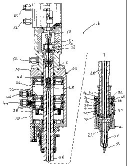
The tool 16 comprises essentially an annular abutment 1~,
provided in this embodiment by a pair of cooperating
separable nose jaws 20 forming part of a nose assembly
21, for supporting a rivet in a rivet setting operation,
and an elongate headed mandrel 22.on to which a plurality
P.337
_ g _
~~~,'~~~p;
of blind rivets forming a finite supply of the fasteners
to be installed are loaded prior to use of the tool,
together with means for advancing the rivets along the
mandrel so as to pass the abutment one at a time and lie
between the abutment and the head of the mandrel, and
means far repeatedly reciprocating the mandrel lengthwise
of its axis relative to 'the abutment so as to pull the
head of the mandrel through the bores of each of a
succession of the rivets supported in turn by the
abutment, whereby the rivets can be deformed and set in a
well known manner.
The tool 16 is designed for pneumatic operation, and is
constructed as a unit which is detachably mounted on the
robot arm 12 by means of a tool exchanger interface 24.
The tool exchanger interface 24 has two complementary
parts through which, in this embodiment, the tool is
supplied with compressed air, and the necessary
connections for electrical sensors are made, and permits
another tool of the same type, or of another type if
desired, to be substituted for the tool 16, in a well
known manner.
Although the tool 16 will operate in, and can be
manipulated into any attitude or orientation by the robot
arm 12, in the following description it is assumed, for
P.337
- lU -
a~~~.~~~
ease of understanding, that the tool is orientated so
that the longitudinal axis of the mandrel 22 is vertical,
with the head of the mandrel lowermost and the abutment
Z8 facing downwardly.
Referring more specifically to Figure 2 of the drawings,
the tool 16 comprises, in addition to the nose assembly
21 and the mandrel 22, a pneumatic actuator 26 which
provides the means for producing the relative
reciprocation between the abutment 18 and the mandrel 22,
and the means for advancing rivets along the mandrel.
The actuatar comprises primarily an elongate tubular
barrel 28, and a housing 30 which contains other parts of
the actuator. The housing 30 contains two principal
functional units, namely mandrel gripping means for
releasably gripping the upper end of the mandrel 22, and
pulling means whereby the housing 30 can be caused to
reciprocate relative to the barrel 28 in the direction
lengthwise of the axis of the barrel.
The housing 30 is located generally around the upper end
of the barrel 28, and the nose assembly 21 (which is not
part of the actuator) is secured in readily detachable
manner to the lower end of the barrel at a distance from
the housing 30 which will influence the maximum number of
P.337
w 11 -
~~.,'~~ ~,
fasteners with which the tool can be loaded, as will
became apparent.
The barrel itself is secured to the tool exchanger
interface 24 and is thereby held in fixed positional
relationship to the robot arm 12 while the housing 30 is
movable relative to the barrel and the robot arm. The
barrel 28 is, in effect, the piston rod of a pneumatic
piston assembly which is reciprocable in two in-line
pneumatic cylinders defined within the housing 30.
The mandrel gripping means is contained i.n the upper part
of the housing 30, and comprises a pair of tapered
gripping jaws 52 carried by a generally tubular jaw
carrier 54, and a jaw-closer 56 in the form of an annular
bush seated within the housing so as to resist downward
movement under pressure, and having a downwardly tapering
bore. A double acting pneumatic jaw-closing piston 58
reciprocable in a cylinder (not shown) is operable by
compressed air supplied through a clamping port 60 to
drive the jaw carrier 54 downwardly, thus forcing the
j aws 52 into the bore of the j aw closer 56 and causing
the jaws to close and grip the upper end of a mandrel
inserted between the jaws in the jaw carrier.
Conversely, air supplied through a release port 62 raises
the piston 58, allowing the jaws . to relax 'their grip on
P.337
- 12 _
~~ ~.."~~ ~'m
the mandrel so that the mandrel can be withdrawn from the
actuator.
The pulling means is contained in the lower part of the
housing 30, below the gripping means. Thus, the lower
part of the housing comprises a pulling section 32 having
a bore of large diameter and of which the length is
divided equally by annular wall 34 into coaxial upper and
lower cylinders 36, 38 respectively. The annular wall 34
is keyed and sealed to the internal wall of the pulling
section 32.
Disposed, and slidable, within the upper and lower
cylinders 36, 38 are pistons 40, 42 respectively. The
pistons 40, 42 are both keyed to the barrel at positions
spaced from the upper end of the barrel 22, and divide
their respective cylinders into upper and lower chambers.
Compressed air can be admitted to the two upper chambers
through separate ports, of which only the port 44 is
shown in Figure 2, to move the pistons 40, 42 and the
barrel relative to the housing 30 to produce a pulling
stroke. Admission of air through a return port 46 inta
the lower chamber of the upper cylinder 30 effects a
return stroke by producing relative movement of the
pistons and barrel in the opposite direction. As the
h.337
- 13 -
~~'.~~a ~:~
position of 'the barrel 28, and hence of the abutment 18,
is fixed relative to the robot arm 12, the pulling and
return strokes are manifest as actual movement of the
housing 30 relative to the robot arm 12, and the abutment
s 18.
As previously indicated, in the normal condition of the
tool, that is to say when the tool is ready to install a
fastener, the upper end of the mandrel 22 is clamped
between the gripping jaws, and the mandrel extends
axially through the barrel 28 and through the nose
assembly 21 which is attached to the lower end of the
barrel. The enlarged head of the mandrel 22 is normally
disposed below the abutment 18, as shown in Figure 2 in
which the tool is shown at the end the return stroke with
the pistons 40, 42 at the upper ends of their respective
cylinders. A plurality of tubular rivets to be installed
are disposed an the mandrel, one of the rivets having
descended through the nose assembly 21 to lie between the
abutment 18 and the head of the mandrel and the other
rivets on the mandrel are positioned above the nose jaws
20.
Actuation of the tool, by supplying compressed air to the
upper chambers of the cylinders 36, 38, causes the
housing 30 to move upwardly, pulling the mandrel upwardly
1'.337
1a _
'r~~~~.'~La~:
so that the mandrel head is drawn through the bore of the
rivet which is below and supported by the abutment.
A cursor 48, in the form of an annular piston freely
slidable within the bore of the barrel and surrounding
the mandrel, is driven by compressed air entering the
tool at a cursor drive port 50 and passing downwardly
through the upper end of the barrel, to urge 'the rivets
downwardly along the mandrel so that, as each lower most
rivet is installed, another is forced past the nose jaws
into the position previously occupied by the now
installed rivet.
The nose assembly 21 is attached to the lower end of the
barrel by engagement with a complementary sleeve 64 which
surrounds the lower end portion of the barrel 28. The
sleeve 64 is threadedly engaged with the barrel on which
it can be more or less permanently retained. The sleeve
has four recesses 66 of part-spherical shape disposed
equi-angularly around its circumference and into which
six steel balls 68 carried by the nose assembly can
engage so as to retain the nose assembly on the sleeved
lawer end of the barrel 28.
Thus, the nose assembly 21 comprises a tubular body 70
having an axial bore 72 into which 'the sleeved lower end
P.337
- 15 -
of the barrel can be inserted, and six radial bores in
which the six balls 68 are housed. A shroud 74 surrounds
the body 70 and is movable to cause either the release or
the locking engagement of the nose assembly relative to
the sleeved end of the barrel. The shroud 74 has a
flared upper Bart 76 and a cylindrical lower part 78.
The lower part 78 surrounds the body with some clearance,
forming an annular housing far a helical compression
spring 80, The spring 80 abuts a flange of the body at
its lower end, and its upper end engages a shoulder of
the shroud, so that the spring is compressed and
resiliently urges the shroud upwardly into engagement
with a stop 82.
The upper part 76 of the shroud flares, both externally
and internally, in the direction away from the lower part
so that the lower part 78 presents an external annular
shoulder 84 at the point where it meets the smaller
diameter end of the upper part 76. Internally, the
flared upper part reduces towards the lower part to form
a collar region 86 which is a close sliding fit around
the body 70. In the spring biased upward position of the
shroud, the collar region 86 thereof urges the steel
balls 68 inwardly so that they partly emter the recesses
66 of the sleeve 64 and thus secure the nose assembly to
the sleeved end of the barrel. .However, on urging the
P.337
,. t~
._ 16 _ r~m.~~~~:
shroud downwardly against the spring, the collar region
is moved out of register with the balls 68, and the
internally flared region of the upper part comes into
register with the balls, allowing them to move radially
outwardly into the conical space defined between the
flared part of the shroud and the body 70 at least
sufficiently for the balls to disengage from the recesses
66 in the sleeve 64. Thus, on urging the shroud
downwardly, the nose assembly is unlocked and can be
separated from the sleeved barrel.
The tool 12 just described can be loaded with up to 40
fasteners of a given size, and when by use of the tool
they have all been installed or there remains an
insufficient number to complete another task, it is
necessary to reload the tool with further fasteners. The
operation of the tool and the number of fasteners
installed by the tool is monitored by suitably programmed
control means, of which some mention will be made
subsequently. The control means also initiates and
controls a programme of events whereby a tool having a
depleted supply of fasteners is reloaded.
Reloading is effected by removing the nose assembly 21
together with the mandrel 22 and any remaining fasteners
from the actuator 26, and then either reloading the
P.337
_.
~U~..'~~~ x~
mandrel and replacing it together with the same nose
assembly into the tool, or substituting another loaded
mandrel, together with another nose assembly, for that
removed. The latter course is more expedient since it
avoids delaying use of the tool while further fasteners
are loaded on the mandrel, and hence reduces the
necessary downtime.
It is to be understood that, in order to reload a mandrel
22 it is necessary to release it from the gripping jaws
52 and remove it from the actuator sa that further
fasteners carx be threaded on to the mandrel at the end
remote from the mandrel head. It is not necessary,
however, to separate the mandrel from the nose assembly,
for reloading, because the column of rivets with which
the mandrel is loaded must be above the nose assembly,
and is advanced downwardly as required by the cursor 48.
The mandrel, of course, constitutes the fastener-~aarrying
part previously referred to.
Thus, the mandrel and the nose assembly of a tool can
remain more or less permanently associated through
several cycles of use and reloading. In view of this,
the more general term "nose equipment" is used
hereinafter to refer to the combination of a mandrel and '
P.337
._ 13 _ ~~:~1,~~~
its associated nose assembly.
Means will now be described whereby, under the control of
the control means, the tool can be reloaded by removal of
the nose assembly and mandrel from the tool and
substitution of another nose assembly and a loaded
mandrel, and whereby, furthermore, the mandrel so removed
can be reloaded so as to be ready together with the
removed nose assembly, to replace the previously
~.0 substituted mandrel and nose assembly when the tool next
requires reloading.
Thus, by using a single actuator tagether with two sets
of nose equipment which are each used alternately .i.n
rotation while the other is being reloaded, the downtime
required for the tool is anly that taken to substitute
one set of nose equipment for another.
Referring again to Figure 1, the automated workstation
illustrated has two independent systems for enabling the
.reloading of a tool, one of which is relatively
unsophisticated, and regarded as an alternative to a
preferred system, and will be described first and
briefly, and the other of which is more sophisticated and
preferred and will be described subsequent. Either of
the systems can be provided or omitted, or as in 'this
P.337
embodiment, both can be provided for use as alternatives.
The first system is represented by the provision of
nests, of which, in this embodiment, there are three,
indicated by the references 90, 91, 92. The nests 90,
91, 92 are mounted on a rack 94 so as to be within reach
of the robot arm 12. each nest provides a receptacle for
receiving and holding a set of nose equipment, and
includes means for releasing the nose assembly from an
actuator so that, after also releasing the mandrel from
the gripping jaws, the actuator can be moved away leaving
the nose equipment in the nest.
Of the three nests 90, 91, 92, at least one is normally
left vacawt and ready to receive a set of nose equipment,
and at least one other normally contains another , set of
nose equipment having a loaded mandrel, which may have
been loaded in any suitable manner, ready for
presentation to a actuator from which the nose equipment .
has been removed.
Tn addition to the nests, the rack may also hold a spare
complete tool, loaded with fasteners, and ready to be
substituted for 'that attached to the robot arm l2 through
the tool exchange interface 24 whenever the need arises.
P.337
- 20 -
A nest 96a, identical with the nest 90, is shown in
Figure 3 in perspective and in somewhat greater detail
than in Figure 1, and is shown in Figure 4, in cross
section on the lines IV-IV of Figures 1 and 3 together
with a nose assembly and a partly loaded mandrel disposed
in the nest.
Referring to Figures 3 and 4, the nest 96a comprises a
hollow receptacle 98, defining a cavity, the shape of
which is generally complementary to that of the nose
assembly 21 of the tool 12, which is to say that the
cavity has a lower region 100 which fits closely around
the nose jaws 20, and an upper region 102, of larger
diameter than the lower region, in which the upper part
of the nose assembly, including the shroud 74, can be
accommodated with slight radial clearance. Between the
upper and lower regions of the cavity the receptacle
defines an annular shoulder 104 on which the body 70 of
the nase assembly can rest while the nose jaws 20 extend
downwardly into the lower region 100 of the cavity. A
tubular blind rivet 106 is located on the mandrel 22
between the abutment 18 and the head of the mandrel, and
the lower end of the cavity is closed by an stop. screw .
108 which is threadedly engaged with the receptacle 98.
The stop screw 108 is adjustable in height within the
lower region 100 of the cavity so as to support the
P.337
-\
- 21 --
a ~~~.~:~
mandrel 22 while allowing minimal clearance for the rivet
106 between the abutment 18 and the mandrel head.
The receptacle 98 is mounted on a table 110 through which
the lower part of the receptacle extends. The table 110
also supports a pair of pneumatic retractors 112, 113
which form part of the nest 96a and are disposed on
diametrically opposite sides of the receptacle. Each
retractor comprises a pneumatic retractor cylinder 114
disposed below the table and having a retractor piston
116 vertically reciprocable therein. The piston 116
extends upwardly through the table, and supports a pawl
118 which is pivotally mounted in a trunnion 120 which in
turn is adjustably mounted on the upper end of the piston
116. The pawl 118 comprises a substantially vertical
limb 122 the lower end of which pivots in the trunnion
120, and a claw 124, the claws of the two retractors
extending towards each other and radially inwardly of the
receptacle. The upper part of the receptacle is
externally flared, forming an external cam surface 126
for the pawls, and has two diametrically opposed radial
slots 127, 128, in which the claws 124 are movable in
directions both vertical3y and radially of the
receptacle. Each of the pawls has a pair of rollers 130,
131 journalled for rotation about a horizontal axis
passing through the pawl at the .angle between the claw
P.337
22 ~.'~~~~~',
and the vertical limb, the rollers being arranged to bear
and roll on the flared external cam surface 126 at the
upper end of the receptacle on each side of the slot in
which the claw is disposed. Each pawl is biased, by a
spring-loaded plunger 133 mounted in the trunnion, to
pivot so that the claw tends to move radially inwardly of
the receptacle, but is limited in the extent of its
inward movement by the engagement of the rollers against
the cam surface of the receptacle.
The retractor cylinders 114 are supplied with compressed
air under the control of the control means.
The operation of the nests is as follows.
1S
When the control means senses that the tool 16 requires
to be reloaded, the robot arm carries the tool to a
position directly above the nest 90 and then lowers the
tool so that the nose assembly 21 enters the cavity of
the receptacle 98 and the lower end of the body 70 rests
on the shoulder 104. This is the condition shown in the
right-hand half of Figure 4.
The control means then operates to admit air through the
release port 62 of the ac~.uator, causing the piston 58 to
retract so that the gripping.jaws r~Z.ax their grip on the
F.337
- 23 -
~1."~~~~'-j
tail end of the mandrel, and at the same time operates to
admit air to the upper chambers of the two retractor
cylinders 114 of the nest 90, causing the retractor
pistons 116 to be pulled downwardly relative to the
receptacle 98. Descent of the pistons 116 causes the
spring biassed pawls 118 to descend also, and, as the
rollers 130, 131 are able to follow the cam surface 126
of the receptacle, the spring biassed pawls pivot so that
the claws move radially inwardly and engage the annular
shoulder 84 on the shroud of the nose assembly.
Continued descent of the pistons 116 causes the pawls to
pull the shroud downwardly, thus releasing the nose
assembly from engagement with the barrel of the actuator.
With the mandrel and nose assembly ( that is to say, the
nose equipment) thus released from the actuator and held
in the nest, the actuator of the tool is then~raised
vertically by the robot arm until it is clear of the
upper end of the mandrel, leaving the nose equipment in
the nest. The robot arm then traverses to position the
actuator above another nest which holds a set of nose
equipment having a suitable load of fasteners, such as
the nest 91, and then lowers the actuator so that the
sleeved end of the barrel decends around the loaded
mandrel and enters into the nose assembly in the nest 91.
The retractor pistons of the nest 91 are then urged
upwardly by air admitted to the lower chamber of the
P.337
_ 7 4 _.
e~~.~..~A ~ ~~
retractor cylinders, raising the pawls arid thus allowing
the shroud to rise under the influence of the helical
spring 80. As the shroud rises, the steel balls are
urged radially inwardly into engagement with the sleeve
end of the barrel, thus locking the nose assembly to the
actuator. Simultaneously with the rise of the retractor
pistons, air is admitted through the clamping port 60 to
urge the piston 58 and the jaw carrier 54 downwardly,
thus clamping the loaded mandrel between the gripping
ZO jaws 52.
As the pawls rise, their rollers follow 'the flaring cam
surface of the receptacle and the pawls are thereby
caused to pivot, moving the claws radially outwardly and
thus disengaging the claws From the nose assembly.
Thus the nose assembly and the actuator are reassembled
and released from the nest 92, and the tool is ready to
be moved away from 'the nest by the robot arm and to
resume installing fasteners.
The first alternative system just described does not
include any provision for reloading a mandrel with
further fasteners. However, the nest 96a is part of the
preferred second system, previously referred to, which
includes means for reloading a mandrel.
P.337
- 25 -
~~~.'~a~E:~,~;
The second system is illustrated schematically in Figures
7 to 13 which also illustrate successive stages in the
operation of the system.
Thus referring to Figure 7, the table 110 previously
referred to is an indexing table mounted for indexing
rotation through 180° about a vertical axis on a suitable
support 140 within reach of the robot arm 12.
A pneumatically operated rack and pinion indexing
mechanism 142, of conventional and commercially available
type, is mounted on the support 140 and supports and
produces' the indexing movement of the table 110 in
response to the supply of pressurised air under the
control of the means in a well known manner.
The table 140 supports the nest 96a and a second nest 96b
identical to the nest 96a.
The nests 96a and 96b are disposed equidistant from and
on diametrically opposite sides of the rotational axis of
the indexing table so that, on indexing the table through
180°, each nest moves into the precise position in space
previously occupied by the other.
F.337
-1
..
The position occupied by the nest 96b, as seen in Figure
1, is a station for the reception and the presentation of
nose equipment from and to an actuator 26 carried by the
robot arm 12, and the position occupied by the nest 96a
as seen in Figure 1, is a reloading station at which a
mandrel of the nose equipment held in the nest 96a can be
loaded or reloaded with fasteners. Tndexing the table
through 180° moves both the nests 96a and 96b from their
respective stations to the other of the stations.
The mandrels of the riveting tools are made of steel wire
and are easily flexible. Tt is therefore necessary to
provide means for accurately locating in transverse
position the upper ends of mandrels of nose equipment
held in the nests 96a and 96b in order to facilitate both
the loading or reloading of such mandrels with further
rivets, and also to facilitate the reassembly of an
actuator 26 carried by the robot arm 12 with nose
equipment held in one of the nests.
Accordingly, the indexing table 110 carries means for
locating the upper end portion of a mandrel held in each
of the nests 96a and 96b.
The locating means comprises a column 144 mounted
vertically at the rotational axis of the table, and two
P.337
27 -
;y b
pneumatically operable mandrel locators 146a and 146b
supported by the column at a height above the nests 96a
and 96b respectively, which will be near to, but not at,
the upper ends of mandrels of nose equipment held by the
nests.
Each mandrel locator comprises a double acting pneumatic
actuator and a pair of locating jaws which can be
operated by the locator actuator so as to move between a
mandrel-holding position in which the jaws are positioned
vertically above the respective nest and axe closed about
a mandrel of nose equipment held by the nest, and a
position in which the jaws are opened, and the mandrel
released, and are retracted away from the position
vertically above the nest.
Thus, in the mandrel-holding position, the locating jaws
engage the mandrel at a position spaced a short distance
from its upper end and locate it precisely so that either
a tubular rivet or an actuator of a riveting tool can be
threaded on to the upper end of the mandrel. More
particularly, the locating jaws are shaped so that the
upper; end of a mandrel which is flexing, or slightly bent
out of line, may be gathered into a precisely fixed
transverse position relative to the nest holding the
mandrel.
. . P.337
_ 2g _
Also mounted on the support 140, in a position adjacent
to the indexing table 110, is means for loading tubular
rivets on to a mandrel disposed in one of the nests,
which, in the phase of operation shown in Figures 1 and
7, is the nest 96a.
The loading means of this embodiment comprises a bowl
feeder 150 of conventional construction and arranged to
orientate and feed rivets along a flight 152.
The tubular rivets illustrated in the drawings are of the
type sold under the Registered Trade Mark "BR1V", and
comprise a shank of generally cylindrical and elongate
shape, and a radially enlarged head at one end of the
shank with a bore passing axially through the shank and
head. The orientated rivets pass along the flight with
their heads uppermost and supported by the flight and
with their shanks depending below the flight through a
slot in the flight.
The end of the flight .remote from the bowl feeder is
provided with a spring loaded gate 154 whereby 'the rivets
are prevented from freely leaving the end of the flight,
as shown in Figure 6. Rivets arriving at the gate 154
are periodically removed from. the flight and are
P.337
_ 2g _
transferred by a rivet transfer device 160 to a mandrel
disposed in that one of the nests 96a and 96b which, in a
given phase of operation of the apparatus, is at the
loading station.
The rivet transfer device 160 is shown more particularly
in Figure 5, and comprises a pneumatic jack 162 having a
cylinder housing mounted on the suppart 140, and three
vertically reciprocable pistons 164. Mounted on the
upper ends of the pistons 164 is a transfer gripper 166.
The transfer gripper 166 comprises a pneumatic cylinder
housing secured to the upper ends of the pistons 164, and
three horizontally reciprocable pistons 168 to which is
attached a rivet carrier 170. The rivet carrier 170
includes a pair of horizontally opposed power--operated
rivet gripping jaws 172 arranged to engage and grip a
rivet held at the spring-loaded gate 154 of the flight,
and, on suitable movement of the horizontally
reciprocable pistons 168, to pluck the rivet from the
f light, through the gate, and move the rivet to a
position precisely above the upper end of a mandrel
disposed in the nest at the loading station. On causing
the vertical pistons 164 to descend, the jaws 172 holding
the rivet are lowered so that the rivet is threaded on to
the upper end of the mandrel. The jaws 172 then release
P.337
- 3U -
2a
the rivet which is able to descend by gravity, past the
mandrel locators which open momentarily to allow the
rivet to pass, and join any rivets previously disposed on
the mandrel, forming a column of rivets.
As soon as the jaws 172 have released the rivet on the
mandrel, the horizontally reciprocable pistons 168 are
retracted and the transfer gripper is raised by the
vertically reciprocable pistons 164 to the position in
which the gripper is ready to remove the next rivet
waiting at the gate 154 of the flight.
The sequence of events just described is performed
rapidly under the control of the control means, and
enables a mandrel disposed in the nest at the loading
station to be Loaded with a plurality of rivets,,fed one
at a time.
Some successive phases of the operation of the rivet
transfer device are shown in Figures 7 to 13.
Referring now specifically to Figures 7 to 13 of 'the
drawings, and initially to Figure 7, the operation of the
apparatus to reload a used tool, using the preferred
reloading system, will now be described.
P.337
w
- :~ 1 -
~~.'~R~'~Aa
Figure 7 shows workpieces 14 on the conveyor 10, the
robot arm 12 which supports an installation foal 16 which
has installed part of its load of tubular rivets in a
workpiece on the conveyor and requires to be reloaded
with rivets, and the reloading means adjacent to the
conveyor.
The nest 96b is positioned at 'the reception and
presentation station by the indexing table 110, and is
vacant, and the nest 96a is positioned at the reloading
station and holds a set of nose equipment, including a
mandrel 22a, which is additional to the set of nose
equipment forming part of the tool 16 held by the robot
arm.
As shown in Figure 7, the mandrel 22a has been fully
loaded with a column of the tubular rivets which extends
up the mandrel to the mandrel locator 146a, and is ready
to replace the mandrel of the tool 16 in which the load
of rivets is depleted.
The robot arm then moves the tool 12 into position
vertically spaced above the vacant nest 96b as shown in
k''igure 8: the locating jaws of the mandrel locator 146b
are open.
P.337
~~:~'~~~~:i2
The robot arm then lowers the tool between the open
locating jaws until the nose equipment of the tool enters
the receptacle of the nest 96b as shown in Figure 9. The
mandrel of the tool 12 is then released from the grip of
the gripping jaws 52 by operation of the jaw closing
piston 58, and the pneumatic retractors of the nest 96b
are operated to pull their pawls downwardly, thus
releasing the nose equipment from the actuator of the
tool 16.
to
The robot arm then rises, carrying the actuator 26 of the
tool 16 upwardly, and leaving the nase equipment of the
tool in the nest 96b as shown in Figure 10. The actuator
26 rises clear of the mandrel 22, arid the locating jaws
then close around the mandrel.
The indexing table 110 then indexes through 180°,
transposing the nests 96a and 96b so that the nose
equipment just received from the tool 12 is moved to the
loading station, and the nose equipment with the ready
loaded mandrel 22a is moved to the receptian and
presentation station below the actuator 26, as shown in
Figure 11.
The robot arm then lowers the actuator 26 so that the
mandrel 22a passes into the .bar,rel, threading its way
P.337
- 33 -
~~~.~r~~
through the cursor 48, and eventually into position
between the gripping jaws 52. As the actuator descends
and the lower end of the barrel approaches the mandrel
locator 146a, the locating jaws open to allow the barrel
to pass.
When the sleeved lower end of the barrel has fully
entered the nose assembly 21 in the receptacle of nest
96a, the jaw closing piston 58 is operated to close the
gripping jaws 52 of the actuator on the mandrel 22a, and
the actuator pistans of the nest 96a are operated to
raise the pawls so that, guided by the cam surface of the
receptacle, the pawls allow the shroud to rise and urge
the balls of the nose assembly into engagement with~the
sleeved end of the barrel, thus locking the loaded nose
equipment to the actuator 26, and releasing their,hold on
the nose assembly.
Meanwhile, the nose equipment earlier removed from the
tool 12, and now in the nest 96b at the reloading station
is being reloaded with further rivets by the reloading
means, as previously explained. This stage is shown in
Figure 12.
The tool 12, now reassembled using the loaded nose
equipment including tie mandrel 22a,.is free to be moved
P.337
. \
- 34 -
~~9~.''7a~
away from the reception and presentation station by the
robot arm, and to resume installing rivets in workpieces
on the conveyor .
Reloading of the nose equipment in the nest 96b continues
until the mandrel 22 thereof is fully loaded, and then
stops, and the thus reloaded nose equipment remains at
the reloading station until required to replace the nose
equipment of the tool 12 when the tool next needs to be
reloaded.
Reference has been made to the control means by which the
operation of the apparatus is controlled, and this will
now be described.
1.5
The control means is of a generally conventional type,
and uses conventional parts in a manner which is
generally well understood in the control of apparatus for
performing operations. The following description is,
therefore, only concerned with the principal parts and
their organisation to effect the necessary contral over
the operation of the apparatus for installing fasteners.
It will be appreciated that a principal feature of the
.automated workstation shown in figure l is the robot arm
12, and that the robot arm is provided with a general
35 ~~~..'d~a~i q
cantroller which is housed in the mounting far the robot
arm. The general controller is programmable to control
not anly the operation of the robot arm 12, but also the
operation of any other ancillary apparatus associated
with the robot arm at the workstation. The general
controller converses with individual controllers of
ancillary apparatus at the workstation, so that the
operation of all parts of the workstation are
coordinated.
The operation of the installation tool 12 and the
reloading means, and the logical co-ordination of their
operations are under the control of a programmable logic
controller.
The logic controller receives data input from sensors of
various types which are disposed at appropriate locations
to sense events occurring in the apparatus; it converses
with the general controller, and it gives outputs which
directly or indirectly actuate the performance of the
various operations which parts of the apparatus have to
perform.
Thus, a number of sensors are disposed at appropriate
positions to monitor various conditions and the operation
of the various actuators of the apparatus. The sensors
P.337
.\
- 3 6 - ec~.~~
include optical sensors, inductive proximity sensors, and
magnetic reed switches, and are deployed to monitor the
operation of the riveting tool 12 and the reloading
means, and pass resultant data to the programmable logic
contraller. Particular mention is made here of the use
of sensors to monitor the presence or absence of rivets
at the gate 154 of the flight, the opening and closing of
the rivet gripping jaws and the presence or absence of a
rivet between them, the end points of reciprocation of
14 the transfer gripper in both vertical and horizontal
directions, the opening and closing of the mandrel
locators 146a and 146b, the presence or absence of nose
equipment in the nests, and the reciprocatory movements
of the retractor pistons 116, the indexing movements of
the indexing table 110, and to sense when a column of
rivets on a mandrel being reloaded at the loading station
reaches a predetermined height. Sensors are also employed
to monitor the movements of the jaw-closing piston 58,
and the reciprocatory movements of the barrel 28 relative
to the housing 30 of the actuator.
Outputs from the logic controller operate solenoid-
operated valves which control the flow of pressurised air
in the pneumatic circuits from a source of compressed air
to the actuator 26 and the pneumatic cylinders of the
reloading means:
P.337
- 37 -
~'~~.~~ ~'~
The programmable logic controller includes means for
keeping count of the numbers of rivets in the system and
available for installation. Thus, the number of rivets
loaded on to mandrels at the reloading station and
subsequently loaded into the installation tool 12 is
known from the size of the rivets and the predetermined
height of the column of rivets loaded on to the mandrel,
and the number of rivets installed by the tool is counted
by the logic controller. A comparator in the logic
controller is then able to calculate the number of rivets
remaining in the tool and available .for installation in
workpieces. When the number of rivets in the tool falls
below that predetermined number of rivets needed to
perform a complete task, the control means allows
completion of the task in hand, and then initiates
reloading of the tool.
The inventio~.,:is.,not restricted to the details of 'the
foregoing example.
P.337