Note: Descriptions are shown in the official language in which they were submitted.
zo ~.~~~~
Background of the Inven i n
This invention relates to fluid distribution devices.
The present invention is concerned more particularly with fluid distribution
devices that are spraying apparatus, that is apparatus that breaks down
liquid or a liquid/gas combination into small droplets. Spraying apparatus
may also spray powders. Spraying apparatus come in a variety of forms and
have been used in a variety of applications including painting, horticultural
spraying and timber treatment. Spraying apparatus can however, be
generally identified as falling into one of the following five classes, that
is
either hydraulic, pneumatic, electro-mechanical, centrifugal or thermal.
Unfortunately, there are a number of disadvantages associated with
conventional spraying apparatus. It can be difficult to control the spray
emerging from the spraying apparatus in terms of rate of fluid discharge,
size of droplets and targeting. Although it is desirable in most situations to
produce an even cloud of fine droplets, this 'is very difficult to achieve.
Furthermore, the liquid outlets in most of the sprayers in the five classes
are
relatively small orifices or jets. The presence of such constrictions leads to
problems with blocking unless the spray liquid is kept clear of troublesome
particles: In the past on-line filtering has been used to overcome this
problem
but this involves extra equipment and an undesirable reduction in flow rate.
It is desirable that an electrostatic charge can be transferred to droplets
emerging from a spraying apparatus as charged droplets are attracted to a
spraying target which has surfaces of lower electrical potential. This
1
2( ) 1'~'~'~~
attraction serves to partially overcome other forces influencing the droplet
trajectories, such as frictional drag by airstream boundary effects. Therefore
it can be seen that electrostatic charging adds depositional efficiency.
Uniform
char~,~ing of a droplet cloud has been difificult to achieve with waterbased
or
other conductive media, though standard in the painting industry where
resistive fluids are used. With conductive fluids, either the whole apparatus,
including supply tanks must be heavily insulated from earth (to withstand
many kilovolts) or the high charge must in some way be earthed through the
droplet cloud into the fluid column.
It is an object of the present invention to address the above problems.
Summary of ,the Invention
Further objects and advantages of the present invention will become apparent
from the following description which is given by way of example.
According to one aspect of the present invention there is provided a nozzle
assembly for a fluid distribution device including a fluid conduit with a
first
end and a second end, the fluid conduit having a flexible element enabling the
first end of the fluid conduit to move with respect to the second end of the
fluid
conduit, the second end being connectable to a fluid supply, the nozzle
assembly characterised in that the first end of the fluid conduit can move
with
respect to the second end of the fluid conduit sufficiently that the
centrifugal
force created by the movement of the first end is sufficient to break up the
fluid
from the fluid conduit as it emerges from the first end.
2
Brief Descri~ion of the Invention
According to another aspect of the present invention there may be provided a
nozzle assembly as described above wherein there is sufficient space around
the i~xrst end of the fluid conduit to allow gas flow introduced into the
nozzle
assembly to emerge coincident with the fluid droplets emerging from the first
end of the conduit.
According to a further aspect of the present invention there may be provided a
nozzle assembly as described above wherein gas flowing past the first end of
the fluid conduit is sufficient to cause a shearing effect on the fluid
droplets
emerging from the first end of the conduit.
In the present invention the movement of the fluid conduit supplies a
centrifugal force which causes the fluid within the said conduit to be broken
up before being flung outwards. While there have been centrifugal fluid
distribution devices before, a diff-~culty with conventional centrifugal
devices is
that the droplets are generally flung out to the side and no coherent spray is
produced. This is not suitable for many spray applications. Furthermore it is
difficult to place electrostatic charges on droplets emerging from
conventional
centrifugal devices except by generally cumbersome means.
The first end of outlet of the fluid conduit may be of a greater diameter than
outlets on conventional sprayers as the size of the outlet is not the major
factor
determining droplet size. The greater diameter means that there is less
chance of blocking and little need for on-line filters. The nature of the
centrifugal forces causes the fluid to emerge from the outer circumference of
3
2(11'~'l'~~
the conduit outlet, that is, the fluid emerges from the part of the conduit
outlet
furthE:rest from the axis of movement.
There; are of course, a number of embodiments into which the present
invention can be incorporated. In a preferred embodiment the fluid conduit
may be a rigid tube, with a flexible joint as the flexible element. The
flexible
joint assists in allowing movement of the first end of the tube to occur with
respect to a second fixed end. Another embodiment may have the whole of the
conduit being the flexible element. Other forms of fluid conduits are also
envisaged.
In one embodiment of the present invention the fluid conduit may be
contained within a housing and may be aligned substantially with the
housing outlet along the central axis of the nozzle assembly housing. At the
end of the conduit furthest away from the housing outlet may be a short
flexible section which permits movement of the end of the conduit nearest the
housing outlet. One end of the fluid conduit may be connected to a liquid
supply that may or may not have have pumping means to push fluid through
the conduit. Surrounding the fluid conduit may be walls which ensure that
the radius of rotation of the tube is limited.
An alternative embodiment of the present invention is the provision of a
device
which can apply an electrostatic charge to fluid emerging fxom a nozzle
assembly. This is more readily possible with the present invention as it is
easier to surround a moving conduit with an electrostatic charging means
than it is to surround other conventional nozzle assemblies.
4
~~ 1'7'~'~9
In one embodiment the device may be in the form of a thin metal electrode
ring situated near the nozzle assembly housing outlet. Preferably the
electrode
ring is situated with the housing of the nozzle assembly so as to reduce the
chances of imparting an electrical shock to the operator of the spraying
device. For this device to work, it is preferable that the nozzle assembly be
made of electrically resistant components to eliminate the risk of shorting.
The ring may be connected to a power source by a supply wire. It is envisaged
that the voltage required to successfully impart a charge to the spray fluid
will
be in the order of kilovolts so it is important that the supply wire is of a
highly
insulated type suited for carrying such a voltage. In one embodiment the
liquid within the liquid supply may be connected to electrical earth outside
the
body of the nozzle.
In operation liquid droplets flowing from the fluid conduit come into
proximity with the electrode ring of the electrostatic device. Electrical
contact
is made between the liquid column in the fluid conduit and the ring by coronal
discharge by reason of the higher electrical potential difference between the
ring and the liquid which is held at earth potential. A charge is transferred
to
the droplets formed within this coronal discharge such that a spray cloud
carried through the outlet of the housing has an electrostatic potential well
above that of earth. The charged droplets are attracted to the target which
has
surfaces of lower potential. This attraction serves to partially overcome
other
forces influencing the droplet trajectories, such as frictional drag by air
stream boundary effects, and thus aiding depositional efficiency.
~()1'~'i'~9
An even distribution of charge on the droplet cloud can be achieved as the
present invention provides a droplet source in the form of the fluid conduit
which moves fast enough to create a instability thus preventing a single arc
from the electrostatic charging means forming.
In other embodiments the electrode need not be a ring but any element capable
of carrying a high voltage which can situated near the spray droplets.
A further aspect of the present invention is to have a sufficient air space
around the first end of the fluid conduit and include a flow of gas in
combination with the moving end of the fluid conduit. This enables the
droplets to be carried on the gas stream to the intended target. The gas flow
may also be sufficient to cause the droplets emerging from the conduit to be
broken up as a result of a shearing action by the gas. This produces a much
finer spray as well as a more eoherent and directed spray.
By having both centrifugal and pneumatic means included within the nozzle
assembly, greater control can be exerted upon the droplets. For instance, the
rotational speed of the fluid conduit can be varied. The shearing effect on
the
droplets can also be controlled by varying the flow rate of the gas flowing
through or around the nozzle assembly.
A number of advantages can be achieved by using gas flow introduced into the
housing outlet to directly or indirectly move the fluid conduit. In the past,
fluid supplies have been attached to mechanically driven air dispersal means
such as fans. Unfortunately, these devices did not provide the mechanical
simplicity inherent in the present invention. Furthermore the amount of air
6
2t~ 1'~'~'~9
flow generated by the mechanical device to which the fluid supply was
connected was not sufficient to provide the necessary pressure and volume of
air required to shear fluid emerging from the liquid supply. For instance,
with the present invention pressurized gas can be introduced into the housing
to provide the required shearing effect. This is not possible with mechanical
devices. Also, by not having a mechanically driven fluid conduit, the nozzle
assembly can be of a more compact size and greater control of fluid and gas
flow can be achieved.
The first end of the fluid conduit may be essentially free and that is riot
attached to any mechanical device and moved as a direct result of the gas flow
introduced into the housing. In an alternative embodiment, the first end of
the fluid conduit may be connected to an air dispersal device such as a fan
wherein the air dispersal device is driven by the air flow introduced into the
housing. Thus in the latter embodiment the air flow introduced indirectly
causes the first end of the conduit to move.
In another embodiment the fluid conduit may be directly driven by a motor
separate from the air dispersal means.
The nozzle assembly need not include a housing as in some embodiments the
gas flow may be derived from air passing over the nozzle assembly as it is
propelled through being attached to a tractor, an aircraft or some other
vehicular device.
In a particular embodiment with a nozzle assembly housing, near the front of
the housing by the housing outlet may be an air dispersal means in the form
2(~ 1'T~'79
of a set of fins constructed so that pressurised air entering the assembly in
a
housing inlet passes through the fins before exiting via the housing outlet.
This in turn propagates a swirling motion in this air which imparts a
movement to the first end of the fluid conduit, most likely a precession or
rotation. The movement of the fluid conduit provides a centrifugal force
which causes dxoplets to form as fluid emerges from the tube. This swirling
action of the air passing through the housing outlet induces the droplets to
shear resulting in the production of a fine controlled spray from the nozzle
assembly and the air movement out of the housing outlet carries the mist to
the spray target.
There may be provided two air dispersal means in the vicinity of the first end
of the fluid conduit. If the second air dispersal means is constructed so that
it
disperses air in substantially the same direction as the first air dispersal
means, then a broader stream of fluid droplets will be achieved than by the
use of one air dispersal means only.
Conversely, the second air dispersal means may be constructed so that it
disperses air in the opposite direction to the first air dispersal means. This
will result in a narrower stream of fluid droplets being produced than if a
single air dispersal means was used.
8
CA 02017779 1999-03-02
Brief Descr~tion of the Drawings
Aspects of the present invention will now be discussed by way of example only
with reference
to the accompanying drawings in which:
Figure 1: is a diagrammatic cross-section of a nozzle assembly in accordance
with one
embodiment of the present invention,
Fi urg es 2a
and 2b: are diagrammatic cross-sections illustrating first and second air
dispersal means
of the nozzle assembly of Figure 1,
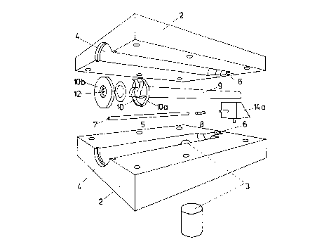
Fi- ug re 3: is a diagrammatic perspective exploded view of the nozzle
assembly in Figures
l and 2,
Fee 4: is a diagrammatic cross-section of a second embodiment of the present
invention,
and
Fi ure 5: is a cross-section through C-D of Figure 4, and
Fi- ug re 6: is a diagrammatic cross-section of a third embodiment of the
present invention,
and
F~ure 7: is a cross-section through E-F of Figure 6, and
F~: is a diagrammatic cross-section of a fifth embodiment of the present
invention,
and
Figure 9: is a diagrammatic cross-section of the embodiment shown in Figure 8.
9
2() 1'~'~'~9
Description of PreferredEmbodiments of this Invention
With respect to Figures 1, 2 and 3 there is provided a nozzle assembly
generally indicated by arrow 1 comprising a housing 2, a housing inlet 3, a
housing outlet 4, and a fluid conduit 5 situated within the housing 2.
The fluid conduit 5 is situated so that part of the conduit 5 is fixed at
point 6
relative to the housing 2. A liquid supply 14a (shown in Figure 3) is attached
to the fixed end of the conduit 5. The other free end 7 of the conduit 5 is
situated near the housing outlet 4. The conduit 5 has a short flexible section
8
that is situated near point 6. Alongside the conduit 5 is a circular wall 9
which defines the maximum axis of rotation of the conduit 5.
Near the housing outlet 4 are two sets of air dispersal means l0a and IOb. The
set adjacent to the housing outlet consists of an annular plate having cut
into
it a series of grooves 14. These grooves are tangential to the inner hole of
the
annulus as shown in detail in Figure 2a, their outer ends being within the
boundaries of the annulus's outer edge and are positioned in the housing
such that the fin bearing surface faces towards the housing outlet and
concentric with the grooved annular plate, the two being separated from each
other by the electrode ring assembly in such a way as to form two sets of
channels at right angles to the axis of the housing and contiguous with the
housing outlet.
Other versions of the embodiment shown in Figure I may only have finned air
dispersal means adjacent to the housing outlet.
~() 1'~'~'~9
Within the housing 2 and between the two annular rings 10a and 10b is the
aforementioned electrode-ring 12. A supply wire 13 is connected to the
electrode ring and to a power supply (not shown). The liquid supply 14a is
connE;cted to electrical earth.
In operation, air under pressure enters the housing inlet 3 in the direction
of
the arrows shown. The major portion of this air passes through the fins 10 of
the rearmost air dispersal means IOa inducing a swirling effect in the region
adjacent to the end of the fluid conduit 5 causing the end of the conduit to
rotate with respect to the longitudinal axis of the housing 2. The radius of
rotation is determined by wall 9. The smaller portion of the air passes into
grooves 14 of air dispersal means lOb emerging from their inward ends to
produce a swirling motion of that air adjacent to the swirling air from
between the fins of air dispersal means l0a but in the opposite sense. Liquid
supplied to the conduit 5 by liquid supply 14a is flung out as a result of the
centrifugal force created from its rotation. The air movement helps to shear
the droplets with the opposing air swirls counteracting excessive width of the
spray droplets swathe as they exit the housing outlet 4.
The electrode-ring 12 around the housing outlet 4 makes electrical contact
through the fluid as a result of the high potential difference between the
electrode-ring and the liquid. This causes a charge to be transferred to the
droplets which aids in the targeting of the spray.
Figures 4 and 5 illustrate a second embodiment of the present invention. The
construction of the housing 2 and the conduit 5 are essentially the same as in
the previous embodiment discussed. In this embodiment however the conduit
11
zcm~~s
is driven by a drive belt pulley system. A drive pulley 13a is situated
outside
the housing 2 and is connected by a drive belt 14 to a main pulley 15. A small
motor 17 is connected to the drive pulley. The main pulley 15 is situated
parallel to the front 16 of the housing 2 with the centre of the main pulley
15
being co-axial with the centre of the housing inlet 4. The main pulley 15 sits
on
a ball bearing race 19.
The conduit 5 passes accentrically through the main pulley 15 near its free
end 7. Drive pulley 13a, which is driven by motor 17 causes the main pulley 15
to turn via drive belt 14. The accentrical position of the conduit 5 means
that
movement of the main pulley 15 causes the free end 7 of the conduit 5 to
describe a circular motion. The speed of movement of the tube 5 can be altered
by changing the output of the motor 17.
The above embodiment does not have fins for the air dispersal means, instead
it has a perforated plate 18 situated near the drive pulley arrangement. The
perforated plate 18 also provides a base for the ball bearing race 19.
In operation, the motor 17 causes the conduit 5 to rotate, flinging out
droplets
of fluid from its end 7. Air under pressure is caused to enter the housing
inlet
3 after which it passes through the perforated plate 18 before mixing with the
droplets created from the conduit and expelling them from the housing exit 4.
Although this embodiment and the other embodiments discussed do not show
an electrostatic device, it should be appreciated that it is envisaged that
these
embodiments can be adapted to include same.
12
~( ) 1"~'~'79
A third embodiment of the present invention is illustrated in Figures 6 and 7.
In this embodiment the conduit 5 is accentrically fitted to a revolving disc
20.
The disc 20 has a central column 21 which is supported by a ball bearing race
22 with the diameter of the disc 20 being slightly less than the internal
diameter of the housing 2. Around the edge of the disc 20 are regularly spaced
fins 23. A perforated plate 24 which acts to support the ball bearing race 22
is
situated behind the disc 20.
In operation, aix under pressure is supplied through the housing inlet 3.
This air passes through the perforations 25 creating a force on the fins 23 of
the disc 20. This force causes the disc 20 to rotate which in turn causes the
free end 7 of the conduit 5 to circulate. The motion of airflow from the
housing
outlet 4 provides the desired shearing effect on the droplets flung from the
conduit 5.
A further embodiment of the present invention is illustrated in Figures 8 and
9. This embodiment differs from other embodiments in that there is no
housing as such and the air flow associated with the nozzle assembly is
provided the actual movement of the nozzle assembly itself. It is envisaged
that this embodiment will be best operated connected to a motive device such
as a tractor or an aircraft, especially as it is believed that this embodiment
is
the most suitable for horticultural spraying. Because of the imprecise nature
of horticultural spraying and desire to attain maximum coverage, it is
envisaged that a number of nozzle assemblies may be used within the one
spraying apparatus.
13
2~ 1~'~'~'7~
The construction of the fluid conduit 5 in this embodiment is similar to that
described before. The end 7 of the fluid conduit 5 is connected to a propeller
disk 35 which rests on a ball race. 36 attached to the wall 9 within which the
fluid conduit 5 is situated. Extending from the wall 9 is an electrode-support
pillar 37. This pillar extends above the propeller 35 and is angled so that an
electrode-plate 38 on the end of the pillar 37 is positioned in front of the
end 7 of
the fluid conduit 5. Both the pillar 37 and electrode-support plate 38 are
electrically insulated. Encircling the electrode-support plate is an electrode-
ring 39.
In operation, the end 7 of the fluid conduit 5 is situated so that fluid will
emerge from it in the same direction as air moving past the motive device to
which the nozzle assembly is attached. If the motive device is proceeding at a
fast enough speed, the air flow from the movement of the device will be
sufficient to turn the propeller 35 and hence the end 7 of the conduit 5 so
that
droplets are flung from the conduit 5 to create a spray cloud. Movement of the
propeller 35 also causes a shearing effect on the droplet cloud. The
positioning of the electrode-ring 39 ensures that the droplet cloud is evenly
charged.
If the motive device is too slow to provide the air flow necessary to achieve
the
desired effect, a further fan may be used to provide the additional air flow,
perhaps such as that found in air blast sprayers.
It can be seen that the present invention can be adapted for use in many
embodiments and can be used for a variety of applications. For instance, the
14
2~) 1'~'~'~9
present invention can be used for treatment of timber with sprays such as
antisapstain, horticultural spraying, painting and so forth.
Aspects of the present invention have been described by way of example only
and it should be appreciated that modifications and additions may be made
thereto in accordance with the invention as defined in the accompanying
claims.