Note: Descriptions are shown in the official language in which they were submitted.
20~786~
BACKGROUND OF THE INVENTION
F ield of the Invention
This invention relates generally to slide fasteners
and particularly to such a slide fastener which has a slider
lockable with a top end stop.
Prior Art
Slide fasteners have heretofore found extensive
application on a variety of garment articles such as
clothings, bags, tents, suitcases and the like. With a
slide fastener used for example on a bag while in transit,
it is not always necessary to fully lock the slider but
often desirable to keep it provisionally locked. A typical
example of such device is disclosed in Japanese Utility
Model Publication No. 46-17756 in which a latch provided on
a bag or the like has a pair of spring-biased pins
engageable in cavities formed in a slider having an integral
prong lockable with the latch. Since it is located on the
bag at a level, the latch is often positioned out of
alignment with the slider on the fastener at another level
the latch unless extreme care and tedious effort are paid.
SUMMARY OF THE INVENTION
With the foregoing difficulties of the prior art in
view, the present invention has for an object to provide a
slide fastener which has a slider easily engageable lockably
with and disengageable from a top end stop.
Another object of the invention is to provide a slide
fastener having a latch means incorporated either in a
-- 1 --
2017863
slider or in a top end stop, the latch having a
"provisional" and a "complete" lock function.
Another object of the invention is to provide a slide
fastener produced from a continuous fastener chain carrying
a plurality of alternate sliders and top end stops which are
movable on and attachable where desired on to the fastener
chain.
These and other objects of the invention will appear
clear from the following detailed description taken in
conjunction with the accompanying drawings which illustrate
by way of example some preferred embodiments.
According to the invention, there is provided a slide
fastener produced from a continuous fastener chain
comprising a pair of stringer tapes each carrying respective
rows of coupling elements along their respective inner
longitudinal edges, a plurality of alternate sliders and top
end stops both movable along the rows of coupling elements,
each of the sliders having an upper wing and a lower wing
joined at one of their ends by a neck and defining
therebetween a guide channel for the passage of the rows of
coupling elements and a wing extension extending forwardly
of the neck and having a lock cavity, the top end stop
having an upper wing extension and a lower wing extension
extending in parallel with each other and defining
therebetween a guide opening for receiving the wing
extension of the slider, the top end stop further
incorporating a latch movable into and out of the guide
2017863
opening and adapted to engage with the lock cavity, a spring
normally urging the latch toward the opening, and a lock
device for selectively locking and unlocking the latch.
BRIEF DESCRIPTION OF THE DRAWINGS
In the drawings in which like reference numerals refer
to like or corresponding parts throughout the several views:
FIG. 1 is a perspective view of a slide fastener
embodying the invention;
FIG. 2 is a plan view of the same;
FIG. 3 is a side elevational, partly sectional view of
a slider and a top end stop both slidably mounted on the
fastener of FIG. l;
FIG. 4 is a side elevational, partly sectional view of
the top end stop;
FIG. 5 is a top view, partly sectional, of a locking
means incorporated in the top end stop;
FIG. 6 is a view similar to FIG. 1 but showing the
slider and the top end stop coupled together;
FIG. 7 is a side elevational view of the slider and
the top end stop showing both in the process of being
~coupled together;
FIG. 8 is a side elevational view of the slider and
the top end stop (partly sectional) showing both immediately
prior to mutual coupling;
FIG. 9 iS a view similar to FIG. 8 but showing the
slider and the top end stop in separated disposition;
FIG. 10 iS a view similar to FIG. 8 but showing the
2017863
slider and the top end stop in coupled disposition;
FIG. 11 is a side elevational, partly sectional view
of a modified form of locking means;
FIG. 12 is a perspective view of the locking means of
FIG. 11;
FIG. 13 is a side elevational, partly sectional view
of the locking means of FIG. 11 showing the same in unlocked
disposition;
FIG. 14 is a view similar to FIG. 13 but showing the
locking means in locked disposition;
FIG. 15 is a diagrammatic plan view of an unfinished
slide fastener chain attached to a garment fabric;
FIG. 16 is a view similar to FIG. 15 but showing a
slide fastener finished with the slider and the top end stop
according to the invention; and
FIG. 17 is a diagrammatic perspective view of a bag to
which the slide fastener of the invention is applied.
DETAILED DESCRIPTION OF THE INVENTION
Referring now to the drawings and FIGS. 1 and 2 in
particular, there is shown a slide fastener 10 embodying the
present invention which comprises a pair of stringer tapes
11 and 12 each carrying on and along their respective inner
longitudinal edges a row of coupling elements 13, a slider
14 reciprocably movable along the coupling elements 13 to
open and close the slide fastener in a well known manner,
and a top end stop 15 similarly reciprocably movable along
the coupling elements 13 and adapted to be secured in place
2017863
on one end of the slide fastener 10 for limiting thereat the
movement of the slider 14.
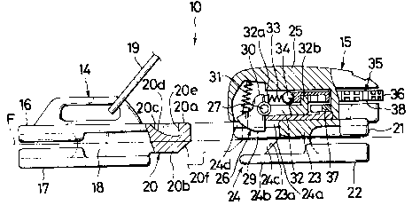
The slider 14 has an upper wing 16 and a lower wing 17
joined together at one of their ends by a neck 18 which is
commonly termed a "diamond" and defining therebetween a
guide channel for the passage of the slide fastener
stringers and a pull tab 19 adapted to move the slider 14
along the row of coupling elements 13.
The slider 14 has a one-piece wing extension 20
tapered and extending forwardly of the neck 18 and having an
upper surface 20a lying flush with the upper surface of the
upper wing 16 and a lower flat surface 20b offset from the
lower wing 17. The wing exrension 20 has a lock cavity 20c
formed in its upper surface 20a and cross-sectionally
defined by an arcuate bottom wall 20d and a vertical end
wall 20e at an leading end of the extension 20, the cavity
20cincreasing in depth progressively toward the vertical
wall 20e, as better shown in FIGS. 3 and 9. The wing
extension 20 is provided at its lower leading end portion
with an upwardly canted cam surface 20f for purposes
hereafter to be described.
The top end stop 15 has an upper wing 21 and a lower
wing 22 joined together by a neck 23 and includes a two-
piece wing extension 24 consisting of an upper wing
extension 24a and a lower wing extension 24b extending
integrally from the upper wing 21 and the lower wing 22
respectively and forwardly of the neck 23. The upper and
2017863
lower extensions 24a and 24b are in spaced parallel relation
to each other, defining therebetween a guide opening 24c for
receiving the wing extension 20 of the slider 14. The upper
wing extension 24a has an aperture 24d communicating with
the guide opening 24c.
The neck 23 of the top end stop lS has a downwardly
canted front end surface 23a disposed in the opening 24c for
face-to-face engagement with the canted cam surface 20f of
the slider wing extension 20.
Designated at 25 is a casing encompassing and attached
to the upper wing 21 of the top end stop 15.
A lock tumbler of latch 26 is pivotaly mounted through
the aperture 24d in the casing 25 to enter into and retract
from the guide opening 24c in the casing 25 of the top end
stop 15. More specifically, the tumbler 26 has an integral
transverse pin 27 received in vertically elongated guide
slots 28 formed in opposite side walls of the casing 25, as
better shown in FIG. 5, so that the tumbler 26 can rotate
and move vertically linearly as well along the guide slots
28. The lock tumbler 26 is provided at one end with an
integral lock prong 29 shaped in conformity with and hence
engageable with the lock cavity 20c of the slider 14 with a
tight fit in a manner hereafter to be described. At the
other end of the t~mbler 26 is an integral abutment 30.
The lock tumbler 26 is normally urged downwardly
toward the guide opening 24c by means of a first compression
spring 31 supported vertically in place within the casing 25
2017863
as shown in FIG. 3.
A slide bracket 32 has integral vertical ribs 32a and
32b protruding upwardly from opposite ends thereof and is
mounted in the casing 25 horizontally movably above the
upper wing 21 of the top end stop 15. The bracket 32 is
normally urged horizontally toward the tumbler 26 by means of
a second compression spring 33 having one end connected to
the ribs 32a and the other end connected via ball 34 to the
periphery of a first dial later described.
A dual dial device 35 comprises a first dial 36 and a
second dial 37 disposed in superposed relation to each other
and each rotatably mounted in the casing 25 and partly
protruding from a rear end thereof remote from the lock
tumbler 26. The first or upper dial 36 has a predetermined
number of equally spaced peripheral grooves 38 engageable
with the ball 34 connected to the second spring 33 so that
the dial device 35 can rotate resiliently intermittently.
The first dial 36 carries on its upper surface an array of
indicia such as numerical figures which are successively
exposed to view through a window 39 formed in the top wall
of the casing 35 as the dial is rotated, as shown in FIG.
6.
The first and second dials 36 and 37 are rotatable
relatively to each other by means of for example respective
confrontable pins (not shown), and have engaging peripheral
notches 36a and 37a, respectively, which are selectively
engageable with the vertical rib 32b of the slide bracket
Z017863
32.
With this construction, the sliders 14 and the top
end stop 15 are brought into coupling engagement with each
other by, for instance, inserting the wing extension 20 of
the slider 14 into the guide opening 24c in the top end stop
15 as shown in FIG. 7, in which instance, the slider 14 is
apt to tilt forwardly as it is pulled by the tab 19, and the
cam surface 20f of the extension 20 moves in sliding
engagement with the front end of the lower wing 22 of the
top end sop 15 and thus aids in smooth entry of the
slider wing extension 20, while the lock prong 29 is lifted
in contact with a leading upper surface portion of the wing
extension 20 against tension of the first spring 31 and
upon registry with the lock cavity 20c, the prong 29 is
urged by the spring 31 downwardly into the cavity 20c as
shown in FIGS. 8 and 10.
In this instance, the rows of coupling elements 13
which are located at a junction between the slider 14 and
the top end stop 15 are not coupled together but the
fastener stringers at that location are guarded by the wing
construction 24 of the top end stop 15 against being pulled
laterally outwardly which would otherwise take place when
severe lateral pull is exerted on the slide fastener.
When separating the slider 14 from the top end stop
15, they can be pulled away from each other with a tensile
strength great enough to overcome a compression strength of
the first spring 31 to release the lock prong 29 from the
2017863
lock cavity 20c, in which instance the lock spring 29 is so
released as the tumbler 26 rotates clockwise (as viewed in
the drawings) on its pin 27 until the lock prong 29 is
displaced clear of the guide opening 24c, as shown in FIG.
9. Immediately upon departure of the slider 14, the tumbler
26 is returned by the action of the first spring 31 to its
original position with the lock prong 29 protruding back
into the guide opening 24c.
The dual dial device 35 is utilized to permit and
prohibit movement of the lock tumbler 26 into and out of the
guide opening 24c in the top end stop 15. In a typical mode
of operation, the first dial 36 is rotated in either or one
direction until a selected combination of indicia appears in
the window 39 so that the engaging notch 37a of the second
dial 37 registers with the rib 32b of the slide bracket 32,
and the first dial 36 is then rotated in the opposite
direction until another selected combination appears in the
window 39 to bring the engaging notch 36a of the first dial
36 into registry with the rib 32b of the bracket 32. This
position represents an "unlock" or "provisional lock"
condition of the slider 14 with respect to the top end stop
15 as depicted in FIG. 8, in which condition the slider 14
can be drawn apart from the top end stop 15 with a pull just
strong enough to overcome the compression strength of the
first spring 31 in a manner already described.
Rotating the first dial 36 and/or the second dial 37
away from the above "unlock" position will shift their
2017863
respective notches 36a, 37b out of registry or alignment
with the bracket rib 32b and thereby bring the slider 14
into "complete lock" engagement with the top end stop 15, in
which position the lock prong 19 is not rotatable but
retained in locked engagement with the lock cavity 20c of
the slider wing extension 20, prohibiting separation of the
slider 14 from the top end stop 15. Since the lock tumbler
26 is vertically movable, the slider 14 and the top end stop
15 can be readily coupled by thrusting the slider wing
extension 20 into the guide opening 24c and locked together
immediately upon fitting engagement of the lock prong 29
with the lock cavity 20c.
FIGS. 11 - 14, inclusive, show a modified form of the
lock device incorporated in the top end stop 15, in which
there is provided a key-operated lock device in place of the
dial device 35 which has been already described. The key-
operated lock device 100 is shown, including a portion of
the slider wing extension 110 which is provided in its upper
surface with a relatively shallow, arcuately shaped lock
cavity llOa corresponding to the lock cavity 20c, the
remaining structural detailes of the slider 14 being
identical those already described and hence omitted.
A tumbler 200 is in the form of a lock roller 210
rotatably connected to one end of a first bracket 220, the
other end of which is pivotally connected to one end of a
second bracket 230. The lock roller 210 takes the place of
the lock prong 29 and is likewise normally urged by the
-- 10 --
2017863
first spring 31 downwardly toward the guide opening 24c in
the top end stop 15. The other end of the second bracket
230 is connected via a spring 240 to a crank arm 250
(corresponding to the slide bracket 32) having an elongated
horizontal engaging portion 250a at one end and a finger
portion 250b at the opposite end. The finger portion 250b
is offset from the horizontal engaging portion 250a so that
its end surface lies substantially flush with or slightly
above the upper surface of the second bracket 230.
A key-operated latch 260 having a top-like
configuration, as shown in FIG. 12, has a large-diameter
disc 270 and a small-diameter cam disc 280 formed integrally
but eccentrically with the disc 270. The cam disc 280 thus
has a first peripheral portion 280a coextensive with the
periphery of the large-diameter disc 270 and a second
peripheral portion 280b offset from the periphery of the
disc 270. The latch 260 is rotatably mounted in the casing
25 and has a key hole 260a in a portion of its upper surface
which is exposed through the casing 25 for engagement with a
key 290. The large-diameter disc 270 has a pair of
diametrically opposed peripheral notches 270a and 270b which
are adapted to receive the apex of a triangular leaf spring
300 secured to the inner wall of the casing 25.
Rotating the latch 260 with the key 290 in the hole
260a in one or the other direction for 180 will bring
either of the two notches 270a and 270b into locking
engagement with the leaf spring 300. When the latch 260 is
-- 11 --
2017863
rotated so as to register the notch 270a with the apex of
the leaf spring 300 as shown in FIGS. 10 and 11, the crank
arm 250 is positioned with its finger portion 250b held
apart from the upper surface of the second bracket 230 and
with its engaging portion 250a in abutting relation to the
second peripheral portion 280b of the cam disc 280, in which
position the slider 14 is unlocked with respect to the top
end stop 15 as the first bracket 220, hence the lock roller
210, is free to move away from the lock cavity 170a. By
rotating the latch 260 another 180 until the opposite notch
270b engages the leaf spring 300, the slider 14 and the top
end stop 15 are completely locked because the first
peripheral portion 280a of the cam disc 280 confronts and
pushes the crank arm 250 toward the lock roller 210 against
the tension of the spring 240 until the finger portion 250b
rides on the first bracket 220 past the second bracket 230
and prohibits the upward movement of the lock roller 210, as
shown in FIG. 14.
Having thus described the invention, it will be
understood that the slider 14 can be brought into and out of
engagement with the top end stop 15 efficiently and smoothly
and that the top end stop 15 according to the invention can
be freely moved along the rows of coupling elements 13 on a
slide fastener chain F shown in FIG. 15 and can be secured
thereto where described as by a threaded bolt 40 (FIG. 4) or
by an adhesive (not shown), as shown in FIG. 16, to define a
top end of an individual slide fastener 10 at which the
- 12 -
2017863
slider 14 stopped and held optionally in "provisional lock"
or "complete lock" engagement with the top end stop 15.
Another advantage of the invention is that a plurality
of sliders 14 and top end stops 15 may be mounted
alternately on a continuous length of slide fastener chain F
and can be cut to individual product lengths at the site of
garment manufacture.
The slider 14 and the top end stop 15 according to the
invention may be conveniently and suitably used on a bag B
as shown in FIG. 7.
Obviously, various modifications and variations of the
present invention are possible in the light of the above
teaching. It is therefore to be understood that within the
scope of the appended claims the invention may be practiced
otherwise than as specifically described.
As for an example, the guide opening 24c may be
provided in the slider 14 to which all the internal
structural details of the otp end stop 15 including the
latch 26 (200) and the dial device 35 (260) may be
transferred, and the wing extension 20 of the slider 14 may
be transferred to the top end stop 15, the arrangement being
that similar benefits of the invention may be attained.