Note: Descriptions are shown in the official language in which they were submitted.
2~1895
IMPROVED PRESSURE REDUCING AND CONDITIONING VALVES
Field of the Invention
The present invention is directed to improved pressure
reducing and conditioning valves for the simultaneous reduction of
both steam pressure and temperature. Specifically, the present
invention is directed to one-piece steam pressure reduction and
conditioning valves having trim sizes of between one and two
inches.
Background of the Invention
The present invention is directed to improved pressure
reducing and conditioning valves. Pressure reduction and
conditioning valves have been developed to simultaneously reduce
steam pressure and heat. Typically, pressure reducing and
conditioning valves are utilized for precise temperature and
pressure control in turbine by-pass, drying rolls, air preheater
coils, unit tie lines, process reactors, fan drives, compressor
drives, plant heating, fuel oil heating, evaporator supply, and
atomizing steam.
Pressure reduction valves reduce the pressure of incoming
steam. Steam conditioning valves operate by mixing superheated
steam under high pressure with desuperheated steam or atomized
water. A problem encountered with prior art pressure reducing and
conditioning valves is that they are complex and difficult to
control. A particular problem encountered with prior art
conditioning valves was that conditioning occurs in proximity to
~OZ'~~95
the valve member. Such conditioning valves require complex
structures to provide desuperheating steam or water directly into
the valve member, and often failed to achieve uniform distribution
of the atomized water or desuperheated steam. Prior art
conditioning valves also accumulated condensate downstream of the
valve members, and experienced water leakages. There has further
been a need for conditioning and pressure reducing valves having
trim diameters of approximately 1.0 to 2.0 inches. With the
reduced trim diameter, the plug, stem and water outlet tube can be
manufactured from a single piece, thereby facilitating manufacture
and reducing cost.
In view of the above, it is an object of the present invention
to provide pressure reducing and conditioning valves having trims
with small enough diameters to permit the valve stem and plug to
be fabricated from a single piece.
It is a further object of the present invention to provide
pressure reducing and conditioning valve incorporating controlled
steam leakage to heat the downstream side of the valve and to aid
in the removal of condensate.
It is yet a further object of the present invention to provide
pressure reducing and conditioning valves with improved water
leakage control.
The present invention is directed to pressure reducing and
conditioning valves having angled valve housings specifically
designed to minimize thermal stresses and fatigue as well as to
improve flow characteristics. Several embodiments of the invention
137.4 _
20178g~
incorporate an integral water proportioning system which
supplies desuperheating water and which is designed to provide
a fixed water to steam flow ratio proportional to the plug
position and which is a function of the valve stroke. The
invention further incorporates a system of labyrinths rather
than piston rings. The labyrinth contains 6-10 grooves to
reduce steam leakage between the trim and the bonnet for a
balanced plug version. In addition, because of the reduced trim
size, both plug and stem are manufactured out of a single piece.
The present invention, in its steam conditioning
embodiments, incorporates a novel injection nozzle which
uniformly distributes and atomizes the water within the high
turbulence valve outlet area. The nozzle incorporates a
swirling and accelerating chamber which helps to create a fine
and consistent spray pattern. This feature assures complete
atomization, and thereby optimizes evaporation and temperature
control.
Summary of the Invention
In accordance with one aspect of the present invention
there is provided a valve for reducing the pressure of steam
comprising: a valve body divided into first and second
chambers, said first chamber having an inlet port for the
introduction of superheated steam under high pressure into said
valve, said second chamber having an outlet port for expelling
depressurized steam out of said valve; an annular seat affixed
to the interior of said valve between said first and second
chambers; a hollow cylindrical cage being slidably matable with
said seat, said cage having perforations which permit the flow
of steam between said first and second chambers when said cage
is in a first position, said perforations being closed off to
prevent said flow of steam when said cage is in a second
- 3 -
20 17895
position; said cage having additional perforations which permit
a controlled leakage of steam from said first to second chamber
when said cage is in said second position, said controlled
leakage tending to heat said second chamber and remove
accumulated condensate therein; a bonnet having a cavity to hold
and support said cylindrical cage; means coupled to said cage
for adjusting said cage between said first and second positions;
and a back seat to provide a tight seal with said bonnet.
In accordance with another aspect of the present invention
there is provided a conditioning valve for simultaneously
reducing the pressure and temperature of incoming steam
comprising: a valve body divided into first and second
chambers, said first chamber having an inlet port for
introducing superheated steam under high pressure into said
conditioning valve, said second chamber having an outlet port
for expelling conditioned steam out of said conditioning valve;
an annular seat affixed to the interior of said valve body
between said first and second chambers; cylindrical valve means
slidably matable with said annular seat and extending between
said first and second chambers, said cylindrical valve means
having a plurality of perforations over a portion of its body
to permit the flow of steam between said first and second
chambers when the cylindrical valve means is in a first
position, said perforations being closed off from said flow of
steam when said cylindrical valve means is in a second position,
said cylindrical valve means having additional perforations to
permit a controlled leakage of steam when said cylindrical valve
means is in said second position; a water stem extending through
said cylindrical valve means and terminating in said second
chamber for transporting desuperheating water to said second
chamber, said stem being coupled to said cylindrical valve means
and slidably adjusting said cylindrical valve means between said
first and second positions; and nozzle means located at the
- 4 -
20 17895
terminal end of said water stem for injecting desuperheating
water into said second chamber to be mixed with steam entering
said second chamber, said nozzle means comprising a plurality
of tangentially extending conduits which generate a swirling
vortex of water and a hollow cylindrical sleeve extending into
said second chamber for transporting and accelerating said
swirling vortex of water into said second chamber.
In accordance with yet another aspect of the present
invention there is provided a valve for reducing the pressure
of steam comprising: a valve body divided into first and second
chambers, said first chamber having an inlet port for the
introduction of superheated steam under high pressure into said
conditioning valve, said second chamber having an outlet port
for expelling depressurized steam out of said valve; an annular
seat affixed to the interior of said valve between said first
and second chambers; a hollow cylindrical cage being slidably
matable with said seat, said cage having first perforations
which permit the flow of steam between said first and second
chambers when said cage is retracted in a first position, said
perforations being closed off to prevent said flow of steam when
said cage is in a second position; said cage having additional
perforations which permit a controlled leakage of steam from
said first to second chambers when said cage is in said second
position, said controlled leakage tending to heat said second
chamber and removing accumulated condensate therein; means
coupled to said cage for adjusting said cage between said first
and second positions; a bonnet having a cavity to hold and
support said retracted slidable cage and adjusting means; means
to facilitate slidable movement of said cage within said bonnet
cavity; a silencer cage coupled to said seat and extending into
said second chamber; and a sound absorbent metal foam having
approximately 90% free flow space contained within said silencer
cage.
- 4a -
B
2~1'7895
Brief Description of the Drawings
The foregoing summary, as well as the following detailed
description will be better understood when read in conjunction with
the Figures appended hereto. For the purpose of illustrating the
invention, there is shown in the drawings an embodiment which is
presently preferred, it being understood, however, that this
invention is not limited to the precise arrangement and
instrumentalities shown.
Figure 1 is a section view of the conditioning valve of the
preferred embodiment in a closed mode.
Figure lA is a section view of the conditioning valve of
Figure 1 in an open mode.
Figure 2 is a section view of the conditioning valve of the
preferred embodiment with a diffuser plate, held in place by a
welded in retaining ring.
Figure 3 is a section view of the nozzle and water stem of
the preferred embodiment.
Figure 3A is a section view of the nozzle of Figure 3.
Figure 3B is a plan view of the nozzle of Figure 3A.
Figure 3C is an elevated perspective view of the nozzle of
the preferred embodiment
Figure 4 is a section view of a balanced plug pressure
reducing valve of the present invention.
Figure 5 is a section view of a non-balanced pressure
reduction valve in accordance with the present invention.
137.4 _
2~1'?'89a
Figure 5A is an isolated section view of the perforated cage
of the non-balanced pressure reduction valve of Figure 5.
Figure 6 is a non-balanced tight plug pressure reduction valve
with silencer cage in accordance with the present invention.
Figure 7 is an enhanced view of a low noise silencer cage plug
for the pressure reduction valve of the present invention.
Figure 8 is a section view of the conditioning valve of Figure
2 with diffuser plate incorporating metal foam.
Figure 8A is an isolated view of an alternative configuration
for the conditioning valve of Figure 8.
Figure 9 is a section view of an alternative conditioning
valve which utilizes the metal silencing foam of the present
invention.
Detailed Description of the Preferred Embodiment
The present invention is described with reference to the
enclosed Figures, wherein the same numbers are used where
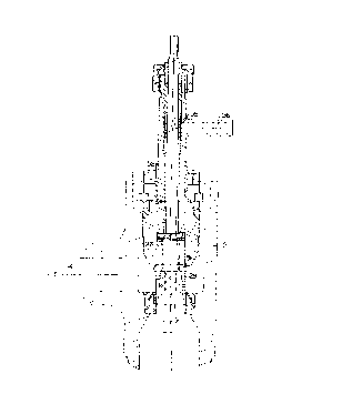
applicable. Referring to Figures 1 and lA, an elevated section
view of the conditioning valve of the preferred embodiment is
shown. Valve 10 comprises an outer casing 12 which has an inlet
port 14 for the injection of superheated steam and an outlet port
16 which expels desuperheated steam (and water) or reduced steam
pressure. The casing is die forged, but may be cast as well. The
casing therefore comprises an inlet chamber 18 and an outlet
chamber 20. The chambers are divided by an annular seat 22 formed
along an inwardly extending wall in the housing. The valve body
137.4 _ 6 _
201'795
is of angled design, and represents a safer, simpler and less
expensive approach than in-line designs.
The plug assembly 26 as shown, comprises respective upper and
lower cylindrical cage sections 27, 29 which mate with an annular
seat 22, dividing the inlet and outlet chambers. A seal fixes the
seat to the valve body. A flexible gap 22a permits thermal
expansion. The valve seat is hard faced 22b and must be
constructed to eliminate any leakage. The cylindrical cage 26 is
divided into an upper substantially solid plug portion 27 and a
perforated lower cage portion 29 through which superheated steam
flows from the inlet chamber 18. The upper substantially solid
plug portion contains apertures 25 so as to create a controlled
leakage of pressurized steam through to the outlet chamber 20, in
order to heat outlet chamber 20, thereby removing accumulated
condensate and preventing thermal shock. Holes 25 also have a
supplemental purpose. Because, as will be discussed in greater
detail below, the conditioning valve utilizes a labyrinth to
provide a controlled leakage, the pressure in the cavity 30a must
be relieved in order to balance the plug. A balanced plug requires
less energy to move, and therefore a smaller activator. The plug
and the seat assembly function as a valve to control the flow of
steam between the inlet and outlet chambers.
The valve housing has another opening 33 which supports a
bonnet 30 and water stem assembly 31. The bonnet is constructed
from heat resistent low alloyed carbon steel. The axial portion
of the bonnet contains a bore 34 which retains a water stem 52.
137.4 _ 7 _
v
~5
The bonnet 30 is retained within pressure sealed segmented
rings 42 by a locking nut 46, and is further supported by a
distance ring 48. Sealing is provided by the graphite packing
ring 50. The valve includes a back seat 51 which provides a
tight seal with the bonnet in the fully open position.
The upper cylindrical substantially solid plug 27 slides
through a cavity 30a in the bonnet 30. Plug 27 contains a
labyrinth 36 along its upper outer periphery 27a. The labyrinth
36 facilitates the sliding movement of the plug 27 within cavity
30a and also reduces superheated steam leakage from the inlet
14 into the cavity 30a. The water stem 52 extends through the
bore 34 of bonnet 30, axially through the interior of the
cylindrical cage 26, and into the outlet chamber 20. The water
stem 52 contains at its upper end metering holes 54 which
slidingly align with a water inlet conduit 56. Water stem 52
extends through opening 33 in the valve housing, and is
maintained at its upper end through packing as known in the art .
Water stem 52 and plug 27 are slidingly adjustable within the
bonnet cavity 30a. A perforated sleeve 58 surrounds the water
stem at the upper end. The sleeve perforations 58a are adjacent
to the upper end of water stem 52 and permit water to flow from
the water conduit 56 into the holes 54 in water stem 52. The
diameter of the valve seat is between 1.0 and 2.0 inches.
Because of the small diameter of the trim, the stem and plug
assembly are manufactured from a single piece.
Referring to Figure 2, the conditioning
valve of Figure 1 is shown including a
diffuser plate 60. Diffuser plate 60 is retained
g _
zo1~s95
in position by a retaining ring 62 which is welded into the body.
The water outlet nozzle is now described with reference to
Figure 3. Referring to Figures 3A-3C, the lower most portion of
the water stem 52 is shown. The water stem has an outlet 53 which
comprises a nozzle 64 which is retained at the lowermost portion
of the stem 52a. The nozzle 64 is inserted into the water stem,
and comprises a single piece. Nozzle 64 comprise an annular lip
66 which attaches to the end of the water stem 53 and an upper
portion comprising a swirler 68 and acceleration chamber 72.
Swirler 68 is covered by a washer 73. The swirler 68 contains a
plurality of tangential downwardly extending water passages 70
which tend to create a swirling vortex of water. The vortex of
water exits a hollow acceleration cylinder 72 affixed to the end
of the nozzle where it enters the outlet chamber 20.
The operation of the conditioning valve invention is now
described with reference to Figures 1, lA, 2 and 3-3C. Referring
to Figure lA, the conditioning valve of the present invention is
shown in the open position. Stem and plug assembly are pulled
upward. The upward movement accordingly pulls valve stem 52 and
plug 27 into bonnet cavity 30a via the labyrinth 36. Steam flows
into the body 12 through inlet port 14 over seat 22 and through the
perforations in perforated cage 29 which provides pressure
reduction. The steam then flows down through seat 22 and enters
the outlet chamber. In the fully open position, the plug shoulder
butts the back seat at the lower end of the bonnet and eliminates
steam flow to the cavity 30a.
137.4 _ g
~~017895
Simultaneously, the water holes 54 in the upper portion of
the stem assembly 40 are aligned with perforations 58a and water
inlet conduit 56. Cooling water is injected down the stem and out
the nozzle 64. Labyrinth 36 functions to reduce superheated steam
leakage from the inlet chamber to the bonnet cavity 30a . The steam
and water mix in an area of a high degree of turbulence and the
temperature is reduced. By gradually moving the stem and plug
upward, a precise number of perforations are open in the cage 29,
and upper stem 54. The amount of desuperheating water injected is
therefore directly proportional to the amount of steam flowing
through the valve.
Because of the unique design of the above described water
nozzle and the fluid dynamics of the valve, the water mixes
thoroughly with the steam in outlet chamber 20 without impinging
on the inner walls of the valve body. Steam, reduced in both
pressure and temperature, is discharged into the downstream piping
fully conditioned, so as not to cause harm to downstream
instrumentation machinery, or valves. In the fully open position,
the plug shoulder hits the back seat at the lower end of the bonnet
and eliminates steam flow to the cavity 30a. The labyrinth grooves
can collect small particles of dirt and salt which are found in
steam flows. The labyrinth builds down the high steam pressure and
provides a controlled leakage. The labyrinth eliminates the piston
rings, inherent ring costs and possible wear problems.
Figure 1 discloses the stem and cage plug assembly in the
closed position. As shown, the water stem 52 and plug 27 are
137.4 - 10 -
2~D1'7835
pushed downward and superimposed over the annular seat 22. Plug
27 contains a limited number of openings which permit a controlled
leakage of steam through to the outlet chamber. The controlled
leakage heats the outlet chamber 20 and operates both to remove
accumulated condensate and to prevent thermal shock when the valve
opens as in Figure lA. The holes 54 in upper water stem are pulled
down away from the water inlet conduit and the perforated water
sleeve 58. Thus, none of the holes in the inner cage are exposed
to the steam or water flow.
Figures 4-7 illustrate additional embodiments of the preferred
embodiment. The embodiments of Figures 4-7 are directed to
pressure reduction valves and incorporate balanced plugs and non-
balanced tight plugs without silencer cages.
Figure 4 illustrates a balanced pressure reducing valve. The
valve of Figure 4 is identical to that of Figure 1 except that it
does not include the water steam conditioning apparatus . The valve
incorporates the single piece valve and stem assembly of Figures
1 and lA. The plug 27 further includes a labyrinth 36 which
facilitates its movement through the bonnet 30 and reduces the
steam leakage. The, labyrinth groves can collect small particles
of dirt and salt which are found in steam flows . The labyrinth
builds down the high steam pressure. The labyrinth eliminates the
piston rings and the inherent ring cost, and possible wear
problems. In operation the plug is retracted by stem into a bonnet
cavity 30a, exposing perforated cage portion 29. When closed, the
137.4 - 11 -
-. 201"~89~
plug 27 permits a constant leakage of steam into the outlet chamber
20.
Figures 5 & 6 illustrate non-balanced tight plug designs.
The plug of Figure 5 consists of a single cylindrical perforated
retractable plug 76. The plug has a solid top section 78 which
mates with seat 22 to provide a tight seal. As shown more
particularly in Figure 5A, solid top section 78 serves as a plug,
and is retracted by stem 80 to expose its perforated outer casing
76. The holes on the. perforated outer overlap. The overlapping
is necessary to get a smooth and ripple free linear flow
characteristic. In addition, the top row of holes is smaller.
After stroking the valve over a dead band (typically 1/25"), the
f luid starts to f low through the smaller top holes in the plug .
Figure 6 shows the plug of Figure 5 with a silencer cage 82 which
forms an integral part of the seat 22 and extends into outlet
chamber 20. The silencer cage 82 is constructed from heat
resistant low alloyed carbon steel. The bonnets in Figures 5 & 6
do not contain cavity 30a to receive the retracted valve assembly.
The respective plugs are activated by a stem 80 which is retained
within the bonnet and guided by a stellite guide bushing 84 which
also provides for a backseat in fully open position.
Figure 7 illustrates a non-balanced tight plug with a low
noise silencer cage 90. Like the embodiments of Figures 5 and 6,
the plug of Figure 7 has solid top section 78 which provides a
tight seal with seat 22.
The plug is constructed of martensitic steel and contains a
137.4 - 12 -
-2opa95
plurality of apertures 88 for steam. The silencer section has a
perforated casing constructed from high temperature resistant
martensitic stainless steel and extends into the outlet chamber 20.
The plug and silencer section are welded together 89 by an electron
beam. The silencer 90 is filled with stainless steel metal foam
97 which contains 90~ free flow space. The pressure loss in the
foam is therefore very small. In operation, the metal foam with
its thousands of small flow paths splits the high energy single
flow into many low energy jets and drastically reduces sound
pressure levels in the frequency range 30-15, 000 HZ. In operation,
the perforated plug is lifted by the stem 80 to permit steam to
move between the inlet and outlet chambers through the silencer 90.
The silencer is constructed from metal foam made of material
such as nickel and nickel chrome. The material has several
advantages. Among these, are that it splits-up the single flow jet
into hundreds and thousands of low energy jets. Secondly, it
provides a low pressure drop. Third, the material has a high
porosity and is extremely light. Fourth, it is corrosion-resistant
and can be compacted to fit into almost any construction.
Figure 8 shows the steam conditioning valve of Figures 1 and
2 with a retaining ring. The retaining ring supports a layer of
the metal foam 92 of the present invention. In an alternative
embodiment shown in Figure 8A, the foam is sandwiched between the
threaded ring 94, diffuser plate 96 and diffuser ring 97.
Figure 9 illustrates the use of the metal foam 98 in an
alternative conditioning and pressure reducing valve. In
this embodiment, water
- 13 -
_. 20~.~89~
injection enters through the outlet chamber 100.
It will be recognized by those skilled in the art that changes
may be made to the above-described embodiments of the invention
without departing from the broad inventive concepts thereof. It
is understood, therefore, that this invention is not limited to the
particular embodiment disclosed, but it is intended to cover all
modifications which are within the scope and spirit of the
invention as defined by the claims appended hereto.
137.4 - 14 -