Note: Descriptions are shown in the official language in which they were submitted.
~91~896
IMPROVED CONDITIONING VALVE
Field of the Invention
The present invention is directed to an improved
conditioning valve for the simultaneous reduction of both steam
temperature and pressure. In particular, the present invention
is directed to a steam conditioning valve which incorporates
one of a plurality of novel nozzle configurations.
2~1~'896
Background of the Invention
The present invention is directed to an improved
conditioning valve. Conditioning valves have been developed
to simultaneously reduce steam heat and pressure. Conditioning
valves eliminate the need for conventional pressure reducing
valves and desuperheaters and their separate temperature and
pressure measurement-control loops. Typically, conditioning
valves are utilized for precise temperature and pressure
control in turbine by-pass, drying rolls, air preheater coils,
unit tie lines, process reactors, fan drives, compressor
drives, plant heating, fuel oil heating, evaporator supply, and
atomizing steam.
Steam conditioning valves operate by mixing superheated
steam under high pressure with desuperheated steam or atomized
water. A problem encountered with prior art valves was that
they were complex and difficult to control. An additional
problem encountered with prior art conditioning valves was that
conditioning occurred in proximity to the valve member. Such
conditioning valves required complex structures to provide
desuperheating steam or water directly into the valve member,
and often failed to achieve uniform distribution of the
atomized water or desuperheated steam. Moreover, the greatest
area of turbulence often occurs on the outlet side of the
valve, downstream of the valve member.
137.3
~~D1"~896
The present invention is directed to a conditioning valve
having a smoothly shaped valve housing specifically designed to
minimize thermal stresses and fatigue as well as to improve
flow characteristics. The smooth flow path shaping avoids flow
separation and undesirable vortex streets and therefore
maintains a low sound pressure level. The invention
incorporates an integral water proportioning system which
supplies desuperheating water and which is designed to provide
a fixed water to steam flow ratio proportional to the plug
position which is a function of the valve stroke. The valve of
the present invention is able to respond to large changes in
load while maintaining precise temperature control.
The present invention further incorporates novel injection
nozzles which uniformly distribute the water within the high
turbulence area. The features provided by the nozzles of the
present invention assure complete atomization, and thereby
optimize evaporation and temperature control. Noise reduction
is enhanced by injecting water into the area of highest
turbulence.
137.3 _ 3 _
2017896
Summary of the Invention
In accordance with one aspect of the present invention there
is provided a conditioning valve for simultaneously reducing the
pressure and temperature of incoming steam, comprising, a valve
body having an interior divided into first and second chambers,
said first chamber having an inlet port for introducing a flow of
superheated steam under high pressure into said conditioning valve,
said second chamber having an outlet port for expelling conditioned
steam out of said conditioning valve; an annular seat affixed to
the interior of said valve body between said first and second
chambers; a perforated outer casing affixed to said annular seat
and permitting the flow of steam into said second chamber, said
perforated outer casing extending from said annular seat into the
second chamber; a cylindrical valve means slidably matable within
said perforated outer casing and extending between said first and
second chambers, said valve means permitting the flow of steam
between said first and second chambers when said inner cage is in
a first position and preventing said flow of steam when said inner
cage is in a second position; a water stem extending through said
cylindrical valve means and terminating in said second chamber for
transporting desuperheating water to said second chamber, said stem
being coupled to said cylindrical valve means for slidably
adjusting said cylindrical valve means between said first and
second positions; a water valve operatively coupled to an upstream
portion of said water stem for controlling the flow of
desuperheating water into said water stem, the water valve opening
when said inner cylindrical cage is in the first position and
closing when said inner cylindrical cage is in the second position;
- 4 -
2017896
and a nozzle located at the terminal end of said water stem for
injecting atomized water into said second chamber to be mixed with
steam entering said second chamber, said nozzle comprising a plug
end and a tubular sleeve within said terminal end of said water
stem so as to form an annular flow channel therebetween, said
tubular sleeve having a plurality of tangential openings adjacent
said plug end to generate a swirling stream of water exiting said
annular channel into said second chamber.
In accordance with another aspect of the present invention
there is provided a conditioning valve for simultaneously reducing
the pressure and temperature of incoming steam comprising: a valve
body having an interior divided into first and second chambers,
said f first chamber having an inlet port for introducing superheated
steam flow under high pressure into said conditioning valve, said
second chamber having an outlet port for expelling conditioned
steam out of said conditioning valve; an annular seat affixed to
the interior of said valve body between said first and second
chambers; a perforated outer casing affixed to said annular seat
and extending into said second chamber, said outer casing
permitting the flow of steam into said second chamber; movable
cylindrical valve means slidably matable within said annular seat
and said perforated cylindrical outer casing, said cylindrical
valve means extending between said first and second chambers, said
cylindrical valve means having a plurality of openings over a
portion of its body to permit the flow of steam between said first
and second chambers when said valve means is in a first position,
said openings being closed off from said flow of steam when said
cylindrical valve means is in a second position; a water stem
20178g~
extending axially through the center of said cylindrical valve
means, said water stem having a terminal end in said second
chamber, said water stem transporting desuperheating water to said
second chamber, said stem further being coupled to said cylindrical
valve means and slidably adjusting said cylindrical valve means
between said first and second positions; and nozzle means located
at the terminal end of said water stem for injecting atomizing
water into said second chamber to be mixed with steam entering said
second chamber.
In accordance with yet another aspect of the present invention
there is provided a conditioning valve for simultaneously reducing
the pressure and temperature of incoming steam comprising: a valve
body having an interior divided into first and second chambers,
said first chamber having an inlet port for introducing a flow of
superheated steam under high pressure into said conditioning valve,
said second chamber having an outlet port for expelling conditioned
steam out of said conditioning valve; an annular seat affixed to
the interior of said valve body between said first and second
chambers; a perforated cylindrical outer casing affixed to said
annular seat and extending into said second chamber, said outer
casing permitting the flow of steam into said second chamber; a
cylindrical valve means slidably matable within said annular seat
and said perforated cylindrical outer casing and extending between
said first and second chambers, said cylindrical valve means having
a plurality of perforations over a portion of its body to permit
the flow of steam between said first and second chambers when the
cylindrical valve means is in a first position, said perforations
being closed off from said flow of steam when said cylindrical
- 5a -
~i
~
2017896
valve means is in a second position; a water stem extending through
said valve means, said water stem having a terminal end within said
second chamber for transporting desuperheating water to said second
chamber, said stem being coupled to said cylindrical valve means
and slidably adjusting said cylindrical valve means between said
first and second positions; and nozzle means located at the
terminal end of said water stem for injecting atomized
desuperheating water into said second chamber to be mixed with
steam entering said second chamber, said nozzle means comprising a
tubular sleeve coupled with an angled plug end, said tubular sleeve
being inserted into said terminal end of said water stem and mating
therewith so as to form a flow path between said water stem and
said plug end, said plug end and said terminal end forming a flow
channel, said tubular sleeve having openings adjacent to said plug
end to allow water to exit into said second chamber.
- 5b -
~~1."~a~~
_ . r
Brief Description of the Drawings
The foregoing summary, as well as the following detailed
description will be better understood when read in conjunction
with the figures appended hereto. For the purpose of
illustrating the invention, there is shown in the drawings an
embodiment which is presently preferred, it being understood,
however, that this invention is not limited to the precise
arrangement and instrumentalities shown.
Figure 1 is a section view of the conditioning valve of
the preferred embodiment.
Figure 2 is an enhanced section view of the water stem and
outlet of the preferred embodiment.
Figures 3 and 4 are enhanced section views of the
atomizing nozzles of the preferred embodiment.
Figures 5 is a section view of the conditioning valve of
the preferred embodiment during operation.
Figure 6 is a section view of an alternative nozzle
embodiment.
Figure 6A is a planar view of the alternative nozzle
embodiment along line A-A of Figure 6.
Figure 7 is a section view of a second alternative nozzle
for the preferred embodiment.
Figure 7A is a plan view of the second alternative nozzle
along line A-A of Figure 7.
Figure 7B is a plan view of the second alternative
embodiment along line B-B of Figure 7.
137.3 _
~~1'~89~
Figure 8 is a section view of a fourth alternative
atomizing nozzle.
Figure 8A is a planar view of the fourth alternative
nozzle embodiment along line A-A of Figure 8.
Figure 8B is a planar view of the fourth alternative
nozzle embodiment along line B-B of Figure 8.
Figure 8C is a planar view of the fourth alternative
nozzle embodiment along line C-C of Figure 8.
Figure 9 is a fifth embodiment for the nozzle for the
preferred embodiment.
Figure 9A is a plan view of the fifth alternative nozzle
along line A-A of Figure 9.
Figure 9B is a plan view of the fifth alternative nozzle
along B-B of Figure 9.
Figure 10 is a section view of a third alternative nozzle
for the preferred embodiment.
Figure l0A is a planar view of the third alternative
nozzle embodiment of Figure 10.
Figure lOB is a section view of the third alternative
nozzle embodiment along line B-B of Figure 10.
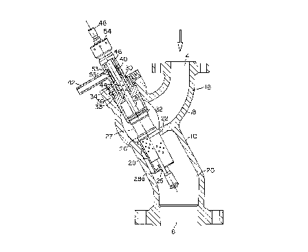
Figure 11' is a section view of an angled steam
conditioning valve with a pressure sealed bonnet.
Figure 12 is a broken away elevated view of an angled
steam conditioning valve with a bolted bonnet.
r
137 . 3 _ 7
2017896
Detailed Description of the Preferred Embodiment
The present invention is described with reference to the
enclosed figures, wherein the same numbers are used where
applicable. Referring to Figure 1, an elevated section view of
the conditioning valve of the preferred embodiment is shown.
Valve 10 comprises a valve body 12 which has had an inlet
port 14 for the injection of superheated steam and an outlet
port 16 which expels desuperheated steam (and water). The
valve body 12 therefore comprises an inlet chamber or first chamber 18
and an outlet chamber or second chamber 20. The chambers are divided by
an annular seat 22 formed along an inwardly extending wall in the housing.
The seat assembly supports two concentric perforated cylindrical
cages (valve means). The inner cylindrical cage 26 is divided into an
upstream solid portion 27 which functions as the plug and a perforated
lower portion 29 through which superheated steam flows from the inlet
chamber. The outer cylindrical cage or perforated outer casing 28
extends into outlet chamber 20 and is superimposed over the
inner cylindrical cage 26. Outer cylindrical cage 28 also
contains perforations through which desuperheated steam enters
the outlet chamber 20. Outer cylindrical cage 28 mates with
annular seat 22~ and is arced inward 28a to break standing
waves. Both cages and the seat assembly function as a valve to
control the flow of steam between the inlet and outlet
chambers.
The valve housing has another opening 33 which supports a
bonnet 30 and water stem assembly 31. The inner cylindrical
_ g _
__ 2017896
cage 26 slides within bonnet 30. Piston rings 32 surrounding
plug 27 and maintain a seal. The bonnet 30 is maintained
within the housing by segment ring 34 and pressure seal gasket
36. Pre-stress ring further supports bonnet 30.
A water stem 40 extends through the center of bonnet 30,
axially through the interior of cylindrical cages, and into the
outlet chamber 20. The water stem 40 contains at its upstream end
holes 44 which slidingly align with a water inlet conduit 42.
Water stem 40 extends through opening 33 in the valve housing,
and is sealed at its upper end through packing 46. Water stem
40 and plug 27 are slidably adjustable within the bonnet 30 by
means of stem and plug assembly 48 i.e. by moving 48 up and
down. A retaining ring 54 holds a gland (not shown) against
the packing nut (not shown). The stem and plug assembly 48 can
be moved longitudinally by any conventional mechanical device.
A perforated sleeve 53 surrounds the water stem at the upper
end. Perforations 55 are adjacent to the upper end of water
stem 40 and permit water to flow from the water conduit into
the holes 44 in water stem 40.
The water outlet nozzle of the first embodiment is now
described with reference to Figures 2, 3 and 4. Referring to
Figure 2, the lower most portion of the water stem 40 extending
through cylindrical cages 26 and 28 is shown. The water stem
has an outlet which comprises a nozzle 56 which is retained
within a terminal end or outer sleeve 58 which is integral with stem 40
and located at the downstream end portion of the stem 40. Nozzle 56
- 9 -
2017896
comprises a sequence of outwardly extending outlet conduits 62
which are beveled downward and which direct jets of water
outward against the interior wall of the sleeve 58. Cooling
water exits an annular channel 66 formed between the nozzle 56
and the sleeve 58.
The operation of the present invention is now described
with reference to Figures 1 and 5. Referring to Figure 5, the
conditioning valve of the present invention is shown in the
open position. Stem and plug assembly 48 is pulled upstream.
This pulls valve stem 40 and inner cage 26 toward bonnet 30.
Steam flows into the body 12 through inlet port 14 over seat 22
and through the perforations in inner cage 29 which provides
initial pressure reduction. The invention incorporates a small
passage 25 between the outer cylinder 28. This creates a
suction effect at the nozzle end. The steam then flows through
the inner cage 29 and enters the outlet chamber through
perforated outer cage 28 which provides a second controlled
pressure reduction. Simultaneously, the water holes 44 in the
upstream portion of the stem assembly 40 are aligned with
perforations 55 and water inlet conduit 42. Cooling water is
injected down the stem and out the atomizing nozzle 56. The
steam and water mix and the temperature is reduced. By
gradually moving the stem upward, a precise number of
perforations are open in the inner cage 26, and upper stem 42.
The amount of desuperheating water injected is therefore
- 10 -
A
201789fi
directly proportional to the amount of steam flowing through
the valve.
Because of the unique design of the above described water
nozzle and the fluid dynamics of the valve, the atomized water
mixes thoroughly with the steam in outlet chamber 20 without
impinging on the inner walls of the valve body. In operation
the water forms a film on the inner surface of sleeve 58. The
high velocity steam boundary layer along the walls of outlet
chamber 20 avoids the formation of a water spray to the wall
and avoids water impingement. Steam, reduced in both pressure
and temperature, is discharged into the downstream piping fully
conditioned, so as not to cause harm to any instrumentation,
machinery, valves or elbows.
Figure 1 discloses the stem and cage plug assembly in the
closed position. As shown, the water stem 40 and inner
cylindrical cage 26 are pushed downstream and the non-perforated
portion of the inner cylindrical cage 26 is superimposed over
the annular seat 22. The holes in upper water stem are pulled
down away from the water inlet conduit and the perforated water
sleeve 53. Thus, none of the holes in the inner cage upper
stem are exposed' to the steam or water flow.
The present invention has been disclosed in the context an
in-line valve in which the inlet and outlet ports lie along the
same plane of reference. However the benefits of the present
invention are equally applicable in an angled valve such as
that disclosed in Figures 11 and 12. The valve of Figure 11
- 11 -
n
2017896
incorporates a pressure sealed bonnet. The valve of Figure 12
incorporates a bolted bonnet 30a and silencer plate 61. Both
embodiments operate in an identical manner as that discussed in
Figures 1-5.
In addition to the nozzle embodiment disclosed above in
Figures 2-4, the present invention may also be utilized with
one of the five alternative nozzle embodiments disclosed in
Figures 6-10. Figures 6 and 6A illustrate a first alternative
nozzle embodiment. The nozzle of Figure 6 comprises a plug 68
which is inserted into the end of the water stem sleeve 58.
The plug 68 includes a hollow tubular sleeve 70 which extends
into the water stem sleeve 58 and a plug end section 72 located
proximate to the outer sleeve 58, and which forms a water flow
surface 74. An annular flow channel 76 is thus formed between
the outer sleeve of the water stem and the plug end. The
tubular sleeve 70 is connected to the inner walls of the water
stem by a thread 75 and forms an internal water passage between
the water stem and plug end. As shown in the plan view of
Figure 6A, the tubular sleeve contains multiple openings or downstream
extending tangential conduits 78 located near the plug end. The
conduits connect' the inside of the sleeve 70 with the annular
channel 76.
The water flows down the water stem and enters the inside
channel formed by tubular sleeve 70. The water then enters the
tangentially extending conduits 78 where it is radically and
tangentially accelerated into channel 76, imparting a high
- 12 -
201789
velocity swirling motion. During low water flow conditions,
the water does not completely fill channel 76, but attaches to
the inner wall of 58, and is discharged across the outer lip
58a. As flow increases, water accelerates through channel 76
and discharges across the controlled opening 76b.
Figures 7-7B illustrate a second alternative nozzle
embodiment. As with the embodiment in Figure s 6 and 6A, the
embodiment of these Figures similarly utilize a plug which is
inserted into the water stem. The plug contains an interior
hollow sleeve 79 which mates with the water stem but narrows
and terminates at a side wall defining a seat 81. A spring activated
displaceable valve member or piston 80 and rod 82 arrangement operate
create a back pressure to control the flow of water out of the water
stem. The piston 80 and rod 82 are slidably retained within a
cylindrical piston chamber 84 which is bored into the plug end.
The plug end further contains a bore 86 which facilitates the
longitudinal movement of the rod out of the plug end and into
outlet chamber 20. The bore 86 contains a labyrinth 88 which
catches dirt and reduces leakage. The piston valve is biased
upward by a spring 90 housed within the cylindrical piston
chamber 84 and lies flush against seat 81 of a water channel
contained within the water stem, thereby preventing water flow.
During operation, as water pressure in the water stem
builds, the biased piston valve 80 is thrust downward into the
cylindrical piston chamber and away from the seat 81 (see
hashed lines A). As the piston valve is thrust downward by the
- 13 -
201"7896
water pressure, it sequentially exposes ducts 91 and a
plurality of tangential channels 93 (Figures 7A and 7B) bored
longitudinally into the walls of the plug. The sides walls of
the piston valve also contain a labyrinth 94 to reduce leakage
and catch dirt. As the downward thrust of the piston valve 80
continues, desuperheating water exits sequentially out the
ducts 91 and if the water pressure from the valve stem is high
enough, out the tangential flow channels 93 and into the
annular channel 97 formed between the plug end and the water
stem. The plug end further contains a narrow horizontal
conduit 96 extending between the piston chamber and annular
channel to permit excess water trapped within cylindrical
piston chamber 84 to exit the system.
In both the embodiments of Figures 6 and 7, then, a
swirling pattern is used in combination with an annular
channel. The swirl pattern is developed by tangential orifices
discharging the water from an interior plug chamber onto the
inside of the water stem sleeve 58. At low to intermediate
flow conditions, the radial velocity component developed by the
change in direction of the fluid, causes the fluid to flow
along the inside surface of the water tube and discharge off
the outer discharge edge in a uniform pattern. At higher
flows, the annular gap becomes the restriction. A spray
pattern is accordingly developed by a combination of the swirl
velocity and the acceleration through the annular orifice.
137.3 - 14 -
2017896
Three additional nozzle configurations are disclosed in
Figures 8, 9, and 10. In each of these embodiments, a vortex
nozzle is utilized. Figure 10 illustrates a vortex nozzle with
tangential angular feed ports. In this embodiment and in the
embodiments of Figures 8 and 9, the nozzle plug 99 is inserted
into the water stem. The nozzle plug 99 contains a plug end 98 which
attaches to and seals off the terminal end of the water stem. With
particular reference to Figure l0, the plug comprises a cavity portion
100 and a solid body 102 which extends up into the water stem. The solid
body portion contains flow channels 104 located on its outer
periphery. Tangential conduits 105 connect the flow channels
104 to the top of the cavity 100. A nozzle piece 106 is
attached to the end of plug. The nozzle piece 106 comprises a
beveled inlet 108 and a hollow cylindrical opening 110.
During operation, water descends down the water stem.
When the water flow reaches the solid body 102 it is directed
toward the four rectangular flow channels 104. The water flows
down the channels 104 and into the tangential conduits 105.
The tangential conduits 105 create a swirling vortex 109 of
water within the cavity which exits through the hollow
cylindrical opening 110 of the nozzle.
Figures 8-8C illustrate a similar nozzle to that disclosed
in Figure 10. In Figure 8, the end plug and nozzle are
attached in an identical manner to that of the embodiment in
Figure 10. This embodiment utilizes a spring activated piston
valve 112 and valve seat 115 which separates respective upper
- 15 -
201789fi
and lower flow chambers 114, 116. The piston valve 112 and has a
rod 113 which extends up into the water stem and is enclosed
within a hollowed sleeve section which defines a piston chamber
118. The rod 113 is coupled to a dome shaped end piece 120
which is biased upward against the valve seat 115 by a biasing means or
spring 124 situated within the hollowed piston chamber 118.
The rod is further guided by guiding walls which extend from
the upstream walls of the upstream chamber. The guides contain a
labyrinth 119 to catch dirt and minimize leakage between the
piston chamber 118 and upper flow chamber 114. The piston
shaped valve member is attached to the end other end of the rod
and separates the upstream and downstream chambers. The upstream chamber
is thus defined between the walls of the end plug, the guides
and the piston. The downstream chamber is situated between the
piston valve and the nozzle. Four tangential conduits 121
connect the upstream chamber with channels 104.
During operation, water flows down the water stem and is
directed by the dome-shaped end piece 120 into the four
rectangular flow channels 104. The water then flows into the
tangential conduits 121 and enters the upstream chamber 114 as a
swirling vortex. As the water pressure in the upstream chamber
builds, the biased valve member is thrust downward (downstream) thereby
permitting water to exit the upstream chamber as a swirling vortex
and enter the lower chamber 116. The water then exits through
nozzle 110. This valve prevents flashing in the water stem.
- 16 -
'2017896
Figures 9-9B illustrate a two stage spring loaded vortex
nozzle. This embodiment is identical to that disclosed above
in Figure 8 except that it incorporates additional tangential
conduits 122 in downstream chamber 116. The embodiment of Figure 7
therefore provides a constant linkage between the rectangular
flow channels 104 and the lower chamber 116. During periods of
low water flow, there is a constant vortex of water through the
nozzle via tangential conduits 122. As the pressure builds in
the upstream chamber the piston valve is thrust downward off the
valve seat, additional flow between the upstream and downstream
chambers occurs. This embodiment thus creates a two stage
injector valve.
The spray patterns of the vortex nozzles of Figures 8, 9
and 10 are controlled by the design proportions of the nozzle
and orifice, the radial acceleration developed by the
tangential inlet ports and the exit configurations. Vortex
nozzles are tolerant of dirt and particulate matter due to
their large orifices. The maximum flow capacity is less than
can be accomplished in a swirl nozzle of the same size.
It will be recognized by those skilled in the art that
changes may be made to the above-described embodiments of the
invention without departing from the broad inventive concepts
thereof. It is understood, therefore, that this invention is
not limited to the particular embodiments disclosed, but it is
intended to cover all modifications which are within the scope
- 17 -
n
~a1?89~
and spirit of the invention as defined by the claims appended
hereto.
137.3 - 18 -