Note: Descriptions are shown in the official language in which they were submitted.
~dl~.'~~9°~~~a
_1_
WINDOW FOR ACOUSTIC WAVE FORM
AND METHOD FOR MAKING
FIELD OF THE INVENTION
This invention relates to windows for the
passage of a desired acoustic wave form, and more
specifically to such windows employed in submerged
liquid service such as underwater service. More
particularly, this invention relates to sonar
windows such as domes for use on suxface and
submergible vessels in both the military and
commercial arena.
BACKGROUND OF THE INVENTION
Acoustic windows such as sonar domes for
use in transmitting or receiving acoustic wave form
signals in a liquid environment are known.
Traditionally, these windows have consisted of a
single thickness of a metal such as steel that may
optionally have been covered by a biologically
active substance such as a xubber containing a
biocide, in order that biofouling of surfaces of
the window may be inhibited.
Typically such windows on an exterior
surface have interfaced with a body of free liquid
such as an ocean, lake or tank. Such windows, on
the interior surface, traditionally have at least
partially defined a chamber filled with water or
another liquid. Hubstantial efforts have been
expended to configure such windows to be
acoustically "clear", than is producing a desirably
low distortion and attenuation of sound wave energy
being passed through the windows and, equally, a
desirably low distortion of the angle
characterising the impingement of the wave energy
against the window.
~~ ~ 1.'~:.~'~~~s
_2
Such windows have been subject to certain
undesirable characteristics. For example, windows
made of a rigid material such as steel can generate
significant quantities of acoustic noise associated
with the passage of water over the window and can
transmit significant quantities of acoustic noise
arising from vibrational frequencies associated
with the operation of machinery aboard a ship upon
which a window is embodied. In addition, these
relatively rigid windows can generate a significant
bounce or reflection effect for acoustic wave form
energy impinging upon the window surface. Such
bounce can result in a substantial reduction of
signals being transmitted through the window, and
where reflection occurs from interior surfaces of
the window during transmission of an acoustic wave
form from within the chamber defined by the window,
spurious or erroneous determinations of and/or
making of an echo can result.
It has been suggested that alternate
materials to steel or other metals be employed in
the fabrication of domes. Fiber reinforced
plastics ~FRP) have been suggested as a suitable
window material. such FRP materials have
demonstrated enhanced corrosion resistance ovex
steel but have generally been subject to many of
the same difficulties characterizing steel with
respect to acoustic clarity, reduction, and
reflective characteristics.
Windows such as sonar comes can be
required to transmit acoustic energy having a
frequency ranging from about 500 hz to about 500
khx. ~'hese frequencies correspond to wavelengths
of about 3 meters to about 0.003 meters in water,
with the wavelengths being subject to some
variation depending upon the material through which
~~~~.'~~a'~~~m
the wave form is being propagated. With
traditional domes of metal or reinforced plastic,
where the thickness of the material from which the
dome is fabricated deviates substantially from a
1/2 wave length of the acoustical frequency being
transmitted through the dome, reduction such as
through insertion loss, that is 20 log Po/Pt
where Po is the incident pressure of the wave and
Pt is the transmitted pressure, can become
unacceptable. A sonar dome structurally must be
built to withstand a particular structural
loading. This construction results in an inherent
thickness in the material of construction. Where
this thickness substantially deviates from 1/2 the
wavelength being transmitted an effective blindness
to certain acoustic waveform frequencies can result
by simple reduction of the waveform energy
transmitting across the material thickness.
Naturally sonar domes are not the sole use
for acoustically transparent materials; frequently
it is desired that acoustic waveform energy be
transmitted through a window or covered aperture in
a vessel hull. The same constraints that affect
performance of conventional sonar domes also may
affect the acoustic performance of such windows.
Structural configurations in forming sonar
domes and windows have traditionally focused
material selectian considerations upon elevated
modulus materials, that is materials having a
Young's modulus of in excess of at least about
100,000 psi (6895 x 105 kPa) and more frequently
in excess of about 1,000,000 psi (6895 x 106
kPa). These materials generally are possessed of
an elongation break characteristic approaching zero
and a sound propagation velocity characteristic too
elevated to be used in a desirable, thin tunable
~' I ~.'~:~'~l
window, and the use of such rigid, high strength
materials has tended to make "tuning" sonar domes
and windows formed with such materials quite
difficult. The properties of materials of
construction for the sonar domes or windows taken
together with the structural loading imposed upon
such domes and windows has tended to establish the
acoustic properties of the sonar dome without much
residual flexibility for tuning of the properties
such as clarity, reduction and the like.
A sonar dome or window, tunable to
substantially reduce reduction of sound wave
frequencies, upon passage through the sonar dome or
window, could find substantial application in both
the military and commercial areas. Equally, a dome
or a window formed of one or more materials
configured to reduce the reflective signals during
passage of an acoustic waveform signal therethrough
could find substantial utility.
Likewise, a construction for sonar domes
and windows wherein the sonar dome or window is
possessed of elevated self damping properties could
Bind substantial utility in reducing noise and
spurious signals resulting from vibrations
2~ engendered as examples, by the passage of water
along the sonar dome or window, or by the
transmitted vibration of machinery and equipment
aboard the vessel embodying the sonar dome or
window .
SUP~MARY Of' THE INVEPITION
The present invention provides a window
for the passage of a desired acoustic wave form
~aherein a pair of structural septa laminately
sandwich a core. The septa are formed of a
3~ material selected from a group consisting of i)
thermosetting plastics and thermoplastics all of
y( 1 ~.'~ ~~'~~'D
_5_
which may be reinforced or unreinforced, ii) low
density, high modules metals and metal alloys, and
iii) carbon composites.
The core is formed of a material having a
static shear modules of between about 200 psi (138
kPa) and about 15,000 psi (10.34 x 10⁴ kPa) and a
Young's modules of between about 600 psi (415 kPa)
and about 50,000 psi (34.475 x 10⁴ kPa) . The
core material is possessed of an elongation to
break of at least about 3% and a longitudinal
velocity propagation characteristic for the sound
frequencies being transmitted of between about 1200
and about 2000 meters per second. The septa and
core together desirably define a thickness of about
1/2 a ø 25$ for the desired acoustic wave form
being transmitted through the window.
A suitable sonar window in accordance with
the invention is made for passing an acoustic wave
form therethrough having a desired a at passage
through the window of not less than about .001
meter and not more than about 1.5 meters by
providing a pair of septa formed from material
selected from a group consisting of: i)
thermosetting plastics and thermoplastics which may
be reinforced or unreinforced, ii) low density,
high modules metals and metal alloys, and iii)
carbon composites.
A core is provided laminately sandwiched
between the septa and formed of a material selected
from a group consisting of a material having a
static shear modules of between about 200 psi (138
kPa) and about 15,000 psi (10.34 x 10⁴ kPa) and a
Young's modules of between about 600 psi (415 kPa)
and about 50,000 psi (34.475 x 10⁴ kPa). The
core material is possessed of an elongation to
break of at least about 3~ and a longitudinal
~t )
_6
velocity propagation characteristic for the sound
frequencies being transmitted of between about 1200
and about 2000 meters per second.
Desirably septa and core together are
configured as a laminate to be more precisely 1/2
in thickness of the desired acoustic wave form
being transmitted. The laminate of septa and core
are then formed into a desired window physical
configuration such as that of a bow dome, or other
curvilinear shape for desired mating with a hull of
a surface vessel or submarine.
The core preferably is formed of a natural
or synthetic rubber, other elastomer, or castable
filled or unfilled synthetic polymer having the
desired physical and dynamic properties, The septa
typically are formed of steel, titanium, aluminum,
copper, nickel and alloys thereof, of a fiber
reinforced thermosetting plastic or thermoplastic
or of carbon composites.
The above and other features of the
invention will become more apparent when considered
in light of a description of a preferred embodiment
of the invention, together with drawings that
follows forming a part of the specification.
DESCRIPTION OF THE DRAWINGS
Figure 1 is a cross-sectional
representation of a portion of an acoustic window
in accordance with the zn~ention.
Figure 2 is a cross-sectianal
representation of a portion of an acoustic window
made in accordance with the invention.
Figure 3 is a graphical representation of
acoustical transmission performance properties of
acoustic wave form window structures as a function
of frequency of the wave form being transmitted
through the window.
~'~i ~.'"1~~~~ki
_7 _
Figure 4 is a graphical representation of
transmission loss or attenuation of an acoustic
wave form signal as a function of frequency.
Figure 5 is a graphical representation of
acoustial transmission performance of various dome
configurations as loss plotted as a function of
frequency.
EEST EMBODIMENT OF THE INVENTION
The present invention provides a window
for the passage of acoustic wave forms. The window
of the invention is possessed of desirably enhanced
attenuation and self damping properties.
A window 10 in accordance with the
invention is shown in Figure 1. The window 10
consists of septa 12, 14 and a core 16. The window
10 of Figure 1 is shown in cross section and is a
representative cross section of a window-like sonar
bow dome as might be associated with a submarine or
surface vessel.
The window 10 is configured to separate
sound wave transmitting or receiving equipment (not
shown) from an open liquid (fresh or seawater)
through which it is desired sound signals be
transmitted or received. Such bow domes can have
any suitable or conventional shape such as,
generally elliptoidal, hyperbolic, circular and the
like. Alternately, the acoustic window 10 can
simply conform to a curvilinear portion of a vessel
hull surface and thereby resemble in relatively
flush appearance the installation of some windows
in buildings and other land based structures. The
particular physical form taken by such a window 10
in accordance with the invention in part will be a
function of the particular acoustic wave form
transmission/reception function to be provided by
the acoustic wave form transmitter or receiver
yj
-$ -
equipment positioned behind the window or within an
enclosure at least partially defined by the window
10.
In the window 10 of the invention, the
septa 12, 14 are formed of a suitable or
conventional structural material. This material
can be reinforced or unreinforced thermosetting
plastic or reinforced or unreinforced
thermoplastic. These septa 12, 14 alternately can
be formed from a low density, high modulus metal or
metal alloy. Alternately, the septa 12, 14 can be
formed from carbon composites.
The selection of a particular material of
construction for the septa 12, 14, will be, in
part, a function of the structural integrity
required in the resulting window 10 and the
properties of acoustic clarity and freedom from
acoustic distortion associated with the particular
septum material employed.
Preferred in the practice of the invention
are fitted, reinforced plastics and particularly
so-called fiber reinforced plastics (FRP).
Filler-reinforcements can include glass beads or
spheres, carbon particulates, carbon or graphite
fibers and other suitable or conventional filler
materials. Alost particularly glass fiber
reinforced plastics find utility in the practice of
the invention.
Such reinforced plastics are well known in
industry and suitable or conventional such fiber
reinforced plastics may be employed. Relatively
greater st~eength per unit weight often is
associated with FRP plastics made employing
thermosetting resins such as epoxies or furanes,
and these thermosetting FRP plastics are preferred
in the practice of the invention. However it is
~~ ~L"~~~"J~~
anticipated that the evolution of thermoplastic
materials such as polyetherethers (PEEKO) could
find increased utility in the formation of
structures according to the instant invention.
Other thermoplastics offering utility in the
practice of the invention include polyethylene,
polypropylene, vinyl chloride, chlorinated vinyl
chloride, acrylonitrile-butadiene styrene
copolymer, polyvinylidine fluoride,
polytetrafluroethylene, polycarbonates, and other
suitable or conventional thermoplastic resins.
The septa 12, 14 alternately can be formed
of a metal. The metal preferably is a low density,
relatively higk~ modules, metal or metal alloy.
Particularly preferred in the practice of the
invention is steel, titanium, aluminum, copper,
stainless steel, magnesium, beryllium, nickel and
alloys of these metals where appropriate. By low
density, what is meant is generally a density of
about 9 grams per cubic centimeter or less. By
high modules what is meant is generally a modules
of at least about 5x10⁶ psi (34.47 5x10⁶ kPa).
As a further alternate, the septa 12, 14
can be formed of carbon composites. The carbon can
be in graphite or non-oriented (base) carbon form
and the composites may be formed in suitable or
conventional well known fashion. One composite
form is developed by laying up prepregged carbon
fabric; and another by using a fiber-resin blend.
Either may be subsequent~.y charred to produce
carbon. Densification in accordance with well
known procedures and techna~ues such as carbon
vapor infiltration or resin impregnation can be
employed to strengthen and density such carbon
composite structure.
i ~"''~'~°"'~~
-to
The materials selected for preparing a
septum i2, 14 in accordance with the invention
should have a tensile stiffness sufficient to
support, in the septum thickness employed,
anticipated stresses and strains upon the window 10
associated with operation in a submerged
environment.
The core 16 is formed of a material having
a static shear modules of between about 200 psi
(1380 kPa) and about 15,000 psi (103500 kPa) and a
Young°s modules of between about 600 psi (4140 kPa)
and about 50,000 psi (344750 kPa). The core
material is possessed of an elongation to break of
at least about 3~ and the longitudinal velocity
propagation characteristic for the acoustic wave
form being transmitted through the window 10 of
between about 1200 and abut 2000 meters per second.
By the term static shear modules, what is
meant is the modules of elasticity in shear or a
measure of a material°s resistance to shearing
stress, equal to the shearing stress divided by the
resultant angle of deformation expressed in
radiams. Static shear modules may also be known as
co-efficient of rigidity, modules rigidity, or
shear modules.
By the term Young's modules as used
herein, what is meant is the ratio of a simple
tension stress applied to a material to the
resulting strain parallel to the tension. The
Young°s modules is also a measure of the modules of
the elasticity for the material which modules of
elasticity may also be known as the coefficient of
elasticity, the elasticity modules or the elastic
modules.
It is preferred that the core 16 be
possessed of a longitudinal velocity propagation
-11-
characteristic for the acoustic wave form being
passed through the core 16 closely approximate that
of the liquid medium or lower in which the window
is immersed. As an illustration, where the medium
liquid is water, the longitudinal velocity
propagation characteristic preferably is about
1200-2000 m/sec .
Typically the core is formed of a natural
or synthetic rubber or other elastomer but may be
formed of castable, filled or unfilled synthetic
polymers. Synthetic rubbers suitable for use in
the practice of the instant invention include
styrene-butadiene and acrylonitrile based rubbers,
the latter being commonly known in the industry as
nitrite rubbers. Chlorinated rubbers such as
NEOPRENEO find utility in forming the core 16.
Other elastomers having utility in the practice of
the invention include polyurethanes, polybutadienes
and acrylic-copolymeric rubbers and EPDMS (ethylene
propylene based polymers). By "rubber'°, what is
meant is a vulcanized, or cross-linked rubber made
according to suitable or conventional techniques.
By "elastomer" what is meant is a material
possessed of an ability to recover at least in part
a former figure or shape upon removal of a figure
or shape distorting force.
Castable polymers may be filled employing
suitable or conventional materials. As an
illustration, carbon black or glass fibers may be
used as filling agents. Castable filled or
unfilled synthetic polymers suitable for use in the
practice of the instant invention include
polyurethanes and so-called reactive liquid
polymers like those available from The B.F.Goodrich
Company under the designations HYCARO.
_12 _
The rubbers, and elastomers employed in
the practice of the invention forming core 16 may
include a filling agent. This filling agent, which
may be present in a quantity of between zero and
about 50 parts per hundred weight of elastomer or
rubber and, generally is present in a quantity of
between about 15 and 40 parts per hundred weight of
elastomer or rubber. The filling agent may be a
particulate such as carbon black, glass
microspheres or microbeads or may be a fiber like
additive such as mineral, polyester, polyolefin,
polyaramid, polyamides and polyvinyls such as
polyvinyl alcohol (1 mm° 6 denier). The use of
KETJEN~ commercially available carbon black in
natural rubber at 40 parts carbon black per hundred
parts natural rubber produces a core 16 having a
Young's modules of 2400 psi. The use of 20 parts
per hundred weight KETJE~1 black in the same natural
rubber while also employing 20 parts per hundred
weight of 1 mm/6 denier polyvinyl alcohol produces
a core material 16 having a Young's modules of
between 8000 (5.516 x 10⁴ kPa) and 12,000 (8.274
x 104 kPa) psi. While any suitable or
conventional filling material for the rubbers or
elastomers employed in forming the core 16 can be
employed, the selection of a particular filling
material will be at least in part determined by the
longitudinal velocity propagation characteristics
for acoustic waveforms desired in any resulting
core 16 and by the desired modules, static and
Young's, it is desired be achieved in any resulting
core 16.
It should be understood that other
suitable or conventional material may be used for
forming the core 16 providing the constraints
regarding static shear modules, Young's modules,
~:.j~r~~~~~~
_13 _
elongation to break, and longitudinal velocity
propagation characteristic for acoustic wave forms
through the material meet the criteria set forth
herein.
It is preferred that the core material be
possessed of static shear modulus of between about
3000 psi (20685 kPa) and about 15000 psi (103433
kPa), young's modulus of between about 1000 psi
(68850 kPa)and about 50,000 psi (344750 kPa) and an
elongation to break of at least about 6~.
The materials preferably also are
possessed of a loss tangent or loss factor of at
least 0.05 or greater over the frequency range
being transmitted in the temperature range in which
the window is employed. This loss tangent is the
ratio of the viscous modules to the elastic modules
for the material. Py viscous modules what is meant
is the modules that is proportional to the
deforming force that is not recovered or conserved
and is observed only under dynamic stress.
By elastic modules what is meant is the
ratio of the increment of some specified form of
stress to the increment of some specified form of
strain, also known as the co-efficient of
elasticity.
These elastic and viscous moduli are
hereinafter referred to as dynamic moduli.
Use of cores 16 having these preferred
static and dynamic properties produces a window
having desirably enhanced critical damping
properties which can function to reduce interfering
noise signals inherent with conventional sonar
windows.
guch noise can be engendered by vibrations
established within the window 10 by transmitted
acoustic wave forms arising from operation of
~.i~."'I ~~'~~~~
_l~ _
machinery aboard a vessel embodying such a window.
Alternately, the flow regime of fluid through which
the window is moving during motion of any vessel
with which the window is associated can engender a
vibrational mode in the structure of the window 10
which can cause an acoustic wave form generation at
freguencies which may be deleterious to the
transmission and reception of acoustic wave form
signals through the window 10. Whereas older
windows formed from, for example, FRP may exhibit a
typical critical damping factor of about 0.5$,
windows 10 such as the window like domes shown in
section in Figure 1 and made in accordance with the
instant invention typically demonstrate a critical
damping factor of between 2~ and 3$.
An alternate preferred embodiment of the
invention is shown in Figure 2. In Figure 2,
structural portions of like identity to Figure 1
bear like reference numerals. Referring to Figure
2, a window 10 is shown having septa 12, 14 and a
core 16. The septa on surfaces not in contact with
the core 16 are covered with a coating or layer 18,
20 of a synthetic or a natural rubber or other
elastomer. The coating can vary in thickness from
between about 1/16 of an inch (0.16 cm) to about 1
inch (2.54 cm). The elastomer preferably contains
a suitable or conventional biologically active
agent configured for retarding the formation of
biofouling upon the layers, 1~, 20. conventional
biofouling retarding compounds are well known. A
suitable sya~thetic rubber for use in forming the
layers 18, 20 is available from The ~. F. ooodrich
Company under the designation CIO FOUDO.
In the embodiment of Figures 1 and 2, the
septum 12, l~ are laminably affixed to the core
16. Depending upon the materials forming the core
_15 _
16 and the septa 12, 14, laminable affixation can
be accomplished employing adhesive techniques or
polymeric cross-linking techniques such as
vulcanization or other chemical cross-linking. The
particular technique for forming the laminating
bond between core 16 and septa 12, 14 typically is
selected in view of the chemical nature of the
particular materials forming the septa 12., 14 and
the core 16. It is important that the septa :12, 14
and the core 16, be in laminate contact for
acoustic wave transmission across the interface
between the septa and the core to avoid distortion
and signal attenuation of the acoustic wave forms
being transmitted. Likewise, the coverings or
layers 18, 20 are applied to the septa 12, 14
employing adhesive, vulcanizing, other
cross-linking techna.ques or other suitable or
conventional techniques. Such techniques are known
in the art.
The thickness of the window 10 as depicted
in either Figure 1 or Figure 2 is a function of the
structural strains and stresses which the window
must withstand in service and of the wave number or
wave length of the acoustic wave forming being
passed through the window 10 for transmittal or
receipt. It is desirable that the window measured
from outer surface of one septum 12 to the outer
surface of the other septum 14 be of an acoustic
thickness of approximately one half the wave length
of the acoustic wave form passing through the
window, ~ 25~. More preferably this acoustic
thickness is a + 15~. The core 16 can be
adjusted in thickness to provide this desirable
half-wave thickness. Adjustment of the articular
core thickness can also be assisted through
judicious selection of particular materials for
~~'i ~.~~~~'~
-is -
forming the core having desirably elevated or
reduced longitudinal velocity propagation
characteristics for the acoustic wave form being
passed through the core. Typically, a core
material having a lower longitudinal velocity
propagation characteristic may be made thinner than
one having a more elevated wave form longitudinal
velocity propagation characteristic.
The effects of tuning of the combined
acoustic thicknesses of septum and core in the
window 10 of the invention to the half-wave
thickness can be seen in reference to Figure 3.
Figure 3 is a graphical representation of
attenuation loss in decibels as a function of
frequency in hz. Curve 22 and curve 24 represent
the acoustic performance of windows 10 formed of
identical septum thicknesses and materials. Curve
24 represents a window 10 having a core 16 thinner
than the core represented by curve 22 by a factor
of about 2.
The curve 24 indicates superior
performance characteristics measured by signal
reduction for a thinner core 16 but that,
surprisingly, the thinner core performs less well
with respect to such reduction at lower
frequencies. Accordingly, where very true
transmission of a particular frequency across the
window 10 is desired, a combination of septum and
core thicknesses and materials can be selected and
tailored to provide desirably low signal
reductions. It is important to note that the
window 10 represented by the performance curve 24
is less stiff from a flexural standpoint than the
window represented by the performance curve 22.
Referring to dxawings, Figure 4 is a
graphical representation of signal reduction
a .~.'~~,' ~'~~~a
_17 _
plotted as a function of frequency in hertz. The
curve 26 represents the signal reduction
performance characteristics of a window formed of
1-1/4" homogeneous glass reinforced plastic (GPR).
The polymer binder used in forming the glass
reinforced plastic was epoxy 121°C cure.
Conversely, the curve 28 depicts signal reduction
for a window structure in accordance with the
invention having glass reinforced polymer septa 12,
14 formed of the same glass reinforced polymer as
the window represented by the curve 26 except for
each septum 12, 14, being 0.5 inches (1.27 cm) in
thickness and a core formed of natural rubber, 2.5
inches (6.35 cm) in thickness.
The performance indicated by the curve 28
displays a regional minimum signal reduction at a
half-wave frequency 30 and a regional maximum
signal reduction at a quarter wave frequency 32.
Conversely, the conventional GRP window as
represented by the curve 26 displays steadily
increasing signal reduction as a function of
frequency. Like other conventional windows, the
ARP window represented by the curve 26 is not
significantly "tunable" as are the windows of
Applicant's invention.
The presence or absence of coating layers
18, 20 as shown in figure 2 does not appear to
affect materially the performance of the windows 10
of the invention. The acoustic performance of the
windows of the invention appears to be established
by the thickness of each of the septum 12, 14 and
the thickness and other physical parameters of the
core 16 and is significantly influenced by the
longitudinal velocity propagating characteristic
associated with the materials selected for forming
these elements 12, 14, 16. The magnitude of any
~i
_,, $
transmission loss through the septa 12, 14 and the
core 16 is controlled primarily by the density,
thickness, and longitudinal velocity propagation
characteristics of the septa 12, 14 and the core 16
and by the longitudinal loss factor of the core.
'his longitudinal loss factor is inherent in the
materials selected for forming the core and the
selection of a material having a particularly
desirable longitudinal loss factor is a matter of
trial and error. Nitrite rubbers, and synthetic
butadiene based rubbers together with natural
rubber are possessed of particularly attractive
longitudinal loss factors where used in practicing
the invention. Desirable structural and acoustical
properties in core 16 materials typically are in
opposition, the structural properties in
configuring a window 10 in accordance with the
invention being controlled by the thickness,
tensile, and compression moduli of the septa and by
the thickness and shear modulus of the core.
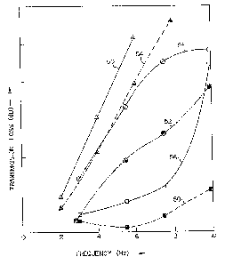
Example 1
A window 10 in accordance with Figure 2 was
prepared by forming septa 12, 14 from glass fabric
prepregged with 121°C cure epoxy in a thickness of
one quarter inch (0.630 cm) each. The core was
formed from natural rubber, 2-1/2 inches (6.35 em)
in thickness. The covering layers 18, 20 were
formed from BFGoodrich NOFOiIL rubber in a thickness
of 1-1/4 inches (3.1~ cm). Wlhen subjected to
acoustic transmission Clarity testing and acoustic
transmission loss testing, the structure formed in
this Example 1 yielded the performance curve set
forth as curve 50 in Figure 5. By contrast the
performance of 1-1/4 inch thick G RP (3.175 cm) is
plotted on curve 52 and 1/2 inch (1.27 cm) steel is
-19 -
plotted on curve 59. In Figure 5, the abcissa
plots frequency in Hz and the axis plots loss in
decibels. Performance was determined on 5 foot x 5
foot (7..52 m) panels at 21.6°C. The structure
produced in Example 1 was then duplicated, with the
septa again being formed of epoxy glass but 5/8
inches (1.27 cm) in thickness and the NOFOUL 1/2
inch (1.27 cm) in thickness. When subjected to
loss testing, the performance of this second
structure is characterized by the curve 56. For
comparison the performance of 2.1 inch thick G RP
(5.334 cm) is shown by curve 58 and the performance
of 5/6" steel .(1.59 cm) is shown by the curve 60.
Testing conditions and panel size remained
unchanged.
Windows in accordance with the invention
can be "tuned" by selection of septa 12, 14 and
core 16 thicknesses and materials to accommodate a
wide range of acoustical frequencies. This
selection naturally requires at the onset a certain
trial and error effort. acoustic waveforms of
frequency of at least about 500 hz but less than
about 50 khz can be accommodated with surprising
clarity and freedom from attenuation and
distortions while providing desirable structural
strength in the windows 10.
The laminate structure of the invention
having a core material possessed of lower static
and dynamic moduli than conventional window
construction materials, all as set forth herein,
permits a dynamic deaoupling of the laminate layers
12, 14, 16 in the presence of vibratians often
engendered by passage of the window through the
fluid in which it is employed or by transmitted
structural vibrations originating in the vessel
conveying the window. This decoupling tends to
-20-
reduce substantially the radiated noise
corresponding to this "in use" phase of the
window. Yet, absent these in use vibrations, the
window remains "hard", that is dynamically
decoupled and thereby structurally "stiff". This
decoupling is particularly effective in the range
of frequencies of about 1 khz to about 20 khz.
While a preferred embodiment of the
invention has been shown and described in detail it
should be apparent that various modifications may
be made thereto without departing from the scope of
the claims that follows.
20
30