Language selection

Search

Patent 2017977 Summary

Third-party information liability

Some of the information on this Web page has been provided by external sources. The Government of Canada is not responsible for the accuracy, reliability or currency of the information supplied by external sources. Users wishing to rely upon this information should consult directly with the source of the information. Content provided by external sources is not subject to official languages, privacy and accessibility requirements.

Claims and Abstract availability

Any discrepancies in the text and image of the Claims and Abstract are due to differing posting times. Text of the Claims and Abstract are posted:

  • At the time the application is open to public inspection;
  • At the time of issue of the patent (grant).
(12) Patent Application: (11) CA 2017977
(54) English Title: FIREPROOF MOUNTING ASSEMBLY FOR GLASS PANE
(54) French Title: ENSEMBLE DE MONTAGE IGNIFUGE POUR PANNEAU VITRE
Status: Deemed Abandoned and Beyond the Period of Reinstatement - Pending Response to Notice of Disregarded Communication
Bibliographic Data
(51) International Patent Classification (IPC):
  • E06B 3/00 (2006.01)
  • E06B 5/16 (2006.01)
(72) Inventors :
  • NOLTE, HANS-HENNING (Germany)
  • NOLTE, HANS-HENNIG (Germany)
(73) Owners :
  • FLACHGLAS AKTIENGESELLSCHAFT
(71) Applicants :
  • FLACHGLAS AKTIENGESELLSCHAFT (Germany)
(74) Agent: BORDEN LADNER GERVAIS LLP
(74) Associate agent:
(45) Issued:
(22) Filed Date: 1990-06-01
(41) Open to Public Inspection: 1990-12-03
Availability of licence: N/A
Dedicated to the Public: N/A
(25) Language of filing: English

Patent Cooperation Treaty (PCT): No

(30) Application Priority Data:
Application No. Country/Territory Date
P 39 18 158.8-25 (Germany) 1989-06-03

Abstracts

English Abstract


ABSTRACT
A glass pane has a pair of opposite faces and an outer edge and is held by
an adapter in a structural channel forming a groove. The adapter is formed in
part by respective metallic edge strips each having an inner portion overlying
a respective face of the pane and an outer portion projecting outward therefrom
and into the groove. The outer edge of the pane is spaced from the channel
and lies wholly outside the groove. Inner portions of the strips are secured
to the respective faces of the pane and a nonmetallic bar is secured between
the outer portions of the edge strips and engaged in the groove. The strips
are secured to the glass by an adhesive and each strip includes a perforate
under strip adhered to the glass and an imperforate cover strip adhered atop
the under strip. The adhesive has a silicone or water-glass base and is quite
resistant to heat.
PAT 15707-1


Claims

Note: Claims are shown in the official language in which they were submitted.

THE EMBODIMENTS OF THE INVENTION IN WHICH AN EXCLUSIVE PROPERTY OR PRIVILEGE
IS CLAIMED ARE DEFINED AS FOLLOWS:
1. An assembly comprising:
a glass pane having a pair of opposite faces and an outer edge;
a structural channel forming a groove; and
an adapter comprising
respective metallic edge strips each having an inner portion
overlying a respective face of the pane and an outer portion
projecting outwardly therepast and into the groove, the outer edge of
the pane being spaced from the channel and lying wholly outside the
groove,
an adhesive securing the inner portions to the respective faces
of the pane, and
a nonmetallic bar secured between the outer portions of the edge
strips and engaged in the groove.
2. The assembly defined in claim 1 wherein the strips each include a
perforate under strip secured to the respective glass face by the adhesive and
an imperforate cover strip adhered over the under strip.
3. The assembly defined in claim 1 wherein the outer edge is spaced
inwardly from the groove.
4. The assembly defined in claim 3 wherein the bar has an inner edge
lying outside the groove.
5. The assembly defined in claim 4 wherein the outer edge of the pane
and inner edge of the bar are spaced apart and separated by an air gap.
6. The assembly defined in claim 1, further comprising respective layers
of insulation lying between the outer portions of the strips and confronting
faces of the groove.
7. The assembly defined in claim 1 wherein the strips are of steel.
PAT 15707-1

8. The assembly defined in claim 1 wherein the strips are of expanded
metal.
9. The assembly defined in claim 1 wherein the strips have surfaces
turned toward the respective faces of the pane and provided with projections
holding them off the faces, the adhesive filling interstices between the
projections.
10. The assembly defined in claim 1 wherein the strips are of wire mesh.
11. The assembly defined in claim 1 wherein the strips are of metal and
less than 1mm thick.
12. The assembly defined in claim 1 wherein the glass pane is a
single-sheet safety glass, a borosilicate glass, or an aluminosilicate glass.
13. The assembly defined in claim 1 wherein the bar is of calcium
silicate.
PAT 15707-1

Description

Note: Descriptions are shown in the official language in which they were submitted.


2~ "17'~
FIREP~OOF MOUNTING ASSEMBLY FOR GLASS PANE
Field of the Invention
The present invention relates to mounting a glass pane. More
particularly, this invention concerns a fire-resistant mounting assembly ior
a glass pane.
Back~round oi the Invention
A pane of glass is normally mounted in firecode construction in a
fire-resistant irame, typically of metal. The outer edge of the glass pane
ls fitted into a channel of the frame. As described in German patent
2,328,737 filed 06 June 1973 by Ç. Ortm~nns and in German patent document
3,140,785 filed 14 October 1981 by G. Leyens et al., it is standard to
interpose a layer ~f heat-resistant insulation material in the channel on at
least one side of the pane, normally on the so-called cold side which is
that side on which fire is less likely. The insulaticn layer prevents the
glass pane irom pulling out of the frame.
Such an arrangement is only effective for relatively short-duration
fires. When, however, the pane is exposed to a fire for a much longer
period, for instance 60 mins., the glass pane deforms at its edges and comes
at least partially out of the channel holding its outer edge.
Objects oi_the Invention
It is therefore an object of the present invention to provide an
improved mounting assembly for a glass pane.
Another object is the provision of such an improved mounting assembly
for a glass pane which overcomes the above-given disadvantages, that is
which is capable of resisting considerable heat for a very long time.
SummarY of the Invention
A ~lass pane according to this invention has a pair of opposite faces
and an outer edge and is held in a structural channel forming a groove by an
adapter. The adapter is formed in part by respective metallic edge strips
each having an inner portion overlying a respective face of the pane and an
outer portion pro~ecting outwardly therepast and into the groove. The outer
PAT 15707-
~
- 1 -
''

'i;'7
edge of the pane is spaced from the channel and lies wholly outside the
groove. Inner portlons of the strips are secured adhesively to the
respective faces of the pane and a nonmetallic bar is secured between the
outer portions of the edge strips and engaged in the groove.
According to the invention each strip includes a pexforate under strlp
adhered to the glass and an imperforate cover strip adhered atop the under
strip. Preferably the adhesive has a silicone or water-glass base and is
quite resista~t to heat. Finely divided metallic particles having good
heat-conducting properties can be ~ixed with the adhesive. Multicomponent
glues needing no drying are preferr~d.
Thus, the glass is separated somewhat from the metallic frame so that
it will not be directly heated by it. It will be able to stand considerable
heat for quite some time before softening and separating from the frame.
There is therefore no significant temperature gradient between the
temperature of the glass pane and its edges. The adapter serves as a
temperature equalizer. It also has a ~echanical function to prevent
stresses caused by te~perature differentials from being effective to spring
the glass from its frame. The adapter itself solidly connects the pane to
the frame since on its inner side the adapter is fixed to the pane and on
its outer side it is solidly set in the frame.
In accordance with this invention the outer edge of the pane is spaced
inwardly from the groove and the bar has an inner edge lying outside the
groove. The outer edge of the pane and inner ed~e of the bar are spaced
apart and separated by an air gap and respective layers of insulation lie
between the outer portions of the strips and confronting faces of the
groove. The air gap is of a size about equal to about half the thickness of
the glass pane.
The under strips at least are normally made of steel, preferably of
expanded metal. These strips have surfaces turned toward the respective
faces of the pane and provided with projections holding them off the faces
so that the adhesive fills interstices between the projections. The under
str;ps at least can be made of wire mesh also and the cover strips can be of
metal and less than lmm thick. Such a cover strip protects the underlying
strip from direct contact with flames, but is so thin that it conducts only
insignificant amounts of heat.
PAT 15707-1
- 2 -

<t7~7
The pane according to this invention is a single-sheet safety glass, a
borosilicate glass, or an aluminosilicate glass. The bar is of calcium
silicate.
Description of the Drawing
The abo~e and other ob~ects, features, and advantages will become more
readily apparent from the following, reference being made to the accompanying
drawing in which:
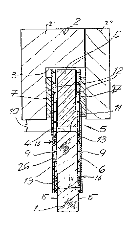
Fig. 1 is a cross section through an assembly according to this
invention; and
Fig. 2 is a partly cut-away side view of the assembly.
Specific Descript on
As seen in Figs. 1 and 2, a planar borosilicate or aluminosilicate
glass pane 1 has a pair of opposite faces 15 and an outer edge 4. A frame
or channel 2 formed of an L-shaped piece 2' and a bar 2" forms a groove 3
into whlch an adapter 5 secured to the outer periphery of the pane 1 fits.
The outer edge 4 of the pane is spaced inwardly from the frame by a spacing
1~ .
The adapter according to this invention consists of under strips 16
having inner portions 6 overlying the respective faces 15 of the pane 1 and
outer portions 7 projecting past the edge 4 into the groove 3. According to
this invention each under strip lh is formed of expanded metal or a wire
~esh and is protected by a decorative and imperforate cover strip 9. The
strips 16 on their surfaces facing the respecti~e faces of the pane 1 are
provided with pro~ections 26 holding them off the faces, and the adhesive
fills the interstices between the projections.
In the groove 3 between the inner portions 7 is a calcium-sillcate bar
8 and a heat-resis~ant and insulating compound layer 12 is provided between
the outer face of each inner portion 7 and the confronting flank of the
groove 3. The bar 8 is separated by an air gap 11 of a size equal to about
half of the thickness 14 of the glass pane 1 from the outer edge 4 of the
pane 1. A silicone- or water-glass-based glue 13 secures the inner portions
6 to the faces 15 of the pane 1 as well as to the cover strips 9 and to the
bar 8. m us the pane 1 is not only solidly held, but the joint is
PAT 15707-1
- 3 -

7'~
waterproof. Metallic heat-conducting particles can be mixed in the adhesive
13. The adapter 5 can be fitted to the pane 1 before it is itself fitted
into the frame 2.
PAT 15707-l
- 4 -

Representative Drawing
A single figure which represents the drawing illustrating the invention.
Administrative Status

2024-08-01:As part of the Next Generation Patents (NGP) transition, the Canadian Patents Database (CPD) now contains a more detailed Event History, which replicates the Event Log of our new back-office solution.

Please note that "Inactive:" events refers to events no longer in use in our new back-office solution.

For a clearer understanding of the status of the application/patent presented on this page, the site Disclaimer , as well as the definitions for Patent , Event History , Maintenance Fee  and Payment History  should be consulted.

Event History

Description Date
Inactive: IPC from MCD 2006-03-11
Time Limit for Reversal Expired 1994-12-01
Application Not Reinstated by Deadline 1994-12-01
Deemed Abandoned - Failure to Respond to Maintenance Fee Notice 1994-06-01
Inactive: Adhoc Request Documented 1994-06-01
Application Published (Open to Public Inspection) 1990-12-03

Abandonment History

Abandonment Date Reason Reinstatement Date
1994-06-01
Owners on Record

Note: Records showing the ownership history in alphabetical order.

Current Owners on Record
FLACHGLAS AKTIENGESELLSCHAFT
Past Owners on Record
HANS-HENNIG NOLTE
HANS-HENNING NOLTE
Past Owners that do not appear in the "Owners on Record" listing will appear in other documentation within the application.
Documents

To view selected files, please enter reCAPTCHA code :


To view images, click a link in the Document Description column. To download the documents, select one or more checkboxes in the first column and then click the "Download Selected in PDF format (Zip Archive)" or the "Download Selected as Single PDF" button.

List of published and non-published patent-specific documents on the CPD .

If you have any difficulty accessing content, you can call the Client Service Centre at 1-866-997-1936 or send them an e-mail at CIPO Client Service Centre.


Document
Description 
Date
(yyyy-mm-dd) 
Number of pages   Size of Image (KB) 
Cover Page 1990-12-03 1 17
Abstract 1990-12-03 1 20
Claims 1990-12-03 2 50
Drawings 1990-12-03 1 43
Descriptions 1990-12-03 4 142
Representative drawing 1999-07-29 1 20
Fees 1993-04-22 1 44
Fees 1992-05-07 1 53
PCT Correspondence 1992-11-19 1 22
PCT Correspondence 1992-01-20 1 27
Courtesy - Office Letter 1992-10-23 1 50