Language selection

Search

Patent 2018240 Summary

Third-party information liability

Some of the information on this Web page has been provided by external sources. The Government of Canada is not responsible for the accuracy, reliability or currency of the information supplied by external sources. Users wishing to rely upon this information should consult directly with the source of the information. Content provided by external sources is not subject to official languages, privacy and accessibility requirements.

Claims and Abstract availability

Any discrepancies in the text and image of the Claims and Abstract are due to differing posting times. Text of the Claims and Abstract are posted:

  • At the time the application is open to public inspection;
  • At the time of issue of the patent (grant).
(12) Patent Application: (11) CA 2018240
(54) English Title: FUEL INJECTION
(54) French Title: INJECTION DE CARBURANT
Status: Deemed Abandoned and Beyond the Period of Reinstatement - Pending Response to Notice of Disregarded Communication
Bibliographic Data
(51) International Patent Classification (IPC):
  • F02D 07/02 (2006.01)
  • F02M 51/00 (2006.01)
  • F02M 67/02 (2006.01)
(72) Inventors :
  • ALBERTSON, WILLIAM C. (United States of America)
(73) Owners :
  • GENERAL MOTORS CORPORATION
(71) Applicants :
  • GENERAL MOTORS CORPORATION (United States of America)
(74) Agent: GOWLING WLG (CANADA) LLP
(74) Associate agent:
(45) Issued:
(22) Filed Date: 1990-06-05
(41) Open to Public Inspection: 1990-12-21
Examination requested: 1990-06-05
Availability of licence: N/A
Dedicated to the Public: N/A
(25) Language of filing: English

Patent Cooperation Treaty (PCT): No

(30) Application Priority Data:
Application No. Country/Territory Date
07/369503 (United States of America) 1989-06-21

Abstracts

English Abstract


C-4162
PRESSURE REGULATOR
Abstract of the disclosure
A pressure regulator has a spool valve positioned by a linear
motor to control flow through a spill passage from a fuel inlet
to a fuel outlet and thereby control the fuel pressure in the
inlet as a function of the current in the linear motor, a piston
subjected to the pressure in the fuel inlet and defining a
variable orifice adapted to create a reference pressure at a
desired differential from the pressure in the fuel inlet, a
diaphragm subjected to the reference pressure and the pressure in
the air inlet, and a valve positioned by the diaphragm to control
flow from the air inlet to the air outlet whereby the pressure in
the air inlet is maintained at a desired differential below the
pressure in the fuel inlet.


Claims

Note: Claims are shown in the official language in which they were submitted.

Claim
1 - A pressure regulator comprising a body having a fuel inlet, a
fuel outlet, an air inlet, an air outlet, a spill passage
connecting the fuel inlet to the fuel outlet, a spool valve
controlling flow through the spill passage, a linear motor having
a coil and an armature, a stem connecting the armature to the
valve to position the valve to control flow through the spill
passage and thereby to control the fuel pressure in the inlet as
a function of the current in the coil, a piston subjected to the
pressure in the fuel inlet, the piston defining a variable
orifice adapted to create a reference pressure at a desired
differential from the pressure in the fuel inlet, a diaphragm
subjected to the reference pressure and the pressure in the air
inlet, and a valve positioned by the diaphragm to control flow
from the air inlet to the air outlet whereby the pressure in the
air inlet is maintained at a desired differential below the
pressure in the fuel inlet.

Description

Note: Descriptions are shown in the official language in which they were submitted.


G--2385 C-4162
FUEL INJECTION
5 Technical field
Thi~ invention provides a pressure regulator suitable ~or
controlling the pre~sures of fuel and air in a system for
injecting a charge of fuel and air directly into an engine
combustion chamber.
Summary of the drawing
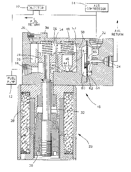
The sole figure of the drawing schematically illustrates an
lS injection system employing the pressure regulator provided by
this invention.
Detailed description
Referring to the drawing, an injector 10 receives fuel from a
fuel pump 12 and air from an air compressor 14 and directs a
fuel-air charge directly into an engine combustion chamber.
A pressure regulator 16 has an inlet 18 receiving fuel from fuel
pump 12 and an outlet 20 for discharging excess fuel through a
fuel return line. Pressure regulator 16 also has an inlet 22
receiving air ~rom air compressor 14 and an outlet 24 for
discharging exce6s air through an air return line. ~y
discharging excess fuel and air, pressure regulator 16 maintains
the fuel and air supplied to injector 10 at the desired
pressures.
Pressure regulator 16 includes a linear motor 26 having a coil 28
and an armature 30. Armature 30 carries a valve stem 32 that
positions a spool valve 34 at the entrance to a spill passage 36.
The position of spool valve 34 with respect to spill passage 36
controls fuel flow through spill passage 36 from inlet 18 to

outlet 20. A spring 38 biases spool valve 34 to obstruct fuel
flow through spill passage 36.
Spool valve 34 is moved upwardly as viewed in the drawing by the
uel pressure in inlet 18 until the force of spring 3~ balances
the inlet fuel pressure. The inlet fuel pressure ~ccordingly is
a function of spring force. When the coil 28 of linear motor 26
is energized, armature 30, valve stem 32 and spool valve 34 are
displaced upwardly as viewed in the drawing, thereby increasing
flow though spill passage 36 and reducing the inlet fuel
pressure. Linear motor accordingly has the effect of reducing
the force of spring 38 and correspondingly reducing the inlet
fuel pressure as a function of the current through coil 28.
To regulate the air pressure to injector 10 at a fixed
differential below the inlet fuel pressure, a sample of the inlet
fuel pressure is reduced to the desired air pressure and
communicated to an air pressure control. The space around the
reduced shank of spool valve 34 communicates the fuel pressure in
inlet 18 to a pressure chamber 40 closed by a piston 42. The end
44 of piston 42 has an orifice 46 and defines a valve surface
surrounding orifice 46. A spring 48 biases piston 42 toward the
wall 50 of pressure chamber 40. As fuel pressure increases in
inlet 18, piston 42 is displaced against the bias of spring 98,
thereby increasing the variable orifice defined between piston
valve ~urface 44 and the end 50 of pressure chamber. The chamber
52 behind piston 42 is connected by an orifice 54 to the chamber
56 behind spool valve 34 and thus to outlet 20.
Fixed orifice 46 and the variable orifice betweeen piston surface
44 and chamber wall 50, together with orifice 54, reduce the
pressure in chamber 52 to the desired differential below the
inlet fuel pressure. An aperture 58 communicates the pressure in
chamber 52 to a reference pressure chamber 60 closed by a
diaphragm 62.
The chamber 64 on the opposite side of diaphragm 62 is subjected

2~ o
to the pressure in air inlet 22. Diaphragm 62 carries a valve 66
that controls the discharge of excess air through outlet 24.
When the desired air pressure in reference chamber 52 is less
than the inlet air pressure in chamber 64, diaphragm 62 is
displaced le~twardly as viewed in the drawing; valve 66 is then
displaced from its seat 68 surrounding outlet 24 to increase air
flow through outlet 24 and thereby decrease the inlet air
pre~sure. When the desired air pressure in reference chamber 52
is greater than the inlet air pressure in chamber 64, diaphragm
62 is displaced rightwardly as viewed in the drawing; valve 66 is
then displaced toward seat 68 to decrease air flow through outlet
24 and thereby increase the inlet air pressure.

Representative Drawing
A single figure which represents the drawing illustrating the invention.
Administrative Status

2024-08-01:As part of the Next Generation Patents (NGP) transition, the Canadian Patents Database (CPD) now contains a more detailed Event History, which replicates the Event Log of our new back-office solution.

Please note that "Inactive:" events refers to events no longer in use in our new back-office solution.

For a clearer understanding of the status of the application/patent presented on this page, the site Disclaimer , as well as the definitions for Patent , Event History , Maintenance Fee  and Payment History  should be consulted.

Event History

Description Date
Inactive: IPC from MCD 2006-03-11
Application Not Reinstated by Deadline 1995-12-05
Time Limit for Reversal Expired 1995-12-05
Inactive: Adhoc Request Documented 1995-06-05
Deemed Abandoned - Failure to Respond to Maintenance Fee Notice 1995-06-05
Application Published (Open to Public Inspection) 1990-12-21
All Requirements for Examination Determined Compliant 1990-06-05
Request for Examination Requirements Determined Compliant 1990-06-05

Abandonment History

Abandonment Date Reason Reinstatement Date
1995-06-05
Owners on Record

Note: Records showing the ownership history in alphabetical order.

Current Owners on Record
GENERAL MOTORS CORPORATION
Past Owners on Record
WILLIAM C. ALBERTSON
Past Owners that do not appear in the "Owners on Record" listing will appear in other documentation within the application.
Documents

To view selected files, please enter reCAPTCHA code :


To view images, click a link in the Document Description column (Temporarily unavailable). To download the documents, select one or more checkboxes in the first column and then click the "Download Selected in PDF format (Zip Archive)" or the "Download Selected as Single PDF" button.

List of published and non-published patent-specific documents on the CPD .

If you have any difficulty accessing content, you can call the Client Service Centre at 1-866-997-1936 or send them an e-mail at CIPO Client Service Centre.

({010=All Documents, 020=As Filed, 030=As Open to Public Inspection, 040=At Issuance, 050=Examination, 060=Incoming Correspondence, 070=Miscellaneous, 080=Outgoing Correspondence, 090=Payment})


Document
Description 
Date
(yyyy-mm-dd) 
Number of pages   Size of Image (KB) 
Claims 1990-12-20 1 22
Abstract 1990-12-20 1 18
Drawings 1990-12-20 1 64
Descriptions 1990-12-20 3 91
Representative drawing 1999-07-28 1 58
Fees 1994-05-18 1 45
Fees 1993-05-20 1 29
Fees 1992-05-21 1 34
Courtesy - Office Letter 1990-11-14 1 20
Examiner Requisition 1993-03-31 1 54
Prosecution correspondence 1993-05-12 2 53