Language selection

Search

Patent 2018241 Summary

Third-party information liability

Some of the information on this Web page has been provided by external sources. The Government of Canada is not responsible for the accuracy, reliability or currency of the information supplied by external sources. Users wishing to rely upon this information should consult directly with the source of the information. Content provided by external sources is not subject to official languages, privacy and accessibility requirements.

Claims and Abstract availability

Any discrepancies in the text and image of the Claims and Abstract are due to differing posting times. Text of the Claims and Abstract are posted:

  • At the time the application is open to public inspection;
  • At the time of issue of the patent (grant).
(12) Patent Application: (11) CA 2018241
(54) English Title: FUEL INJECTION
(54) French Title: INJECTION DE CARBURANT
Status: Deemed Abandoned and Beyond the Period of Reinstatement - Pending Response to Notice of Disregarded Communication
Bibliographic Data
(51) International Patent Classification (IPC):
  • F02M 51/06 (2006.01)
  • F02B 75/02 (2006.01)
  • F02M 51/08 (2006.01)
  • F02M 61/04 (2006.01)
  • F02M 61/08 (2006.01)
  • F02M 67/12 (2006.01)
(72) Inventors :
  • WAHBA, BRENT J. (United States of America)
(73) Owners :
  • GENERAL MOTORS CORPORATION
(71) Applicants :
  • GENERAL MOTORS CORPORATION (United States of America)
(74) Agent: GOWLING WLG (CANADA) LLP
(74) Associate agent:
(45) Issued:
(22) Filed Date: 1990-06-05
(41) Open to Public Inspection: 1990-12-21
Examination requested: 1990-06-05
Availability of licence: N/A
Dedicated to the Public: N/A
(25) Language of filing: English

Patent Cooperation Treaty (PCT): No

(30) Application Priority Data:
Application No. Country/Territory Date
07/369502 (United States of America) 1989-06-21

Abstracts

English Abstract


C-4139
FUEL INJECTION
Abstract of the disclosure
In an injector adapted to deliver a charge of fuel and
air directly into the combustion chamber of a
two-stroke cycle engine, a pair of solenoid coils are
aligned along a common axis between an armature that
serves as a fuel metering valve and an armature that
operates a charge delivery valve.


Claims

Note: Claims are shown in the official language in which they were submitted.

Claim
1 - An injector for delivering a charge of fuel and air
directly into an engine combustion chamber, the
injector having an air inlet, a fuel inlet, a valve
seat surrounding the fuel inlet, a fuel metering
armature defining a fuel metering valve member, a fuel
metering valve spring biasing the fuel metering
armature to engage the fuel metering valve member with
the fuel inlet valve seat, a charge delivery valve seat
through which fuel and air are delivered to the engine,
a charge delivery valve member, an operating rod
extending from the charge delivery valve member, a
charge delivery valve spring biasing the operating rod
to engage the charge delivery valve member with the
charge delivery valve seat, a charge delivery armature,
a fuel metering solenoid coil, and a charge delivery
solenoid coil, the fuel metering armature being
effective when the fuel metering coil is energized to
displace the fuel metering valve member from the fuel
inlet valve seat while the charge delivery valve spring
maintains the charge delivery valve member in
engagement with the nozzle body valve seat, the charge
delivery armature being effective when the charge
delivery coil is energized to displace the operating
rod and thereby displace the charge delivery valve
member from the nozzle body valve seat, and wherein the
solenoid coils are aligned along a common axis and
disposed between the armatures.

Description

Note: Descriptions are shown in the official language in which they were submitted.


G-3081 C-4139
FUEL INJECTION
Technical field
This invention relates to an injector adapted to
deliver a charge of fuel and air directly into an
engine combustion chamber.
lt)
sackground
United States patent 4759335, issued 26 July 1988 in
the names of P. W. Ragg, M. L. McKay and R. S. srooks,
shows an injector that delivers a fuel-air charge
directly into the combustion chamber of a two-stroke
cycle engine. The injector has a valve that meters
fuel into the injector where the fuel mixes with air to
form a fuel-air charge, a valve that delivers the
2n fuel-air charge into the engine, and a pair of
solenoids that actuate the valves in sequence. The
solenoids are physically separate, creating a large
injector that requires substantial space on the engine.
Summary of the invention
This invention provides an in~ector having a pair o~
solenoids that are integrated in a single package to
minimize the size of the injector.
,
. ~' ,
"'
:

20~
In an injector employing this invention, a pair of
solenoid coils are aligned along a common axis between
one armature that serves as a fuel metering valve and
another armature that operates a charge delivery valve.
One coil is energized to open the fuel metering valve
and meter fuel into the injector where the fuel mixes
with air to form a fuel-air charge; the other coil is
energized to open the charge delivery valve and deliver
the fuel-air charge into the engine.
1~)
The details as well as other features and advantages of
an injector employing this invention are set forth in
the remainder of the specification and are shown in the
accompanying drawing.
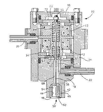
Summary_of the drawinq
The sole figure is a schematic axial sectional view of
an injector employing this invention, having a pair of
coils aligned along a common axis between a lower
armature that serves as a fuel metering valve and an
upper armature that operates a charge delivery valve.
The preferred embodiment
Referring to the drawing, an injector 10 has a pair of
solenoid coils 12 and 13 aligned along a common axis
; within a housing 14 between a cover 16 and a fuel body
18. An inlet fitting 20 directs air into housing 14,
and an inlet fitting 22 directs fuel into body 18. A
passage 30 opens from inlet fitting 22 through a valve
seat 32 into housing 14.
:

A locator ring 34 is sandwiched between coil 12 and
fuel body 18. Ring 34 positions a tapered armature
valve member 36 over valve seat 32. Armature valve
member 36 may have the attributes set forth in United
States patent 4572436 issued 25 February 1986 in the
names of E. R. Stettner, K. P. Cianfichi and D. D.
Stoltman.
Fuel body 18 has an extension 42 forming a nozzle
body. The nozzle body includes an insert 43 with a
central bore 44 surrounded by a valve seat 48.
A valve member 50 has a head 52 engaging valve seat 48
and a neck 54 extending into bore 44. An operating
rod 56 extends from valve member 50 through bore 44, a
mating bore 58 in fuel body 18, an opening 60 in
armature valve member 36, and a ~ore 62 through the
solenoid center pole 64, to a threaded end 66.
Another locator ring 70 is sandwiched between coil 12
and cover 16. An armature 72 is positioned by ring 70
about the threaded end 66 of rod 56 and is captured
between a nut 73 and a spring 68. Spring 68 i9
engaged between center pole 64 and armature 72 to bias
the head 52 of valve member 50 into engagement with
valve seat 48.
A spring 74 is engaged between center pole 64 and
armature valve member 36 to bias armature valve member
36 into engagement with valve seat 32.
~1~
: ~ '

2~
In operation, solenoid coil 12 is energized to lift
armature valve member 36 from seat 32 against the bias
of spring 74, while spring 68 holds valve member 50
against seat 48; armature valve member 36 then meters
fuel from passage 30 into housing 14 where it mixes
with the air to form a fuel-air charge. Then when
solenoid coil 13 is energized, armature 72 pushes rod
56 against the bias of spring 68 to displace valve
member 50 from seat 48, and valve member 50 allows the
fuel-air charge to pass through bores 58 and 44 and
delivers the fuel-air charge into the combustion
chamber of the engine (not shown).
Aligning coils 12 and 13 along a common axis, and
between armature valve member 36 and armature 72,
provides a compact cylindrical injector that may be
readily installed on the engine. Moreover, coils 12
and 13 share a portion o~ their flux paths, and a lead
through which current is supplied to the coils.

Representative Drawing
A single figure which represents the drawing illustrating the invention.
Administrative Status

2024-08-01:As part of the Next Generation Patents (NGP) transition, the Canadian Patents Database (CPD) now contains a more detailed Event History, which replicates the Event Log of our new back-office solution.

Please note that "Inactive:" events refers to events no longer in use in our new back-office solution.

For a clearer understanding of the status of the application/patent presented on this page, the site Disclaimer , as well as the definitions for Patent , Event History , Maintenance Fee  and Payment History  should be consulted.

Event History

Description Date
Inactive: IPC from MCD 2006-03-11
Time Limit for Reversal Expired 1994-12-05
Application Not Reinstated by Deadline 1994-12-05
Inactive: Adhoc Request Documented 1994-06-06
Deemed Abandoned - Failure to Respond to Maintenance Fee Notice 1994-06-06
Application Published (Open to Public Inspection) 1990-12-21
Request for Examination Requirements Determined Compliant 1990-06-05
All Requirements for Examination Determined Compliant 1990-06-05

Abandonment History

Abandonment Date Reason Reinstatement Date
1994-06-06
Owners on Record

Note: Records showing the ownership history in alphabetical order.

Current Owners on Record
GENERAL MOTORS CORPORATION
Past Owners on Record
BRENT J. WAHBA
Past Owners that do not appear in the "Owners on Record" listing will appear in other documentation within the application.
Documents

To view selected files, please enter reCAPTCHA code :


To view images, click a link in the Document Description column. To download the documents, select one or more checkboxes in the first column and then click the "Download Selected in PDF format (Zip Archive)" or the "Download Selected as Single PDF" button.

List of published and non-published patent-specific documents on the CPD .

If you have any difficulty accessing content, you can call the Client Service Centre at 1-866-997-1936 or send them an e-mail at CIPO Client Service Centre.


Document
Description 
Date
(yyyy-mm-dd) 
Number of pages   Size of Image (KB) 
Cover Page 1990-12-21 1 13
Abstract 1990-12-21 1 9
Claims 1990-12-21 1 32
Drawings 1990-12-21 1 50
Descriptions 1990-12-21 4 106
Representative drawing 1999-07-29 1 44
Fees 1993-05-21 1 32
Fees 1992-05-22 1 36
Examiner Requisition 1993-01-29 1 68
Courtesy - Office Letter 1990-11-15 1 20
Prosecution correspondence 1993-03-29 4 110