Note: Descriptions are shown in the official language in which they were submitted.
. 201R31~ ~
Speci-fication
Title o~ the Invention
Sel~-timer Device
Background o~ the Invention
The present invention relates to a sel~-timer
device used in cameras provided with a mechanical
shutter having an automatic ~ocusing ~unction.
Generally, in cameras having an automatic ~ocusing
(hereina~ter, abbreviated as "AF") ~unction, the stroke .
of a shutter button is arranged in two stages so that
when lt is depressed to a ~irst stage, an AF unit is ,.:
actuated, and a~ter the operation o~ the AF unit has
been completed (that is, a~ter ~ocusing has been ~ ;
complete), the depression to the second stage is
permltted to release a shutter.
With this arrangement, a ~ailure due to out o~
~ocus which is caused by a shutter released while the ~ :
AF unit is in operation can be prevented before it
happens. .~-.
This is also applicable when photographing is ~ .~
: :, :-. ., ~:
carried out using a sel~-timer, and the sel~ timer can
: . ;'
",:; .~..
'' `" ' .'.
'~ "' ':. ''
201t~31~
be usually actuated a~ter the operation o~ an AF unit ,;;
has been completed. ;
Nevertheless, in a case of cameras having a ;
mechanical shutter, the mechanisms o~ a shutter and a -. :
self-tlmer are indispensably complicated and made ~ :
larger in size in order to permit the sel~ timer to be
operated after the operation o~ an AF unit has been
completed as described above, which prevents the
cameras ~rom being made smaller in size as a whole and
the cost thereo~ ~rom being reduced.
That is, when the sel~ timer is used, an operator ~
cannot continuously depress a shutter button (in a :
state that the depression is e~ected to the first .
stage), and thus necessary is an arrangement to enable - ;
this state to be kept until a shutter is released a~ter : :
the ~ocusing has been completed.
Summary o~ the Invention
It is there~ore an ob~ect o~ the invention to
provide an improved shutter mechanism in which a -
shutter release button can be held at a first stage : .
during an auto-~ocusing operation be~ore the shutter is
actuated.
Another ob~ect o~ the invention is to provide an
2 : :
201R31$
improved self-timer device used in a cameras provided
with a mechanical shutter with an automatic focusing
~unction which can be simply arranged in a small size
and produced at a low cost.
According to one aspect o~ the invention, there is
provlded a shutter mechanism, adapted to be positioned
in a camera having a release member arranged to be
movable along a predetermined direction ~rom an
origlnal position there~or by depressing a shutter
10 button and a delay member relatively movable in ~ ;
parallel to said predetermined direction with said
release member, said delay member being biased along a
movlng direction o~ sald release member by a
predetermined biasing ~orce and being arranged to
actuate a shutter mechanism o~ said camera in case that ~ :
said delay member is located at a predetermlned ..
position, ~or locating said release member at another ;: .
predetermined position during a predetermined period
be~ore said delay member is located at said ::
2~ predetermined position, said shutter mechanism .~
comprising: : .
holding means ~or holding said delay member at a .
third predetermined position reversely designated to
said predetermined position along said moving direction . .
during said predetermined period; . :. ~
,'.'`'; . -'
3 ~
: ~ -.
20~3~
timer means for counting said predetermined
period;
releasing means ~or releasing the holding i
operation o~ sald holding means a-~ter said .
predetermined period; and .
controlling means ror controlling said release
member having been located at said another
predetermined position during said predetermined period
90 as to be located at said original position.
According to another aspect o~ the invention, -~
there is provided a sel~-timer device comprislng:
a release member arranged to be depressed by a
shutter button and biased in a direction opposite to .:~
the depressing direction;
a delay member relatively movable in parallel to
sald release member and biased to an opposite direction
o~ said depressing direction;
delay member stopping means ~or stoppin~ the
movement o~ said delay member at a predetermined
position~
a timer mechanism ~or counting a predetermined ~
period o~ time; :
locking means ~or locking said timer mechanism in
a set state, the locking operation being released by
the movement o~ said release member to a position
201~33~
corresponding to said predetermined position;
release member stopping means for stopping said
release member to prevent a returning operation thereof
~rom said predetermined posit;lon in a state that the
locking o~ said timer mechanism is released; and
releasing means ~or respectively releasing a
stopping operation o~ said delay member and said
release member arter said predetermined period counted
by sald timer mechanism becomes a predetermined value.
The release member and the delay member are moved
in combination at the initial stage Or the depression ~.:.
o~ the shutter button, the movement Or the delay member ::
:.
is restricted by the delay member restricting means ~ .
therearter, and ~urther the release member actuates the .~
locking means to release the locking thereor with the : ~:
timer mechanism, and the release member is restricted ;:;
by the release member restricting means to prevent the ;~
return thereo~, wherein at rirst when the restriction .
Or the delay member is released by the delay member
restriction releasing member moving in association with
.: . ,. ,:,
the timer mechanism, the delay member is moved ;~
~ollowing the release member by an urging ~orce to
actuate a shutter, and then the restriction Or the
release member is released by the release member ~:
: :.;.~ ~:.
restriction release means moving in association with .
,' "~'"'.'
, ' ;' ,
:' ' ' ~ '. ' '
2011~
:,
the timer mechanism to permi~ the same to return to an
lnitial state.
~ , .
Description o~ the AccomPanying Drawings
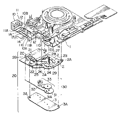
FIG. 1 is an exploded perspective view oE a
shutter button o~ a camera to which an embodiment of a
sel~-timer device according to the present invention is
applled and the portion of the self-timer device;
FIG. 2 is a plan view o~ an upper mother plate ln
a usual state o~ use;
FIG. 3 is a plan view o~ the upper mother plate
when a sel~-timer is set; and
FIG. 4 is a plan view of the mother plate when the
operation o~ the sel~ timer begins.
''~''' :'
Descri~tion o~ the Embodiments
FIG. 1 is a partial perspective view o~ a shutter
button o~ a camera to which an embodiment o~ a sel~-
timer device according to the present invention is
applied and the portion o-f the sel~-timer device.
The illustrated sel~-timer device comprises a
release rod 10 and a delay member 11 serving as a
release member which are upwardly and downwardly (along
;;~01~331~ ` :
a direction shown by an arrow AB in the drawing, a
direction indicated by "A" is upward direction and an
opposite direction indicated by "B" is downward
direction) slidingly disposed on the surface (upper
surface in the drawing) at one end o~ a shutter base :
plate 1 and a self-timer mechanism 20 disposed on the
back side o-~ the location where the release rod 10 and
the delay member 11 are disposed.
The release rod 10 is mounted on the shutter base
plate 1 in such a manner that the two slots de~ined at
the upper and lower portions thereof are slidingly
engaged with the guide pins 12, 12 disposed at the two ; :
locations at the upper and lower portions o~ the ~.
shutter base plate 1, and can be slidingly moved ~ .,
upwardly and downwardly by a predetermined stroke by
.., ..; . ,.
being guided by the guide pins 12, 12.
The delay member 11 is overlapped on the front
sur~ace of the release rod 10 with the slots de~ined
therethrough slidingly engaged with the guide pins 12, ~ ~.
;.:,.:~: ;::'.
20 12 slmilarly to the release rod 10. The delay member :;~ :
11 can also be slidingly moved by a predetermined stoke
independently o~ the release rod 10 in the dlrection :
along which the guide pins 12, 12 are disposed (upward
and downward directions). ,`
A spring locking proJection lOA is pro~ected from
.".',.':,~,',
~, . .
: ~
Z01~3~
.
the vicinity o~ the lower end o-~ the release rod 10
toward a side direction and springs 13 and 14 are
stretched between the spring locking pro~ection lOA,
and the locking hook lA pro~ected from the upper side
o~ the shutter base plate 1 and a locking portion llA
proJected ~rom the upper side o~ the delay member 11 :.
toward the side direction, respectively. And, the
release rod 10 ls urged upwardly o~ the shutter base
plate 1 by the stretch urging ~orce o~ the spring 13
10 and the delay member 11 is urged downwardly o~ the :
release rod 10 by the stretch urging ~orce o~ the
spring 14.
Note that, in a ~ree state, the lower edge sur~ace
o~ a stopper llB de~ined by being bent from the
predetermlned side edge o~ the delay member 11 toward
the back sur~ace ls held in abutment against the upper
slde edge sur~ace o~ the spring locking proJection lOA
o~ the release rod 10 to thereby determine the
posltional relationship therebetween, and in usual they
are slidlngly moved ln comblnatlon in this state and
~urther only the delay member can be prevented ~rom
being lowered ln such a manner that it is agalnst the
urging ~orce o~ the sprlng 14. In addition, as
described in detail later, the release rod 10 is
depressed by a not shown shutter button, which causes a , :-
201~31~
depressing portion llD o~ the delay member 11 moving in
association with the release rod 10 to depress a - :
shutter actuating member 4, whereby a shutter is
released.
An actuating proJection lOB ~or actuating the ~ :;
sel~-timer mechanisms 20 is proJected ~rom a
predetermined location on the back side of the release; ~;
rod 10 and the extreme end o~ the actuating pro~ection . .
reaches the inside o~ the self-timer mechanism 20 : ~`
disposed on the back side through the side edge cutout
o~ the shutter base plate 1. : :~
A leg llC having a predetermined width and bent a.~:.
predetermined length toward the back side is defined on
a side edge at the substantial center oi the delay
member 11 and the extreme end of the leg llC reaches
the lnside o~ the self-timer mechanism 20 dlsposed on
the back side through the side edge cutout o~ the
shutter base plate 1 similarly to the actuating
proJectlon o~ the release rod 10. .. ;'~
Further, the delay member 11 has the lower side
edge bent toward the back side in a predetermined width ..
.~ to ~orm the depressing portion llD ~or depressing the :~
shutter actuating member 4.
As described above, the sel~-timer mechanism 20
comprises an upper mother plate 2 and a lower mother .
''.' -
",.''. '.''
20~ 3~
plate 3 overlapped on the back side of the portion of
the shutter base plate 1 on which the release rod 10
and the delay member 11 are Mounted, a release rod
restricting member 21, a delay restricting member 22, a
sel~-timer actuating member 23, and a restriction
release member 24 are disposed on the upper sur~ace o~
the upper mother plate 2, i.e., the sur~ace confronting
the back sur~ace o~ the shutter base plate 1, and a
gear train and escape mechanism 30 with a timer
-~unction is interposed between the upper mother plate 2
and the lower mother plate 3.
The upper mother plate Z is mounted on the back
side o~ the shutter base plate 1 through bosses 2A
having a predetermined height disposed on predetermined
three positions on the upper sur~ace thereo~. A
predetermlned space is de~ined between the back sur~ace
o~ the shutter base plate 1 and the upper sur~ace oi~
the upper mother plate 2. Note that the extreme end
sur~ace o~ the actuating pro~ection of the release rod
10 is set at a position higher, i.e., apart, a
predetermined distance than the ~ront sur~ace o~ the
upper mother plate 2 to be described later and the
extreme end o~ the leg llC of the delay member 11 is
extended to a position where it ls inter~ered with the
upper mother plate 2. However, a slit 2B is defined to
,
.: ,~ . - :. . -: . - ; . .
i. ~ .. . . . .. .
z~
the portion o~ the upper mother plate 2 inter~ered with :~
the leg llC in the direction along which the delay :;:
member 11 is upwardly and downwardly moved, and thus
the extreme end o~ the leg llC is inserted into the ~ ::
slit 2B, whereby it is not interfered. ~.
Further, bosses having a predetermined height are ~:~
pro~ected from two diagonal positions on the lower
mother plate 3, the lower mother plate 3 is attached to :
the upper mother plate 2 through the bosses 3A, 3A,
10 and a space ln which the gear train and escape -:
mechanlsm 30 is contained is defined therebetween. ~ -~
As shown in FIG. 2 illustrating a plan view o~ the `:~ ::
upper mother plate 2, the release rod restricting : ~
member 21 is mounted on the upper mother plate 2 so :~ :
that it can be rotated by a sha~t 25, the delay
restricting member 22 is overlappingly mounted on the
upper side o~ the release rod restricting member 21 so ~ :
that it can be independently rotated by the same sha~t .
25, the restriction release member 24 is rotatively
mounted at the position corresponding to the extreme
end abutting portions 21A and 22A o~ the release rod .
restricting member 21 and the delay restricting member
22, and ~urther the sel~-timer actuating member 23 is
mounted with the extreme end locking claw 23A thereo~ ~
corresponding to the rotating area o~ the restriction . ,'
''''''''~'
".~,'' `'.',';~
2~ 31~L
release member 24 so that it can be rotated by a shaft
27.
The release rod restricting member 21 has one end
where the abuttlng portion 21A abutting against the
restriction release member 24 is defined and the other
end where the bent portion 21B is de~ined which is
interYered with the actuating prof ection o~ the release
rod restricting member 21 when the release rod
restricting member 21 is rotated a predetermined angle,
and one end o-~ a torsion spri.ng 28 wound around the
shaEt 27 by which the sel~-tlmer actuating member 23 is
supported is held in abutment against a pin 21C
disposed ln the vicinity of the abutting portion 21A,
whereby the release rod restricting member 21 is
rotated clockwise by the torsion spring 28.
The delay restricting member 22 has one end where
an abutting portion 22A similar to that o~ the release
rod restricting member 21 abutting against the
restricting release member 24 is dei~ined and the other
¦ 20 end where a i~ishhook-shaped stopper portion 22B is ~.
de~ined which is inter~ered with the moving area o~ the
¦ I leg llC of the delay member 11 to restrict the movement
¦ of the delay member 11 when the delay restricting
member 22 is rotated a predetermined angle, whereby the
delay restricting member 22 is rotated clockwise by a ~ ~:
12
.. ~ . - .. . . . . . .
:; .. . . . . . . . .
.,..... . : , . .:
. . .. . - ., ~ , . . . -
.. , . , ., ~ , . ,. , ~ : . :, . .
ZC3~L~31~
torsion spring 26 wound around the shaft 25. :
Note that the rotation of the release restricting
member 21 and the release restricting member 22 in a
rree state respectively caused by the urging ~orces o~
the torsion springs 26 and 28 are restricted in such a
manner that they are abutted against the boss 2A in the ; ;
vicinity o~ the abutting portions 21A and 22A,
respectively.
The restricting release member 24 is mounted on : .
the upper mother plate 2 so that it can be rotated by a
rotating shaYt 29, a locking portion 24A abutting
against the abutting portions 21A and 22A o~ the ;
release rod restrictlng member 21 and the delay
restricting member 22 and an engaging portion 24B
engaged with the extreme end locking claw 23A o~ the ;;;
sel~-timer actuating member 23 are de~ined at ~ ;
substantially symmetrical positions with respect to the :
rotating sha~t 29, and an engaging slit 24C is de~ined ~;
ln the vlclnity o~ the locking portion 24A. And, a
drive pin 31A, which is disposed at the predetermined
position o~ the first gear 31 o~ the gear train and
escape mechanism 30 to be described later in the ;~
vicinity o~ the circum~erence of the sur~ace thereo~ on ~
the upper mother plate 2 side, is engaged with the ;
engaging slit 24C passing through the upper mother :.
,',' '
13 ~. :
.,: .
: ,
2~
plate 2, whereby the restriction release member 24 and
the first gear 31 are rotated in synchronism. The hole
of the upper mother plate 2 through which the drive pin
31 passes is defined as an arc-shaped slot 2D having a
predetermined angle which does not prevent the rotation
Or the ~irst gear 31 and the restriction release member
24. In addition, the rotating shaft 29 is extended to
the front side and passes through the shutter base
p:Late 1, and thus the rotation of the rotating shaft 29
causes the restriction release member 24 and the first
gear 31 to be rotated to set a timer.
The self-timer actuating member 23 has a
substantially inverted "L"-shape, is rotatingly
supported by the shaft 27 in the vicinity of the bent
portion thereof, and has one end having the locking
claw 23A defined at the extreme end thereof which is
engaged with the engaging portion 24B of the
restrictlon release member 24 for restricting the
rotation thereof and the other end at which an
actuating portion 23B against which the actuatlng
pro~ection lOB of the release rod 10 is abutted is
bendingly defined. The end of the torsion spring 28
wound around the shaft 27 which is opposite to the end
thereof abutted against the pin 21C of the release rod
restricting member 21 is locked to the self-timer
. :.; - . .... . . , . ~ : , .- .~ :.
201~31~ `
actuating member 23 in the viclnity o~ the bent portion ~:
thereof so that it is rotated clockwise by the urging
force of the torsion spring 28 and the rotation thereof
is restricted by a not shown restricting member so that
the locking claw 23A is positioned at a predetermined . ;
position which is lnter~ered with the rotating area o~ :~
the engaging portion 24B. ~ ~
As described above, the gear train and escape ~:.
mechanism 30 constitutes a timer of the self-timer ~ ;
device, wherein a gear train 33 having a plurality of
gears is meshed with the first gear 31, one end of a . ;
sprlng 32 the other end of which ls locked to a hook 2C:~
deflned on the side edge o~ the upper mother plate 2 ~ -
i8 ~ixed to a predetermined positlon ln the vlclnity of
the outer clrcumference of the ~irst gear 31, and the;;.
flrst gear 31 is rotated clockwise by a stretch urging.,~
: :, i,:
~orce o~ the spring 32. When the ~irst gear 31 is
rotated counterclockwise by a predetermined angle '
against the stretch urging force o~ the spring 32 by
20 the operation o~ the shaft 29 and then the rotating :.
~orce is removed, the first gear 31 is rotated by the
stretch urging force of the spring 32, and thus the :.:
rotating force rotates the gear train 33 and a
predetermined ~riction is applied to the rotation so . :
that a predetermined period o~ time is necessary ~or ~
~ .
:: ' ,.;:
,, Z0~31~ '
the first gear 31 to return to the initial state.
The sel-f-timer device arranged as described above
operates as -~ollows.
In a usual photographing shown in FIG. 2, i.e., in
a state in which the self-timer is not used, the
rotating position of the ~irst gear 31 is located at an
inltial position by the stretch urging force of the
spring 32, and the restriction release member 24 having
the engaging slit 24C which ls engaged with the drlve
10 pin 31A disposed on the first gear 31 is located at the ~.
initial position by being restricted by the ~irst gear
31.
At the time, the locking portion 24A o~ the
restric~ion release member 24 is held in abutment of
the abutting portions 21A and 22A o~ the release rod
restricting member 21 and the delay restricting member
22 to restrict the release rod restricting member 21
and the delay restricting member 22 to the positions to
whlch they are rotated a predetermined angle
counterclockwise against the urging ~orces o~ the
torsion springs 26 and 28.
; In this state, the bent portion 21B of the
released rod restrlcting member 21 is out o~ the moving
area o~ the actuating pro~ection lOB of the release rod
10 and the stopper portion 22B of the delay restricting ,
16
:~ z~3~ ;
member 22 is also out Or the moving area of the leg llC
of the delay member 11, likewise. There~ore, the
downward movement o~ the actuating pro~ection lOB and
the leg llC o~ the delay member 11 is not regulated,
and thus the downward movement o-~ the release rod 10,
::,;. .;
i.e., the operation of the shutter actuating member 4
i.e., the shutter release operation can be achieved by
the depression of a not shown shutter button. Note
that at the beginning o~ the downward movement of the
release rod 10 caused by the depression of the shutter
button, an AF unit is actuated by a not shown
,; ,. ..
mechanlsm.
Next, the operation when the self-timer is
actuated will be described with reference to FIGs. 3
and 4.
FIG. 3 shows a state in which the sel~-timer is
set. More speci~ically, when the restriction release
member 24 is rotated by a not show actuating member a
predetermined angle counterclockwise irom the usual
photographing state shown in FIG. 2, i.e., the ~irst
gear 31 is rotated against the stretch urging ~orce o~
the spring 32, the engaging portion 24B o~ the
restriction release member 24 is engaged with the
extreme end locking claw 23A of the sel~-timer
actuating member 23, that is, the engaging portion 24B
17
: ZC~1~31~
o~ the restriction release member 24 causes the self- :
timer actuatlng member 23 to be rotated once
counterclockwise against the urging ~orce o~ the
torsion spring 28 and then is returned and engaged.
In thls state, the depressed abutment o~ the
abutting portions 21A and 2A of the release rod
restrlctlng member 21 and the delay restrlcting member
22 agalnst the locklng portion 24A of the restrlctlon
release member 24 ls released, and, as a result, the
release rod restrlctlng member 21 and the delay
restrictlng member 22 are made ~ree and rotated by the
urglng ~orces o~ the torslon springs 26 and 28,
respectively. At the time, the delay restrlctlng
member 22 is rotated until it is in contact wlth the
boss 2A and the stopper portlon 22B thereo~ ls
lnter~ered wlth the moving area o~ the leg llC o~ the
delay member 11 to cease the movement o~ the delay
member 11. In addition, the rotatlon o~ the release
rod restrlcting member 21 is ceased by the bent portion~ .
20 21 thereof which is held ln abutment against the side ~-
o~ the actuating pro~ection lOB o~ the release rod 10.
When the shutter button is depressed ln the state
shown ln FIG. 3, the release rod 10 and the delay
member 11 are lowered in comblnatlon at ~irst. The
actuatlng pro~ection lOB and the leg llC ln the state
18
, . ' ' ~,~.
z~1~3~
' : `.,
are respectively illustrated by one dot lines in FIG.
3. :
Here, since the stopper portion 22B o~ the delay ;. -.
restricting member 22 is interfered with the moving ;
area o~ the leg llC of the delay member 11, the leg llC ,i
ls held in abutment against the stopper portion 22B,
whereby the lowering o~ the delay member 11 is ceased. ;~
On the other hand, the release rod 10 depresses
:. :
the-self timer actuating member 23 through the
actuating pro~ection lOB thereo~ which is held in
abutment against the actuating portion o~ the sel~-
tlmer actuatlng member 23 and the sel~-timer actuating
member 23 is continuously lowered in such a manner that
it ls rotated counterclockwise against the urging force
o~ the torsion spring 28 about the shaft 27. :
,, ,
When the sel~-timer actuating member 23 is rotated ~ :
counterclockwlse by the actuatlng pro~ectlon lOB o~ the ~:
release rod 10, the engagement of the extreme end
locklng claw 23A thereo~ wlth the engagement portion o~ :;
the restrlctlon release member 24 ls released so that
the restriction release member 24 begins to be rotated --:
clockwlse by the stretch urging force of the spring 32,
that is, the timer begins operation.
At the same time, the actuating pro~ection lOB of
the release rod 10 moves from the bent portion 21B o~ ~:
19
.
2~ 31~L
the release rod restricting member 21 to the shaft 2~
side to permit the release rod restricting member 21 to
be rotated clockwise. As a result, the release rod
restricting member 21 is rotated by the urging force of
the torsion spring 28 to a position where it is held
abutment agalnst the boss 2A so that the bent portion
21B enters the upper moving area o~ the actuating
pro~ection lOB, as illustrated in FIG. 4.
When a finger o~ the operator is released from the
shutter button in this state, the release rod 10 tends
to be upwardly moved, i.e., returned, by the spring 13
stretched between the shutter base plate 1 and the
release rod 10, but this movement is prevented by the
actuatlng proJectlon lOB which ls held in abutment
agalnst the bent portion 21B o~ the release rod
restrlcting member 21, and thus the release member 10
is restrlcted ln a depressed state. That is, the ;~
operatlon o~ the AF unlt ls continuously held in the
state ln whlch the shutter button ls depressed.
When the ~lrst gear 31 of the gear train and
escape mechanism 30, l.e., the restricting release
member 24, 1s returned to the vicinity of the initial ~;
positlon ln a predetermlned perlod of tlme, the locklng
portlon 24A o~ the restriction release member 24 is ;
held in abutment against the abutting portions 21A and
.:,~','.. ~,
~ ~
' ' ', ~ ''.:'''
21~33~ ;
22A of the release rod restricting member 21 and the
delay restricting member 22, and the further rotation
of the first gear 31 causes the release rod restricting
member 21 and the delay restricting member 22 to be
rotated counterclockwise against the urging forces of
the torslon springs 26 and 28, respectively.
As a result, first, the stopper portion 22B of the
delay restricting member 22 retracts from the moving
area of the leg llC of the delay member 11, at the
moment the delay member 11 is lowered by the urging
force of the spring 14 stretched between the delay
member 11 and the release rod 10, and the depressing
portlon llD thereof depresses the shutter actuating
member 4, whereby the shutter is released.
More specifically, the shutter is released while
the AF unlt ls in operatlon when the shutter button is
depressed, whereby photographing by the self timer is
carried out.
As described above, according to the present
lnvention, a self-timer device used in cameras provided
with a mechanical shutter having an automatic focusing
function can be simply arranged in small size and thus
the cameras can be made small in size and the
manufacturing cost thereof can be reduced. ;
21