Language selection

Search

Patent 2018333 Summary

Third-party information liability

Some of the information on this Web page has been provided by external sources. The Government of Canada is not responsible for the accuracy, reliability or currency of the information supplied by external sources. Users wishing to rely upon this information should consult directly with the source of the information. Content provided by external sources is not subject to official languages, privacy and accessibility requirements.

Claims and Abstract availability

Any discrepancies in the text and image of the Claims and Abstract are due to differing posting times. Text of the Claims and Abstract are posted:

  • At the time the application is open to public inspection;
  • At the time of issue of the patent (grant).
(12) Patent: (11) CA 2018333
(54) English Title: TWISTING APPARATUS
(54) French Title: APPAREIL DE TORSION
Status: Expired and beyond the Period of Reversal
Bibliographic Data
(51) International Patent Classification (IPC):
  • B21D 11/06 (2006.01)
  • B21D 11/14 (2006.01)
(72) Inventors :
  • KEMP, ERNEST (United Kingdom)
(73) Owners :
  • CHESHUNT ENGINEERING LIMITED
(71) Applicants :
  • CHESHUNT ENGINEERING LIMITED (United Kingdom)
(74) Agent: GEORGE A. ROLSTONROLSTON, GEORGE A.
(74) Associate agent:
(45) Issued: 1995-02-14
(22) Filed Date: 1990-06-05
(41) Open to Public Inspection: 1990-12-08
Examination requested: 1994-03-30
Availability of licence: N/A
Dedicated to the Public: N/A
(25) Language of filing: English

Patent Cooperation Treaty (PCT): No

(30) Application Priority Data:
Application No. Country/Territory Date
89 13197.3 (United Kingdom) 1989-06-08

Abstracts

English Abstract


Apparatus for twisting a strip of flat material into a helix
or other suitable shape comprising one or more feed rollers
adapted to feed the strip in to means for guiding and
locating the strip in the plane of its longitudinal axis,
and from whence the strip passes into twist rolls which are
angularly rotatable with respect to the guide means and
which are provided with surfaces which grip the strip and
when so angularly rotated twist the strip about its
longitudinal axis.


Claims

Note: Claims are shown in the official language in which they were submitted.

THE EMBODIMENTS OF THE INVENTION IN WHICH AN EXCLUSIVE
PROPERTY OR PRIVILEGE IS CLAIMED ARE DEFINED AS FOLLOWS:-
1. Apparatus for twisting a strip of flat material into a
helix or other suitable shape comprising one or more feed
rollers adapted to feed the strip into means for guiding and
locating the strip in the plane of its longitudinal axis, and
from whence the strip passes into twist rolls which are
angularly rotatable with respect to the guide means and which
are provided with surfaces which grip the strip and when so
angularly rotated twist the strip about its longitudinal axis,
the twist rolls are non-driven and the feed rollers feed the
strip through the whole of the apparatus, the means for
guiding and locating the strip comprise guide wheels, the
guide wheels comprise two wheels on parallel spaced apart axes
and which have flanged edges, and the arrangement being such
that the strip is rigidly located and guided between the guide
wheels, and their flanged edges.
2. Apparatus as claimed in claim 1, in which the twist
rolls are in close proximity to the guide wheels.
3. Apparatus as claimed in claim 1, in which the guide
wheels and twist rolls are located in a housing which is
formed in two parts, the guide wheels being located in a part
which is fixed while the twist rolls are located in a part
which is angularly rotatable with respect to the fixed part.
4. Apparatus as claimed in claim 1, in which the twist
rolls comprise two twist wheels on parallel spaced apart axes
and each of which has a flange on one side which in
combination with a chamfered portion engages the faces of the
strip, the flange and chamfered portion on one twist wheel
being opposite to that on the other twist wheel.

5. Apparatus as claimed in claim 4, in which the guide
wheels and twist wheels are located in a housing which is
formed in two parts, the guide wheels being located in a part
which is fixed while the twist-wheels are located in a part
which is angularly rotatable with respect to the fixed part.
6. Apparatus as claimed in claim 4, in which each twist
wheel is also provided with a cylindrical portion which is
engaged by or closely abuts the flanges on the other twist
wheel.
7. Apparatus as claimed in claim 6, in which the guide
wheels and twist wheels are located in a housing which is
formed in two parts, the guide wheels being located in a part
which is fixed while the twist wheels are located in a part
which is angularly rotatable with respect to the fixed part.
8. Apparatus as claimed in claim 6, in which the strip is
engaged at its faces or sides by the cylindrical portion of
the twist wheel.
9. Apparatus as claimed in claim 8, in which the guide
wheels and twist wheels are located in a housing which is
formed in two parts, the guide wheels being located in a part
which is fixed while the twist wheels are located in a part
which is angularly rotatable with respect to the fixed part.
10. Apparatus for twisting a strip of flat material into a
helix or other suitable shape comprising one or more feed
rollers adapted to feed the strip into means for guiding and
locating the strip in the plane of its longitudinal axis, and
from whence the strip passes into twist rolls which are
angularly rotatable with respect to the guide means and which

are provided with surfaces which grip the strip and when so
angularly rotated twist the strip about its longitudinal axis,
the twist rolls are non-driven and the feed rollers feed the
strip through the whole of the apparatus, the means for
guiding and locating the strip comprise guide wheels said
guide wheels and twist rolls are located in a housing which is
formed in two parts, the guide wheels being located in a part
which is fixed while the twist rolls are located in a part
which is angularly rotatable with respect to the fixed part.

Description

Note: Descriptions are shown in the official language in which they were submitted.


- 1 - 20~8333
-
This invention relates to apparatus for twisting a strip of
flat material into a helix or other suitable shape.
According to the present invention such apparatus comprises
one or more feed rollers adapted to feed the strip into
means for guiding and locating the strip in the plane of its
longitudinal axis, and from whence the strip passes into
twist rolls which are angularly rotatable with respect to
the guide means and which are provided with surfaces which
grip the strip and when so angularly rotated twist the strip
about its longitudinal axis.
The twist rolls are preferably non-driven and the feed
rollers feed the strip through the whole of the apparatus.
The means for guiding and locating the strip comprise guide
wheels. These are preferably provided by two wheels on
parallel spaced apart axes and which have flanged edges the
arrangement being such that the strip is rigidly located and
guided between the rolls, and their flanged edges.
The twist rolls are preferably in close proximity to the
wheels and comprise in turn two wheels on parallel spaced
apart axes in each of which has a flange on one side which
in combination with a chamfered portion engages the faces of
the strip, the flange and chamfered portion on one wheel
being opposite to that on the other wheel. Each wheel is
also preferably provided with a cylindrical portion which is
engaged by or closely abuts the flanges on the other wheel.
The strip may be engaged at its faces or sides by the
cylindrical portions.
The guide wheels and twist wheels are preferably located in
a housing which is formed in two parts, the guide wheels
being located in a part which is fixed while the twist rolls
are located in a part which is angularly rotatable with
.~

- 2 _ 2 0 1 8 3 3 3
respect to the fixed part. The degree of rotation
preferably determines the pitch of the twist.
In a broad aspect, then, the present invention relates to an
apparatus for twisting a strip of flat material into a helix
or other suitable shape comprising one or more feed rollers
adapted to feed the strip into means for guiding and
locating the strip in the plane of its longitudinal axis,
and from whence the strip passes into twist rolls which are
angularly rotatable with respect to the guide means and
which are provided with surfaces which grip the strip and
when so angularly rotated twist the strip about its
longitudinal axis, the twist rolls are non-driven and the
feed rollers feed the strip through the whole of the
apparatus, the means for guiding and locating the strip
comprise guide wheels, the guide wheels comprise two wheels
on parallel spaced apart axes and which have flanged edges,
and the arrangement being such that the strip is rigidly
located and guided between the guide wheels, and their
flanged edges.
In another broad aspect, the present invention relates to an
apparatus for twisting a strip of flat material into a helix
or other suitable shape comprising one or more feed rollers
adapted to feed the strip into means for guiding and
locating the strip in the plane of its longitudinal axis,
and from whence the strip passes into twist rolls which are
angularly rotatable with respect to the guide means and
which are provided with surfaces which grip the strip and
when so angularly rotated twist the strip about its
longitudinal axis, the twist rolls are non-driven and the
feed rollers feed the strip through the whole of the
apparatus, the means for guiding and locating the strip
comprise guide wheels said guide wheels and twist rolls are
located in a housing which is formed in two parts, the guide
wheels being located in a part which is fixed while the

- 2a - 201 8333
twist rolls are located in a part which is angularly
rotatable with respect to the fixed part.
The invention may be performed in various ways and one
specific embodiment will now be described by way of example
with reference to the accompanying drawings in which:
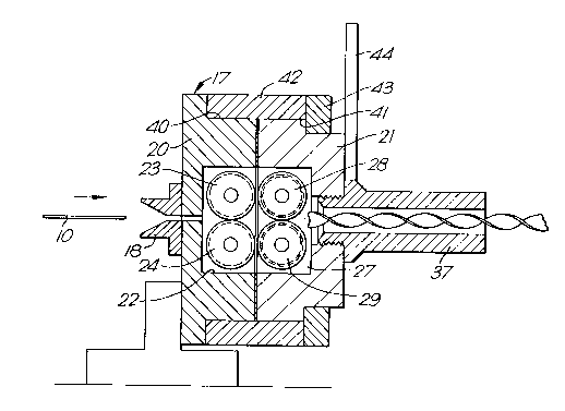
Figure 1 - is a general view of apparatus according to the
present invention
Figure 2 - is a cross section through the apparatus of
Figure 1
Figure 3 - is a side view of the entry guide wheels shown
in Figure 2
Figure 4 - is a side view of the rolls shown in Figure 2
and which are adapted to twist the material and
Figure 5 - is a view of the strip prior to twisting.
As shown in Figure 1 a strip, such as that shown in Figure 5
is received from a coil (not shown) and is fed through pinch
wheels 11, 12, 13, 14 and 15. These are shown somewhat
diagrammatically but the arrangement is such that they are
synchronously driven and engage the sides 16 of the strip 10
and drive it through the whole of the apparatus as described
hereafter.
From the pinch wheels the strip is fed into a helix
generator 17 through an entry guide slot 18. The helix
generator 17 is formed as a two part housing, the parts 20
and 21 of which are rotatable with respect to another as
more fully described hereafter.
The strip 10 passes through entry guide 18 in part 20 into a
circular cross section chamber 22 and in which are located

20~8333
-- 3 --
-
free wheeling guide wheels 23 and 24 having flanged edges 25
and 26 as shown more clearly in Figure 3 and which serve to
locate and guide the strip.
From guide wheels 23 and 24 the strip then passes into a
chamber 27 corresponding to chamber 22 in part 21 in which
are located wheels 28 and 29, also freewheeling, adapted to
twist the strip into a helical shape. The wheels 28 and 29
are shown more clearly in Figure 4 and have an outer flange
31 on wheel 28 and stepped down from which is a chamfered
portion 32, and stepped down from which is a cylindrical
portion 33. On wheel 29 is located, but in the opposite
sense, corresponding flange 34, stepped down chamfered
portion 35 and cylindrical portion 36. The strip 10 will be
located as shown during twisting.
_, ,,
An exit guide 37 is provided through which the strip passes
after leaving wheels 28 and 29.
As mentioned above part 21 is angularly rotatable with
respect to part 20. To this end the parts 20 and 21 are
provided with annular recesses 40, 41 respectively in their
outer circumference in which is located a collar 42 held
rigid with part 20 by suitable means such as bolts which
also pass through retaining ring 43 which in turn holds part
21 in position. The part 21 has an operating handle 44 by
means of which it can be rotated with respect to part 20.
In operation in order to start up the apparatus the strip 10
is fed from the coil through pinch wheels 11, 12, 13, 14 and
15 guide 18, guide rolls 23 and 24, and wheels 28 and 29,
which during the starting up operation are in the position
shown in Figure 2 that is parallel to rolls 23 and 24. In
this position the strip will pass into the exit guide 37
unchanged.
In order to obtain a twist in the strip part 21 is rotated

- 4 - 2018333
-
angularly by means of operating handle 44 with respect to
part 20. The degree of rotation determines the pitch of the
helix produced and the way in which the apparatus operates
is shown more clearly in Figure 4. In this the opposite
sides of the strip are caused to bear against the chamfers
32 and 35 whilst the sides of the strip are constrained by
the flanges 31 and 34 and cylindrical portions 33 and 36.
The wheels 28 and 29 when so formed provide a simple and
effective method of obtaining a twisted strip from a flat
strip. They are particularly suitable for materials such as
stainless steel which are not readily deformable.

Representative Drawing
A single figure which represents the drawing illustrating the invention.
Administrative Status

2024-08-01:As part of the Next Generation Patents (NGP) transition, the Canadian Patents Database (CPD) now contains a more detailed Event History, which replicates the Event Log of our new back-office solution.

Please note that "Inactive:" events refers to events no longer in use in our new back-office solution.

For a clearer understanding of the status of the application/patent presented on this page, the site Disclaimer , as well as the definitions for Patent , Event History , Maintenance Fee  and Payment History  should be consulted.

Event History

Description Date
Inactive: IPC from MCD 2006-03-11
Time Limit for Reversal Expired 2003-06-05
Letter Sent 2002-06-05
Inactive: Office letter 2000-05-18
Letter Sent 2000-04-14
Revocation of Agent Requirements Determined Compliant 1999-03-09
Appointment of Agent Requirements Determined Compliant 1999-03-09
Inactive: Office letter 1999-03-09
Inactive: Late MF processed 1999-02-12
Letter Sent 1998-06-05
Grant by Issuance 1995-02-14
All Requirements for Examination Determined Compliant 1994-03-30
Request for Examination Requirements Determined Compliant 1994-03-30
Application Published (Open to Public Inspection) 1990-12-08

Abandonment History

There is no abandonment history.

Fee History

Fee Type Anniversary Year Due Date Paid Date
MF (patent, 7th anniv.) - small 1997-06-05 1997-05-30
MF (patent, 8th anniv.) - small 1998-06-05 1999-02-12
MF (patent, 9th anniv.) - small 1999-06-07 1999-02-12
Reversal of deemed expiry 1998-06-05 1999-02-12
Registration of a document 2000-03-21
MF (patent, 10th anniv.) - small 2000-06-05 2000-05-04
MF (patent, 11th anniv.) - small 2001-06-05 2001-05-04
Owners on Record

Note: Records showing the ownership history in alphabetical order.

Current Owners on Record
CHESHUNT ENGINEERING LIMITED
Past Owners on Record
ERNEST KEMP
Past Owners that do not appear in the "Owners on Record" listing will appear in other documentation within the application.
Documents

To view selected files, please enter reCAPTCHA code :


To view images, click a link in the Document Description column. To download the documents, select one or more checkboxes in the first column and then click the "Download Selected in PDF format (Zip Archive)" or the "Download Selected as Single PDF" button.

List of published and non-published patent-specific documents on the CPD .

If you have any difficulty accessing content, you can call the Client Service Centre at 1-866-997-1936 or send them an e-mail at CIPO Client Service Centre.


Document
Description 
Date
(yyyy-mm-dd) 
Number of pages   Size of Image (KB) 
Abstract 1995-02-13 1 14
Drawings 1995-02-13 2 39
Description 1995-02-13 5 190
Abstract 1995-02-13 1 14
Claims 1995-02-13 3 104
Representative drawing 1999-07-28 1 19
Maintenance Fee Notice 1998-07-05 1 179
Late Payment Acknowledgement 1999-03-02 1 172
Courtesy - Certificate of registration (related document(s)) 2000-04-13 1 113
Maintenance Fee Notice 2002-07-02 1 177
Fees 1999-02-11 2 46
Correspondence 2000-05-17 2 11
Fees 1997-05-29 1 39
Fees 2000-05-25 1 31
Fees 2001-05-03 1 28
Correspondence 1999-03-08 1 5
Fees 2000-05-03 1 32
Fees 1996-06-04 1 40
Fees 1995-05-29 1 41
Fees 1994-06-05 1 39
Fees 1993-06-03 1 31
Fees 1992-04-30 1 29
Courtesy - Office Letter 1999-03-08 2 45
Prosecution correspondence 1990-08-23 1 34
PCT Correspondence 1990-08-23 1 29
Courtesy - Office Letter 1991-04-19 1 16
Prosecution correspondence 1990-08-23 1 26
PCT Correspondence 1990-11-09 2 49
Prosecution correspondence 1994-03-29 5 137
Examiner Requisition 1993-12-29 1 55
Courtesy - Office Letter 1991-04-24 1 20