Note: Descriptions are shown in the official language in which they were submitted.
2~
Mo3231
PC-225
BAR SUPPORT FOR CONCRETE
FIELD OF THE INVENTION
The present invention relates to reinforced concrete
technology and more particularly to means to support the
reinforcement.
BACKGROUND OF THE INVENTION
In the manufacture of reinforced concrete structures
steel rods are supported, in a horizontal orientation, by any of
a variety of means. Where the supports are made of metal there
is often formation of rust which is objectionable from the
mechanical and aesthetical view points. The art is noted to
include U.S. Patent 3,114,221 which disclosed a rod-supporting
chair which serves in supporting at a predetermined level above a
subgrade a series of reinforcing rods in connection with a
concrete paving installation.
It is an object of the present invention to provide a
supporting chair for steel reinforcing rods and the like,
sometimes referrèd to in the relevant art as a "re-bar chair",
which is useful in the preparation of reinforced concrete.
It is a further object of the invention to provide a
supporting chair for reinforcing rods which are commonly used in
the fabrication of reinforced concrete.
It is a further object of the invention to provide
support for horizontally oriented reinforcing rods used for
concrete applications.
Another principal object of the invention is to provide
a rod supporting chair which features a novel locking means for
retaining the reinforcing rod in position.
A yet another object of the invention is to provide a
supporting chair for reinforcing rods which is essentially of a
one-piece construction.
35052AP0426
~0~ ~38~ .
-2--
A still further object of the invention is to provide a
rod-supporting chair having associated therewith a rod-receiving
cradle which is an integral part of the chair.
This and other objects are met by the present invention
5 as describe below.
SUMMARY OF THE IWVENTION
The present invention is directed to a chair for
maintaining and supporting a cylindrical, horizontally extending,
reinforcing rod in a fixed position in conne~tion with a concrete
10 installation. The chair comprise a thermoplastically molded or
extruded channel having two integrally molded, preferably
vertical side walls -flanges- running along its long dimension,
each of which walls includes a cut section which permits bending
the channel across its long dimension to form a cradle of
15 reasonably tight fit around at least part of the circumferential
cross-section of a reinforcing rod. The chair further contains
means to secure its shape when in use.
DETAILED DESCRIPTION OF THE INVENTION
The rod-support re-bar chair of the present invention
20 is best described by reference to Figures 1, 2 and 3.
In Figure 1 there is shown the chair of the invention
in its pre-use un-bent configuration.
In Figure 2 there is shown a strap used for fastening
the legs of the chair upon use. .
In Figure 3 there is shown one of the rod supporting
chairs of the present invention operatively associated with a
reinforcing rod.
Referring to the drawings in detail and in particular
to Figure 1, the chair in its pre-use configuration comprises a
30 plastic channel 1, having two vertical side walls 3, running
along its long dimension preferably parallel one to the other.
In the center of each of said side walls there is cut from the
edge of the wall, a section having a semi-elliptical or a semi-
circular shape 2, which forms, when the channel is bent across
Mo3231
_3 ~ 3~1
its long dimension to form the chair of the invention, a
reasonably tight fit around at least part of the circumference of
the cross-section of the reinforcing rod. The cut, molded-in or
drilled hole 4, and the corresponding aperture 5, are provided
5 for the accommodation of the optional fastening strap 6, which is
shown in Figure 2. Further, in Figure 2 there is represented the
end 8, of the strap 6, which is, when in use, inserted through
hole 4, and aperture 5. The striations 7 are indicated to aid in
the locking the strap in place upon the use of the chair. The
10 tightening strap is but one possible means to secure the legs of
the chair in its "in-use", bent shape. Other means having the
same function of locking the legs of the chair are well known in
the art and are equally suitable in the context of the present
invention.
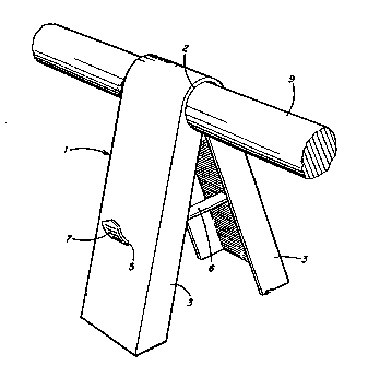
In Figure 3, there is represented the chair 1, in its
"in-use" configuration wrapped around the circumferential
cross-section of a reinforcing steel rod 9, and held in place by
a tightening strap 6.
Typically, the shape of the chair formed upon bending
20 the channel across its long dimension resembles the letter "A"
where the reinforcing rod is held in place - cradled- at the
joint formed between the legs of the "A". One advantageous rule
to follow in forming the channel of the invention is to ensure
that the legs of the chair once in use, form an angle of about
25 40 therebetween. Naturally, the optimum angle depends to a
large degree on the material used to form the channel, the
physical dimensions of the channel and the ultimate load it is
designed to support. Channels having a length of up to 36
inches, made of polycarbonate by extrusion, and a wall thickness
30 of about 1/8 inch designed to support a rod having a length of
about 20- feet, the preferred angle is about 40.
Mo3231
2~1~38~
-4-
The chair of the invention is molded, preferably
extruded, from a thermoplastic resin, preferably polycarbonate
resin by methods well known in the art. The basic requirement is
that the resin have adequate mechanical properties including in
5 particular stiffness. While not a strict requirement for the
successful use of the chair, it is preferred that the resin is
chemically resistant to the alkaline environment which prevails
in the interior of cement based products. Among the suitable
resins for the preparation of the chair of the invention, mention
10 may be made of polycarbonate, polyester-carbonate and aromatic
polyester. The chair is best molded as a channel as shown in
Figure 1. The width of the channel, its wall thickness and the
verticality of its side walls are not critical to the invention
and the only requirement is that in its "in-use" configuration,
15 the chair, as part of a set of chairs, be able to support the
weight of the reinforcing rod. Typically, the channel is about
one (1) to about one and a half (1 1/2) inches wide; the wall
thickness is typically in the order of 1/16 to about 3/16 inches,
preferably 1/8 inch. The cut out section 2, is positioned at the
20 center of the wall at its free edge and forms upon the bending of
the channel across its long dimension and around the
cross-section of a reinforcing rod, a cradle having a suitable
fit around at least part of the circumference of the rod. The
cut out section may be either molded into the channel in a
25 fashion well known in the art or cut into the channel in a
separate operation. Likewise the hole 4, and aperture 5, may be
formed by drilling or punching or they may be formed as an
integral feature of the channel during molding.
It is to be noted that the chair of the invention may
30 be manufactured in one operation using molding methods known in
the art. Because of this factor and because the chair is made of
primary one part and because it lends itself to easy assembly and
put to use in a most economical fashion, the chair offers an
attractive choice for reinforcing rods supports.
Mo3231
~183~1
The invention is not to be limited to the exact
arrangement and dimensions provided above for illustration
purposes only, as changes in the details of the construction or
of the fabrication of the chair are within the claims as stated
5 below.
Mo3231
,,: ~,. .
` ' . . ' ' ~