Language selection

Search

Patent 2018414 Summary

Third-party information liability

Some of the information on this Web page has been provided by external sources. The Government of Canada is not responsible for the accuracy, reliability or currency of the information supplied by external sources. Users wishing to rely upon this information should consult directly with the source of the information. Content provided by external sources is not subject to official languages, privacy and accessibility requirements.

Claims and Abstract availability

Any discrepancies in the text and image of the Claims and Abstract are due to differing posting times. Text of the Claims and Abstract are posted:

  • At the time the application is open to public inspection;
  • At the time of issue of the patent (grant).
(12) Patent: (11) CA 2018414
(54) English Title: METHOD AND MEANS OF CONVEYANCE OF SOLID MATTER IN PIECES OR PARTICLES
(54) French Title: METHODE ET MOYEN DE TRANSPORT DE MATIERE SOLIDE EN MORCEAUX OU EN PARTICULES
Status: Expired
Bibliographic Data
(52) Canadian Patent Classification (CPC):
  • 198/92
(51) International Patent Classification (IPC):
  • B65G 25/00 (2006.01)
  • B27L 1/00 (2006.01)
  • B27L 1/04 (2006.01)
  • B65G 25/06 (2006.01)
(72) Inventors :
  • JONKKA, ARVO (Finland)
(73) Owners :
  • RAUMA-REPOLA OY (Finland)
(71) Applicants :
  • RAUMA-REPOLA OY (Finland)
(74) Agent: OSLER, HOSKIN & HARCOURT LLP
(74) Associate agent:
(45) Issued: 2001-08-07
(22) Filed Date: 1990-06-06
(41) Open to Public Inspection: 1991-01-03
Examination requested: 1997-05-14
Availability of licence: N/A
(25) Language of filing: English

Patent Cooperation Treaty (PCT): No

(30) Application Priority Data:
Application No. Country/Territory Date
89 3230 Finland 1989-07-03
89 4387 Finland 1989-09-18
90 1423 Finland 1990-03-21

Abstracts

English Abstract


Method and means of conveyance for solid
material, f.ex. tree trunks (6) or bark, whereby
the solid material is conveyed with parallel,
oblong transfer elements (4) moving back and forth
in transfer direction. A larger part of the
surf ace of the transfer elements (4) is moving
forward at a time than moving backward. The speed
of the return motion of the transfer elements is
higher than that of the feed motion of the trans-
fer elements. Transfer elements (4) at sides of
the conveyor have been inclined on their longi-
tudinal axis so that they slope towards the centre
of the conveyor. In this way the friction force
between the particles (6) of the material to be
conveyed is increased and the friction force
between the maternal (6) to be conveyed and the
transfer elements (4) is decreased.


Claims

Note: Claims are shown in the official language in which they were submitted.


THE EMBODIMENTS OF THE INVENTION IN WHICH AN EXCLUSIVE
PROPERTY OR PRIVILEGE IS CLAIMED ARE DEFINED AS FOLLOWS:

1. A method of conveying pieces of material comprising
the steps of:
placing said pieces of material onto a support surface
area of a conveyor formed of a plurality of parallel oblong
transfer elements;
simultaneously moving a predetermined number of said
transfer elements in a forward motion and a predetermined
number of said transfer elements in a return motion along a
line parallel to a conveying direction such that said support
surface area of said conveyor includes a forward moving surface
area and a return moving surface area, wherein at any
predetermined period of time, said forward moving surface area
is in contact with said pieces of material and is larger than
said return moving surface area, and wherein the speed of said
return motion is higher than the speed of the forward motion;
urging said pieces of material through said conveyor
wherein a first frictional force between each of the pieces is
increased as a result of positioning outermost transfer
elements at an angle relative to a horizontal plane, said first
frictional force being greater than a second frictional force
existing between the pieces of material that are being conveyed
and the transfer elements.

2. A means for conveying pieces of material comprising:
frame means;
a plurality of oblong shaped transfer elements positioned
substantially parallel to each other along a conveying
direction on said frame means to form a conveyor with a
predetermined surface area, said transfer elements being
movable in a forward and return motion along a line parallel
to said conveying direction such that said conveyor has a
forward moving surface area and a return moving surface area
at any particular period of time; said forward moving surface
area being in contact with said pieces of material and being
larger than said return moving surface area at any particular


period of time;
means for moving each of said plurality of transfer
elements at a return speed of movement that is greater than a
forward speed of movement; and
outermost transfer elements of said conveyor being
inclined relative to a horizontal plane such that said
outermost transfer elements slope towards a center of said
conveyor.
3. A means for conveying pieces of material as set forth
in claim 2, wherein transfer elements on either side of a
center region of said conveyor are positioned at an angle of
inclination relative to said horizontal plane such that said
conveyor has a substantially semi-circular cross-section.
4. A means for conveying pieces of material as set forth
in claim 2, wherein said plurality of transfer elements are
positioned to receive a substantial portion of a primary
contact surface area of each of said pieces of material.
5. A means for conveying pieces of material as set forth
in claim 2, further comprising a drum means for debarking tree
trunks positioned adjacent said conveyor, said drum means
having a revolving feed opening, said feed opening having a
bottom form conforming to a bottom form of said transfer
elements of said conveyor, said transfer elements extending
across an end face of said drum means at said feed opening.
6. A means for conveying pieces of material as set forth
in claim 2, wherein said plurality of transfer elements include
transfer surfaces, said transfer surfaces being arranged
parallel to said conveying direction, said transfer surfaces
having a frictional surface for creating a feeding frictional
force by which said pieces of material are conveyed.
7. A means for conveying pieces of material as set forth
in claim 3, wherein said plurality of transfer elements are
positioned to receive a substantial portion of a primary
contact surface area of each of said pieces of material.
8. A means for conveying pieces of material as set forth
in claim 3, further comprising a drum means for debarking tree


trunks positioned adjacent said conveyor, said drum means
having a revolving feed opening, said feed opening having a
bottom form conforming to a bottom form of said transfer
elements of said conveyor, said transfer elements extending
across an end face of said drum means at said feed opening.
9. A means for conveying pieces of material as set forth
in claim 4, further comprising a drum means for debarking tree
trunks positioned adjacent said conveyor, said drum means
having a revolving feed opening, said feed opening having a
bottom form conforming to a bottom form of said transfer
elements of said conveyor, said transfer elements extending
across an end face of said drum means at said feed opening.
10. A means for conveying pieces of material as set forth
in claim 7, further comprising a drum means for debarking tree
trunks positioned adjacent said conveyor, said drum means
having a revolving feed opening, said feed opening having a
bottom form conforming to a bottom form of said transfer
elements of said conveyor, said transfer elements extending
across an end face of said drum means at said feed opening.
11. A means for conveying pieces of material as set forth
in claim 3, wherein said plurality of transfer elements include
transfer surfaces, said transfer surfaces being arranged
parallel to said conveying direction, said transfer surfaces
having a frictional surface for creating a feeding frictional
force by which said pieces of material are conveyed.
12. A means for conveying pieces of material as set forth
in claim 4, wherein said plurality of transfer elements include
transfer surfaces, said transfer surfaces being arranged
parallel to said conveying direction, said transfer surfaces
having a frictional surface for creating a feeding frictional
force by which said pieces of material are conveyed.
13. A means for conveying pieces of material as set forth
in claim 5, wherein said plurality of transfer elements include
transfer surfaces, said transfer surfaces being arranged
parallel to said conveying direction, said transfer surfaces
having a frictional surface for creating a feeding frictional


force by which said pieces of material are conveyed.
14. A means for conveying pieces of material as set forth
in claim 7, wherein said plurality of transfer elements include
transfer surfaces, said transfer surfaces being arranged
parallel to said conveying direction, said transfer surfaces
having a frictional surface for creating a feeding frictional
force by which said pieces of material are conveyed.
15. A means for conveying pieces of material as set forth
in claim 8, wherein said plurality of transfer elements include
transfer surfaces, said transfer surfaces being arranged
parallel to said conveying direction, said transfer surfaces
having a frictional surface for creating a feeding frictional
force by which said pieces of material are conveyed.
16. A means for conveying pieces of material as set forth
in claim 9, wherein said plurality of transfer elements include
transfer surfaces, said transfer surfaces being arranged
parallel to said conveying direction, said transfer surfaces
having a frictional surface for creating a feeding frictional
force by which said pieces of material are conveyed.
17. A means for conveying pieces of material as set forth
in claim 10, wherein said plurality of transfer elements
include transfer surfaces, said transfer surfaces being
arranged parallel to said conveying direction, said transfer
surfaces having a frictional surface for creating a feeding
frictional force by which said pieces of material are conveyed.

Description

Note: Descriptions are shown in the official language in which they were submitted.


r018~114
Method and means of conveyance of solid matter in pieces or
particles
This invention concerns a method for conveyance of solid
matter that is in pieces or particles, for excample tree
trunks or bark in a way that the solid matter is conveyed by
parallel, oblong transfer elements moving back and forth in
transfer direction, wherein a larger part of the surface of
transfer elements in connection with the material to be
conveyed is moving forward at a time than moving backward,
and the speed of the return motion of the transfer elements
is higher than that of the feed motion of the transfer ele-
ments. The invention also concerns a means of conveyance
for solid matter that is in pieces or particles, for excample
tree trunks or bark, consisting of parallel, oblong transfer
elements movable back and forth in transfer direction, where-
in a larger part of the surface of transfer elements in
connection with the material to be conveyed is moving forward
at a time than moving backward and the speed of the return
motion of the transfer elements is higher than that of the
feed motion of the transfer elements.
In front of barking drums generally used for debarking of
trees it is known to use a trough-formed feeding unit
equipped with a conveyor, where the trunks to be debarked are
led in. As 'the debarking length of trunks to be debarked has
increased it is becoming general to transport trunks length-
wise. As conveyor on the bottom of the trough it has been
used endless, parallel arranged chains that are furnished
with pushers projecting upwards. These pushers cling to the
stump end of trunks and push the trunks lengthwise towards
the open end of the barking drum. This kind of feeder unit
is described f.ex. in FI-patent application 86 4827. The
problem with these chain conveyors is the fact 'that each
link is loaded by big loads and the wearing of links of
flexible chains. For this reason the chains can easily '
break.


CA 02018414 1998-02-02
2
Also the so called "stoker feeder" is known, that is, a
back and forth moving feeder furnished with proj ecting pushers .
This kind of feeder moving back and forth has earlier been used
for unloading of bulk material, f.ex. chip from a silo.
In accordance with an embodiment of the present invention
there is provided a method of conveying pieces of material
comprising the steps of: placing the pieces of material onto
a support surface area of a conveyor formed of a plurality of
parallel oblong transfer elements; simultaneously moving a
predetermined number of the transfer elements in a forward
motion and a predetermined number of the transfer elements in
a return motion along a line parallel to a conveying direction
such that the support surface area of the conveyor includes a
forward moving surface area and a return moving surface area,
wherein at any predetermined period of time, the forward moving
surface area is in contact with the pieces of material and is
larger than the return moving surface area, and wherein the
speed of the return motion is higher than the speed of the
forward motion; urging the pieces of material through the
conveyor wherein a first frictional force between each of the
pieces is increased as a result of positioning outermost
transfer elements at an angle relative to a horizontal plane,
the first frictional force being greater than a second
frictional force existing between the pieces of material that
are being conveyed and the transfer elements.
In accordance with another embodiment of the present
invention there is provided a means for conveying pieces of
material comprising: frame means; a plurality of oblong shaped
transfer elements positioned substantially parallel to each
other along a conveying direction on the frame means to form
a conveyor with a predetermined surface area, the transfer
elements being movable in a forward and return motion along a
line parallel to the conveying direction such that the conveyor
has a forward moving surface area and a return moving surface
area at any particular period of time: the forward moving


CA 02018414 1998-02-02
2a
surface area being in contact with the pieces of material and
being larger than the return moving surface area at any
particular period of time: means for moving each of the
plurality of transfer elements at a return speed of movement
that is greater than a forward speed of movement; and outermost
transfer elements of the conveyor being inclined relative to
a horizontal plane such that the outermost transfer elements
slope towards a center of the conveyor.
The method in accordance with this invention is
characterized in that by inclining the edges of transfer
elements at sides of the conveyor the internal friction force
of the material to be conveyed or the friction force between
the pieces or particles is increased, whereby the relative
friction force between the material to be conveyed and the
transfer elements is decreased. The conveyor in accordance
with this invention is characterized in that the transfer
elements at sides of the conveyor have been inclined on their
longitudinal axis so that they slope towards the centre of the
conveyor.
The conveyor in accordance with this invention is usable
f.ex. for tree trunks and chip and bark material from trees.
A part of or all parts of the transfer elements have been
inclined towards the centre of the conveyor. Therefore the
material to be conveyed, effected by the slope surface, tends
to move towards the centre of the conveyor, and the internal
friction force sidewards between the particles of the material
grows stronger than the friction force between the material and
the transfer elements. So the material on transfer elements
moving backwards is prevented from sliding backwards together
with the transfer elements. The mode of construction in
accordance with the invention is very simple. As the weight
of the material to be conveyed is distributed evenly on the
whole surface of the transfer elements, high load peaks can be
avoided. Therefore the whole construction can be made lighter.
The invention and its details will be described in more detail


CA 02018414 1998-02-02
2b
in the following with reference to the attached drawings,
wherein
Figure 1 shows a side section of a barking drum with the
feeding unit in accordance with the invention,
20


~~ 2~184~~
3
Figure 2 shows an alternative application,
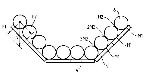
Figure 3 shows a cross section of a feeding device with
trunks loaded in and
Figures 4 and 5 show two different alternatives of the
feeder in cross section.
The barking drum Z is known in itself and there is no
need to describe it in more detail in this connection. In
front of the barking drum there is a trough-formed, open-
top feeding unit 2. Trunks or trunk bundles to be debarked
can be led either to the feeding unit 2 or in winter alterna
tively to the front end of the defrosting unit 3 in front
of the feeding unit 2 (figure 2). The defrosting unit can
also be connected straight to the drum in which case no
separate feeding unit between the defrosting unit and the
drum is required.
Sides of the bottom of the feeding unit 2 and the defrost-
ing unit 3 consist of several parallel longitudinal steel
bars or blocks ~. Top surface of the blocks 4 can be f.ex.
like a level or like V or V upside down in cross-sectional
shape. It is essential that all the surfaces of the block
that come into contact with material to be conveyed are
parallel with the feeding direction. Breadth of the blocks
can be.increased up to more than 50 cm by inclining the side
blocks. Main part of the bottom of the feeder are covered
by the blocks and the weight of the material to be conveyed
rests mostly on top of the blocks.
The blocks ~ are moved back and forth by hydraulic
cylinders 5 placed either in their ends or below them. The
feeding speed towards the drum 1 is only a fraction of the
speed of the return motion. It is essential that the total
breadth of the blocks in feed motion at a time is bigger
than the total breadth of the blocks in return motion at the
same time. Correspondingly, the speed of the return motion
must have the same proportion to the feed motion as the
_35 proportion of the total breadth of blocks in feed motion to
the total breadth of blocks in return motion.


4 a
Figure 3 shows a cross section of a feeding equipment in
accordance with the invention, loaded with trunks 6, which
enables a big transport capacity even for relatively big
trunks. Also the broad transfer elements 4 function well
because the side blocks 4' inclined towards the centre of
the conveyor effect fiction force M2 that grows schematically
in accordance with figure 3 M2, 2M2, 3M2 etc. A suitable in-
clination of blocks 4' effects a stronger friction force
between the trunks than the friction M1 between the trunks
and the blocks 4'. When the inclination of the side blocks
4' is 45°, the transport condition of the outermost block is
M2 > Ml with a horizontal conveyor.
For other blocks 4 the system in accordance with the
invention effects a considerably stronger friction between
the particles of the material than between the transfer
element 4 and the material.
Transport capacity of the outermost blocks 4' can be im-
proved by increasing their inclination angle f.ex. in accor-
dance with figures 4 and 5.
Transfer element arrangements in accordance with figures
_ 3, 9 and 5 also effect that during the return motion of the
block 4 the material tends to slide towards the centre of
the conveyor from the sides and to compress, which improves
the transport capacity.
The invention is not restricted to the applications pre-
sented above but it can be alternated within the framework of
the claims.
Hydraulic cylinders 5 can be fitted either to the end of
the blocks 4 or below them. The back and forth motion of the '
blocks 4 can be effected except with hydraulic cyl:irrders also
with any othex mechanism, f.ex, with an electric system or
with a tumbling shaft.
The top surface of the blocks can also be grooved parallel
with the feeding direction.
In case the bottom of the defrosting unit 3 in the
application in accordance with figure 2 is very much inclined


201~4~4
so that it slopes upwards in feeding direction the above de-
scribed blocks cannot be used as such, but they have to be
furnished with projections of a pusher type in order to make
sure that the feeded material rises upwards along the in-
s clined surface.
The invention can also be applied f.ex, to the feeding of
chip or bark. The equipment is suitable for conveyance of
any material in cases where a stronger friction force is
effected, by the inclined side blocks, between particles of
the material than the friction is between the blocks and
the material.
A very fluent feeding of the barking drum with wood can be
achieved by using a cross section of the feeding unit 2 in
accordance with figure 5, where the long trunks can be pre-
vented from breaking between the revolving barking drum 1
and the feeding unit 2. Because the feeding unit 2 according
to the invention has in feeding direction smooth surfaces on
the blocks 4, the feeding force is prevented from pushing the
whole drum.l violently forward. Currently used feeding
devices are equipped with pushers or jags that in certain
situations effect a force that breaks trunks or equipment.
In the new feeding unit 2 the trunks slide backwards when
necessary when the counterforce exceeds the friction.

Representative Drawing
A single figure which represents the drawing illustrating the invention.
Administrative Status

For a clearer understanding of the status of the application/patent presented on this page, the site Disclaimer , as well as the definitions for Patent , Administrative Status , Maintenance Fee  and Payment History  should be consulted.

Administrative Status

Title Date
Forecasted Issue Date 2001-08-07
(22) Filed 1990-06-06
(41) Open to Public Inspection 1991-01-03
Examination Requested 1997-05-14
(45) Issued 2001-08-07
Expired 2010-06-06

Abandonment History

There is no abandonment history.

Payment History

Fee Type Anniversary Year Due Date Amount Paid Paid Date
Application Fee $0.00 1990-06-06
Registration of a document - section 124 $0.00 1990-11-09
Maintenance Fee - Application - New Act 2 1992-06-08 $100.00 1992-05-15
Maintenance Fee - Application - New Act 3 1993-06-07 $100.00 1993-05-27
Maintenance Fee - Application - New Act 4 1994-06-06 $100.00 1994-05-19
Maintenance Fee - Application - New Act 5 1995-06-06 $150.00 1995-05-26
Maintenance Fee - Application - New Act 6 1996-06-06 $150.00 1996-05-14
Request for Examination $400.00 1997-05-14
Maintenance Fee - Application - New Act 7 1997-06-06 $150.00 1997-05-14
Maintenance Fee - Application - New Act 8 1998-06-08 $150.00 1998-05-19
Maintenance Fee - Application - New Act 9 1999-06-07 $150.00 1999-05-28
Maintenance Fee - Application - New Act 10 2000-06-06 $200.00 2000-05-11
Final Fee $300.00 2001-04-11
Maintenance Fee - Application - New Act 11 2001-06-06 $200.00 2001-05-23
Maintenance Fee - Patent - New Act 12 2002-06-06 $200.00 2002-05-17
Maintenance Fee - Patent - New Act 13 2003-06-06 $200.00 2003-05-20
Maintenance Fee - Patent - New Act 14 2004-06-07 $250.00 2004-05-17
Maintenance Fee - Patent - New Act 15 2005-06-06 $450.00 2005-05-27
Maintenance Fee - Patent - New Act 16 2006-06-06 $450.00 2006-05-24
Maintenance Fee - Patent - New Act 17 2007-06-06 $450.00 2007-05-28
Maintenance Fee - Patent - New Act 18 2008-06-06 $450.00 2008-05-23
Maintenance Fee - Patent - New Act 19 2009-06-08 $450.00 2009-05-22
Owners on Record

Note: Records showing the ownership history in alphabetical order.

Current Owners on Record
RAUMA-REPOLA OY
Past Owners on Record
JONKKA, ARVO
Past Owners that do not appear in the "Owners on Record" listing will appear in other documentation within the application.
Documents

To view selected files, please enter reCAPTCHA code :


To view images, click a link in the Document Description column. To download the documents, select one or more checkboxes in the first column and then click the "Download Selected in PDF format (Zip Archive)" or the "Download Selected as Single PDF" button.

List of published and non-published patent-specific documents on the CPD .

If you have any difficulty accessing content, you can call the Client Service Centre at 1-866-997-1936 or send them an e-mail at CIPO Client Service Centre.


Document
Description 
Date
(yyyy-mm-dd) 
Number of pages   Size of Image (KB) 
Representative Drawing 2001-07-25 1 7
Cover Page 2001-07-25 1 39
Drawings 1997-08-05 3 26
Cover Page 1993-11-20 1 15
Abstract 1993-11-20 1 21
Claims 1993-11-20 2 67
Drawings 1993-11-20 3 25
Description 1993-11-20 5 228
Description 1998-02-02 7 294
Claims 1998-02-02 4 204
Representative Drawing 1998-07-14 1 6
Assignment 1990-06-06 5 204
Prosecution-Amendment 1997-05-14 1 54
Correspondence 1990-11-16 4 84
Correspondence 2001-04-11 1 70
Prosecution-Amendment 1998-02-02 10 423
Fees 2001-05-23 1 54
Fees 1998-05-19 1 54
Fees 1999-05-28 1 56
Fees 2000-05-11 1 57
Fees 1997-05-14 1 63
Fees 1996-05-14 1 65
Fees 1995-05-26 1 60
Fees 1994-05-19 1 61
Fees 1993-05-27 1 54
Fees 1992-05-15 1 50