Note: Descriptions are shown in the official language in which they were submitted.
~ ~8~28
Contlnuously-operatlnq press
The present invention relates to continuously-operating
presses suitable for producing chipboard, plastic sheets,
plywood sheets or similar products.
Presses of this kind usually possessing flexible, endless
metal bands (usually made of steel) separated by an adjustable
press gap which serve to transmit pressing force to the
material to be pressed and to pull the material through the
press. The bands are supported by and circulate about the
press bed and press top upon drive rollers and deflection
rollers and run on roller rods whose axes are oriented
perpendicular to the direction of travel of the bands.
West German patent publication DE-OS 24 48 794 discloses a
continuously-operating press of this type wherein the angle of
the entry to the press gap can be adjusted by means of an
adjustment device located in the press top. In the prior art
adjustment device, a gerber beam located in the press top and
adjustable by means of raising or lowering the upper
deflection roller, rotates upon the rotational axis of an
intermediate roller and forms a rigid entry zone between both
rollers. The roller rods, when moving along a rigid transport
surface in the entry zone under varying pressure conditions
imposed by different process material, being thus unable
themselves to stabilize their longitudinal axis, are likely to
enter the high pressure zone out of precise rectilinear
alignment. The result of such misalignment is the uneven
spacing of the roller rods, and the risk of collision between
and damage to the roller rods.
A further disadvantage of the prior art press is that,
since the entry zone consists of a single transport surface,
the angle of the entry gap has to be adjusted about a single
rotational axis. The permissible bending and creasing load
for the steel band, however, requires that the radius of the
rotating shaft be at least 500 X greater than the thickness of
- 35 the steel band. The permissible bending/creasing load on the
steel band, however, restricts the entry-side angle to only
ca. 2O5O; otherwise, the wear on the steel bands at the
deflection point becomes too great. Both the production of
4 ~ 8
particle board having low-density top layers and system start-
up require a larger angle.
An object of the present invention is thus the design of
a continuously-operating press wherein the entry gap in the
entry zone of the press top can, during manufacture or
installation, be simply set-up in accordance with a
predetermined geometry and wherein a controlled adjustable and
controllable pressure profile can be applied to the roller
rods and whereby furthermore the entry zone allows the roller
rods, for the purpose of their auto-stabilization, a
sufficient degree of freedom.
According to one aspect of the invention there is
provided a continuously-operating press comprising (A) a press
frame; (B) a press bed and a press top connected to said press
frame and defining an adjustable press gap located
therebetween in a press zone; (C) first and second endless
steel bands adapted to transmit a pressing force to material
to be pressed and to draw said material through an entry gap,
an entry zone, and through said press zone, said entry zone
being supported on a support member and being divided into a
resilient rolling rod alignment zone and a rigid pressure
build-up zone; (D) drive rollers and deflection rollers
adapted to guide said first and second endless steel bands
around said press bed and said press top, respectively; (E) a
plurality of co-rotating roller rods adapted to support said
steel bands as they travel through said press, said roller
rods having axes of rotation transverse to a running direction
of said steel bands; and (F) an adjusting mechanism located
within said press and adapted to adjust said entry gap, said
adjusting mechanism comprising an articulated crosshead
anchored in said press frame and pivotable about an axis of
rotation, a pressure holding plate located within said entry
zone and adjustable about an axis of rotation and which is
adapted to act non-positively but resiliently on said roller
rods as they travel through said entry zone, and a plurality
of hydraulic supporting members located between said
articulated crosshead and said pressure holding plate and
~ ~84 ~8
which are adapted to act on said support member with a
pressure profile that increases continuously towards said
press zone.
According to another aspect of the invention there is
provided a press, comprising (A) a press frame; (B) a press
top and a press bed facing one another to define a press zone
therebetween; (C) band means for transmitting a pressing force
to material to be pressed and for drawing said material
through an entry gap, an entry zone, and through said press
zone, said entry zone being supported on a support member and
being divided into a resilient roller rod alignment zone and a
rigid pressure build-up zone; (D) a plurality of roller rods
adapted to support each of said band means as it draws said
material through said press; and (E) adjusting means, located
within said press, for adjusting said entry gap, said
adjusting means comprising an articulated crosshead anchored
in said press frame and pivotable about an axis of rotation, a
pressure holding plate located within said entry zone and
adjustable about an axis of rotation and adapted to act
non-positively but resiliently on said roller rods as they
travel through said entry zone, and supporting means, located
between said articulated crosshead and said pressure holding
plate, for acting on said support member with a pressure
profile that increases continuously towards said pressing
zone.
According to yet another aspect of the invention there is
provided a method of adjusting an entry gap of a press, said
press comprising a press frame, a press bed, a press top
facing the press bed to define a press zone therebetween, band
means for transmitting a pressing force to material to be
pressed and for drawing said material through said entry gap,
an entry zone, and through said press zone, said entry zone
being supported on a support member and being divided into a
resilient roller rod alignment zone and a rigid pressure
build-up zone, and a plurality of roller rods adapted to
support each of said band means as it draws said material
through said press, said method comprising the steps of (A)
2fl ~4 ~8
pivoting an articulated crosshead anchored in said press frame
and pivotable about an axis of rotation; (B) applying an
adjustable force to a pressure holding plate located within
said entry zone and adjustable about an axis of rotation so
that said pressure holding plate acts non-positively but
resiliently on said roller rods as they travel through said
entry zone; and (C) applying a pressure profile on said
support member that increases continuously towards said
pressing zone.
Thus, the angular adjustment of the entry gap can be
accomplished in accordance with the technical requirements
imposed by use of the material to be pressed. The present
invention furthermore provides a simple and effective means of
statically dividing entry zone I into flexible roller rod
realignment zone II and a rigid pressure buildup zone III.
A further advantage conferred by the present invention is
that the proposed method of angle adjustment enables, by
permitting adjustment during operation at maximum press force,
the establishment of a controlled but flexible pressure
profile.
The adjustment of the entry gap and the development of an
adjustable pressure profile to accommodate fluctuating
operating and material conditions is necessary because e.g.:
1. The manufacture of highly bend resistant particle board
having highly compressed top layers requires that the
entry gap be equal to the standard process material
thickness - i.e. the entry an~le should be approximately
zero.
2. The manufacture of lightweight sheets having low density
top layers requires that the entry gap be equal to two to
four times the reference thickness - i.e. the entry angle
should be approximately 2.5~ - 5~ and
3. The admission of particle board into the press at start-
up requires that the entry angle vary, according to the
precompressed thickness of the particle mass or press
material structure, between 0 and 5~.
2~ ~4~8
In the proposed methods, position "A", which refers to
the medial axis of the deflection roller and "B", which refers
to the beginning of the high pressure zone (reference
thickness of the finished press material) can be set in a
precise position. This arrangement provides for the creation,
between positions "A" and "B", in accordance with the pathway
sizes dictated by given material specifications, of entry
angles between 0 and ca. 5~. The roller rod alignment device
and pressure build up bridges operating in zones II and III of
the press top are supported via hydraulic adjusting members or
resilient elements against an articulated beam, which is
capable of rotating in the press top and about point "B", and
against the press bed and the steel band. The size of the
entry angle having to be commensurate with the allowable
bending/creasing load imposable upon the steel band, can be
regulated during press operation with the aid of an angle-
monitoring device. The controllable pressure profile, which
extends from the entry tangent over the roller rod alignment
device and pressure buildup bridge up to the high pressure
zone, requires the effective static separation of zones II and
III and IV by means of linkage systems. The proposed linkage
system, the resilient hydraulic support of the roller rod
alignment device and the permanent support of the pressure
build-up bridge against the steel band permit, during both
empty and loaded running, frictional contact between the
roller rods, the alignment device and the steel band, an
arrangement that has been found essential for the efficient
operation of an adjustable entry gap.
The press is preferably provided with a sensor, mounted
on the axis of one of the deflection rollers, for sensing the
position setting of the adjusting means and/or the thickness
of the material.
A preferred embodiment of the present invention is
described in the following with reference to the accompanying
drawings, in which:
Fig. 1 is a schematic side view of the proposed press;
6 ~ 4 ~ ~
Fig. 2 shows the entry zone of the press shown in Fig. 1,
showing the proposed angle adjustment device;
Fig. 3 shows the pressing force curve in entry zone I;
Fig. 4 shows the means of connection of the clamping
plate to the heating plate of the high pressure zone; and
Figs. 5 to 8 illustrate versions of joints for the
pressure buildup bridge, in positions "B" and "E".
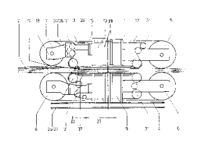
In Fig. 1, continuously-operating press 1 comprises press
bed 9, movable press top 10 and guide columns (not shown)
serving to connect both upper and lower press portions. Press
gap 11 is adjusted by sliding press top 10 up or down by means
of hydraulic piston-and-cylinder assemblies (not shown) until
the desired position is reached. Steel bands 3 and 4
circulate over drive rollers 5 and 6 and over deflection
rollers 7 and 8 of press bed 9 and press top 10, respectively.
Reduction of friction between heating plates 37 and 29,
belonging to press bed 9 and press top 10, respectively, and
circulating steel bands 3 and 4, is accomplished by the
interposition of a moving in a running direction co-rotating
roller rod carpet or ribbon comprising roller rods 12. The
rodsl whose axes run transversely relative to the travel
direction of the steel band, are fitted at predetermined
intervals, on both~longitudinal sides of press 1, into roller
chains 15. The roller rods roll, on one side, along the
heating plates 37 and 29 of press top 10 and press bed 9, and
on the other side along steel bands 3 and 4, and thus pull
along the process material 2 while moving through the press
gap.
It will also be appreciated from Fig. 1 that roller rods
12, by means of feed sprockets 24 and 25, and that roller
chains 15, by means of entry-side sprockets 26 and 27 disposed
on the sides of entry-side heating plate 30, are guided in
form-fit and fictionally-connective fashion into the
horizontal press plane. In the present embodiment, feed
sprockets 24, which are located on the press top 10, and feed
sprockets 25, which are located on press bed 9, as well as
entry sprockets 26, which are located on press top 10, and
20 18428
entry sprockets 27, which are located on press bed 9, are
attached to a common respective shaft. Reference numeral 33
marks the beginning of the zone of entry (entry tangent) of
roller rods 12 into the press zone; and reference numeral 23
marks the end of entry zone "E" as well as the beginning of
high pressure zone IV. The roller rods run about press bed 9
and press top 10 upon deflection rollers 31.
As Fig. 2 demonstrates, roller rods 12 are, beginning at
entry tangent 33, fed under increasing pressure into entry
zone I by means of feed sprockets 24 and 25. The rise of
pressure in entry zone I is illustrated in Fig. 3 by means of
a curve. The effective static separation of entry zone I into
roller rod alignment zone II and pressure build-up zone III as
well as high pressure zone IV, is accomplished by the
connection of such zones via a linkage system forming an
adjusting mechanism that begins at link point 18.
The adjustment of entry gap 11 by raising or lowering
deflection roller 7 from position "A" to position "A'" or vice
versa, is shown in Fig. 2. In this embodiment, entry angle
alpha is formed about position "B" or, in other words, axis of
rotation 19. The roller rod adjusting mechanism (not
illustrated) is borne resiliently via hydraulic adjusting
members 28 and 32 or via spring elements relative to an
articulated crosshead 13 and steel band 3. The roller rod
adjusting mechanism is movably borne and attached to a support
beam 35, to which entry-side heating plate 30 is also
attached, whereby support beam 35 can be fixed in any given
position with the aid of adjusting members 28 and 32. While
adjusting member 28 is permanently attached to articulated
30 crosshead 13, adjustment member 32 is rigidly supported in
press bed 9 at 17. Articulated crosshead 13 iS, in turn,
anchored in press frame 34 at "C" where it rotates about an
axis 38. Pressure build-up zone III is formed by articulated
plate 14, which, in this embodiment, is articulated at
position "B" in press frame 34 and at position "E" to entry-
side heating plate 30 or to support beam 35. Articulated
plate 14, while designed to rotate at position "B" about axis
2 ~ -~ 8 4 2 8
of rotation 19, can, in position "E", be rotated, raised or
lowered by means of a linkage system and the proposed
adjustment device. Due to the limited bending and creasing
load that can be supported by the steel band, the angles at
position "B" and position "E", which sits between the roller
rod alignment zone II and pressure build-up zone III or, in
other words, on one side, the angle at the joint between
support beam 35 (entry heating plate 30) and articulated plate
14 (pressure build-up bridge) and on the other side the angle
located between articulated plate 14 and heating plate 29,
should not exceed 2.5~. For this purpose, an angle size
monitor is installed in the adjustment cylinder of deflection
roller 7.
For reasons already discussed, development of a
controllable pressure profile in entry zone I requires the
effective static separation of zones II to IV by means of an
articulation system, as illustrated in Figs 5 to 8. In the
present embodiment, positions in B and E can be provided with
round hinges 20 or 21 and/or with curved turning faces 39 as
indicated in Figs 7 and 8. It will be appreciated from the
embodiment shown in Figs 7 and 8 that slippage does not occur
between turning beams 36 and 40.
In all of the articulation systems illustrated in Figs 5
to 8, the articulation region is covered by a flexible
clamping plate 16 (soft sheet metal), which permits roller
rods 12 to roll across a continuous surface. The smooth
transfer of roller rods 12 into high pressure zone IV is
ensured by providing the transition zone at "D" in Fig. 4 with
a sawtooth-like extension 22 of clamping plate 16. There is
also present at point "D" an expansion compensating factor "s"
between the faces of articulated plate 14 and first heating
plate 29 of high pressure zone IV. It is preferable if
clamping plate 16 be at the same time embodied as a resilient
plate serving the realignment of the roller rods.
Thus, roller rods 12 are able to advance with a degree of
freedom through the entry zone and between steel band 3 and
clamping plate 16. The latter, which is embodied as a leaf
.
~ ~ ~ 8 4 ~ 8
spring, is therefore fitted, without any rigid support means,
upon entry-side heating plate 30. In order to simplify the
drawing, the roller rods 12 are only alluded to in Figs 1 and
2, and entirely omitted in Figs 5 to 7.
Fig. 8 illustrates a preferred embodiment of the
articulation assembly operating at points "B" and "E", here
showing only the system at point "B". In Fig O 8I both
intermediate sheet 41 and clamping plate (soft metal sheet) 16
elastically and without support, span gap "l" under maximum
pressure. In this embodiment, the arrangement both of
intermediate sheet 41 and of clamping plate 16 in the manner
of a leaf spring, permits both former and latter to slide back
and forth between articulated plate 14 and first heating plate
29 of high pressure zone 14. Represented by a broken line,
articulated plate 14' has been rotated, together with clamping
plate 14' and intermediate sheet 41', through radius "R" about
point "B". Pressure is transmitted via concave joint 36, 39
and 40 to heating plate 29 and thence to press frame 34.