Note: Descriptions are shown in the official language in which they were submitted.
2018467
SV-230 (35-
LIQUID DISPENSING AND SUCTIONING SY~
FOR SURFACE CLEANING
BACKGROUND OF THE INVENTION
The invention relates to a system for
cleaning a surface. The system includes means for
storing a cleaning liquid, means for dispensing the
liquid to the surface to be cleaned and means for
suctioning the liquid along with any dirt, and the
like, that has been washed from the surface or
dissolved in the liquid from the surface.
The prior art includes wet/dry suctioning
systems which are adapted to pick up dispensed liquid
and wet materials from a surface. Such suctioning
systems typically include a collection tank, a take-up
hose for transmitting the liquid or the wet materials
from the surface to the collection tank and a suction
motor, typically communicating with the tank, for
generating a vacuum in the hose.
A surface can be cleaned more easily by
spreading a cleaning liquid, such as a solution of
water and detergent, across the surface. The surface
can be a floor, a carpet or other surface. The liquid
facilitates cleaning by dissolving and lifting off
dirt, and the like, from the surface to be cleaned.
Furthermore, the subsequent suctioning helps to dry the
surface or carpet by lifting away the liquid and wet
material from the surface.
- -~ 201846~
Accordingly, liquid dispensing and suctioning systems
have been developed to dispense cleaning liquid to a surface
or carpet to be cleaned and to thereafter suction the liquid
from the surface after the liquid has dissolved or lifted off
dirt, and the like. Some of these liquid dispensing and
suctioning systems are entirely self contained. Others are
developed as attachments to an intake hose or wand of a
stAn~Ard wet/dry suctioning system. The liquid may be
supplied to the attachment from an external source through a
hose or tube or the liquid may be carried on the cleaning
attachment within a tank.
In some systems, liquid may drip continuously through a
nozzle leading from a liquid supply container. However, it
is advantageous to selectively control the dispensing of
liquid from the liquid dispensing and suctioning systems.
Such control may be achieved, for example, by a manually
operable trigger for opening a dispensing nozzle or valve.
Liquid may be dispensed periodically or continuously.
In a system that is the subject of copending Canadian
Application No. 2,004,603, filed December 5, 1989, there is a
common unit that is applied at the carpet or the surface
being cleaned and which both delivers the liquid to the
carpet or surface and suctions up that liquid. If the liquid
dispensing outlet and suction nozzle of that unit are located
near each other, liquid dispensed through the outlet is
suctioned into the suction nozzle before it is delivered
to the carpet or surface. The liquid migrates along
the underside of the housing of the nozzle system
into the suction inlet without wetting
.~
X
-
2018467
3 --
the carpet or other surface and thus without cleaning
it. Enlarging the distance between the liquid outlet
and the suction nozzle enlarges the surface area of the
underside of the nozzle that contacts the carpet or
surface. Bringing the entire dispensing outlet to the
carpet or surface being cleaned has the same effect.
It is desirable to limit or reduce the surface area of
the nozzle contacting the carpet.
SU ~ARY OF THE INVENTION
Accordingly, it is an object of the invention
to provide an improved system for dispensing cleaning
liquid to a surface or carpet to be cleaned and for
subsequently suctioning the liquid along with dirt and
the like from the surface.
It is another object of the invention to
provide such a system which avoids suctioning up
dispensed liquid before it is delivered to the carpet
or surface being cleaned.
It is a further object of the invention to
minimize the surface area of the suction nozzle in
contact with the carpet or other surface being cleaned,
especially when a carpet is being cleaned, so that the
nozzle will normally press into the carpet for
affording more effective suction pickup.
The invention is directed to a liquid
dispensing and suctioning attachment for dispensing
liquid to a surface or carpet to be cleaned and for
suctioning the liquid along with dirt and the like from
the surface. The attachment is connectable through a
tube with a source of suction, like a suction motor at
a collection tank. The suction tube is included in a
-
2018~67
hand held tubular wand. There is a suction nozzle at
the end of the tube at the wand. The suction nozzle
has an inlet positionable adjacent the surface to be
cleaned for intake of the liquid, dirt, and the like,
and has an outlet fitting attached to an intake end of
the wand leading to the collecting container.
The attachment further includes a tank for
containing the liquid to be dispensed. The tank is
physically located at and is attached to the nozzle at
the end of the wand. However, the liquid to be
dispensed may be transmitted from a remote liquid
supply as well.
The attachment further includes a dispenser
for selectively dispensing the liquid to the surface to
be cleaned. The dispenser includes an actuator, means
for biasing the actuator toward a closed position to
retain the liquid in the tank and means for moving the
actuator to an open position to dispense the liquid to
the surface to be cleaned and a liquid dispensing
outlet in the form of a slot extending across the width
of the attachment, generally at its underside. Instead
of a single slot, the outlet may be defined by a series
of liquid outlet openings arranged across the
attachment which together effectively define a slot.
The suction nozzle inlet is also in the form of a slot
extending across the width of the attachment at its
underside. The suction inlet is near to and forward of
the dispensing outlet, and they extend parallel. The
dispensing outlet may be upraised above the suction
nozzle inlet at the bottom of the attachment.
The liquid dispensing outlet slot and the
suction nozzle are quite near each other, e.g. in a
-
- 5 - 2018467
common housing, as at the bottom of the tank. They are
so near to each other that when liquid is dispensed
from the dispensing outlet, which is typically above
the surface being cleaned, the liquid is sucked into
the suction nozzle inlet, without wetting or cleaning
the carpet or other surface. Bringing the entire
dispensing outlet slot, and particularly its periphery,
to the carpet or surface when combined with the suction
inlet, brings too large a surface area to the carpet.
The invention comprises providing a liquid
transmitting surface, located between the dispensing
outlet and the inlet to the suction nozzle and
positioned to contact the carpet or other surface.
This surface provides a conduit or transmission path
for the liquid and transmits it to the carpet or
surface. The suction inlet on the opposite side of the
liquid transmitting surface picks up the liquid from
the carpet or other surface. The liquid transmitting
surface may be a rib extending across the unit between
the dispensing outlet and suction nozzle. The rib is a
narrow element front-to-back, and extends straight
across the attachment. It is located near enough to
the suction nozzle that it does not significantly
enlarge the surface area of the attachment which is in
contact with the carpet.
Other objects and features of the present
invention will become apparent from the following
description of a preferred embodiment of the invention
considered in conjunction with the accompanying
drawings.
-
- 6 - 2018467
BRIEF DESCRIPTION OF THE DRAWINGS
Fig. 1 is a side view of the tank, dispensing
system, suction nozzle and lower wand section of a
preferred embodiment of the liquid dispensing and
suctioning system;
Fig. 2 is a cutaway side view which details
the lower portion of the features illustrated in
Fig. l;
Fig. 3 is a front view of the cascade
waterfall used with the preferred embodiment of the
attachment;
Fig. 4 is a rear view of the attachment; and
Fig. 5 shows one environment of use for the
system of the invention.
DESCRIPTION OF THE PREFERRED EMBODIMENT
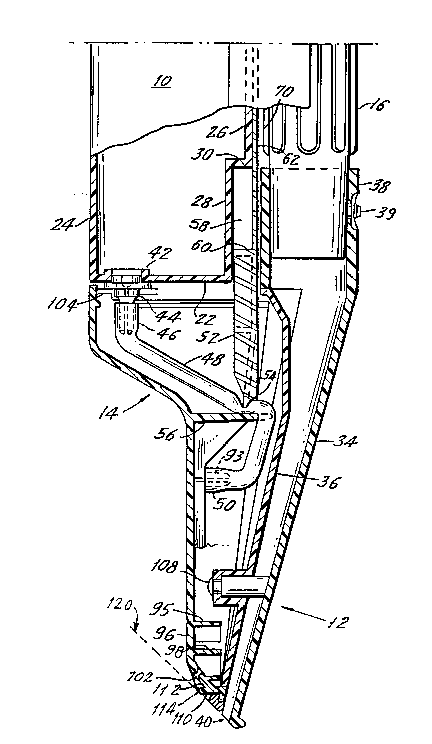
The preferred embodiment of the invention in
Figs. 1 and 9 includes a tank 10 for containing
cleaning liquid (not illustrated) therein, a nozzle 12
for delivering the liquid and a dispensing system 14
for valving the liquid from the tank to the nozzle.
The tank 10, the nozzle 12 and the dispensing system 14
are connectable to a tubular wand section 16 which in
turn is connectable to an upper, separate tubular wand
section 18. In operation, liquid is selectively and
controllably dispensed from the tank 10 to a surface to
be cleaned (not illustrated) to dissolve or lift off
dirt and the like from the surface. Suction is then
drawn from a below described suction source 130,
through the tube 124, wand sections 16 and 18, and then
through the nozzle 12 so that the liquid, along with
the dirt and the like, is drawn up through the nozzle
12 and out through the wand sections 16 and 18.
2018467
Except as otherwise indicated, the various
parts of the preferred embodiment of the system are
formed of molded, relatively rigid plastic.
Referring to Figs. 1 and 2, the tank 10 is a
total enclosure defined by an upper wall 20 away from
the nozzle 12, an opposite lower wall 22 at the bottom
of the tank, a back wall 24 which is at the side toward
the user and a front wall 26, which has the nozzle 12
and wand section 16 in front of it. The walls 20-26
enclose the tank. A recess 28 is defined in the tank
front wall 26 toward the lower wall 22 for receiving
and guiding vertical shifting of the below described
pinch slide 52. A ledge 30 defines the top of that
recess. A filler cap 32 is accessibly placed near the
top of the tank, through which the tank 10 may be
filled with liquid.
The suction nozzle 12 is preferably molded of
clear plastic, permitting observation of the liquid
being sucked through the nozzle. The nozzle has a
front cover 34 facing the front of the attachment and a
rear wall 36 at the front of the waterfall 96. An
outlet fitting 38 at the top of the nozzle connects it
to the wand section 16. The lower end of the lower
wand section 16 is retained in the outlet fitting 38 of
the nozzle 12 by means of a spring biased button detent
39. A suction inlet 40 at the bottom of the nozzle 12
is to be placed at the carpet or surface to be
suctioned. From its front side 141 to its rear side
142, the suction inlet is narrow all across the nozzle
12, to minimize the cross-section of the nozzle pressed
against the carpet, as discussed further below. The
cross-section of the nozzle 12 generally narrows in
2018~67
lateral side to side width and increases in front to
back height from the suction inlet 40 to the outlet
fitting 38.
The liquid dispensing system 14 includes an
outlet fitting 42 located at the lower wall 22 of the
tank 10. A connecting member 44 is spin-welded to the
outlet fitting 42. The inlet end 46 of a flexible,
resilient, preferably elastomeric rubber or plastic
tube 48 is pushed over and retained on the connecting
member 44. The opposite outlet end 50 of the tube 48
is held below the inlet end 46 and is maintained open
so that cleaning liquid can flow under the force of
gravity from the tank 10 through the connecting member
44, through the flexible tube 48 and then out past the
open outlet end 50.
The dispensing system 14 further includes a
tube pinch slide 52 which serves as an on-off valve for
flow through the tube 48. The slide 52 includes a
pinch tip 54 which is movable toward and away from a
shelf 56 that is molded in the dispenser wall 96 and
the shelf projects beneath the pinch tip 54. The
flexible tube 48 passes between the tip 54 and the
shelf 56. The slide 52 is biased down toward the shelf
56 by a compression spring 58. The compression spring
58 and a portion of the slide 52 are located within the
recess 28 and between the tank 10 and the nozzle 12.
The spring 58 is compressed between the ledge 30 of the
tank 10 and the rear end 60 of the slide 52. Thus, the
slide 52 is biased toward the shelf 56 so as to pinch
the flexible tube 48 between the tip 54 and the shelf
56. When the flexible tube 48 is pinched, cleaning
liquid cannot flow through the tube and is retained
within the tank 10.
2018467
A lower extension 62 extends up from the
slide 52. The extension 62 is used for pulling the
slide 52 away from the shelf 56 to open the tube 48
wh~ich permits dispensing of the liquid. The extension
62 is relatively thin front to back and wide laterally
so as to slide in front of the tank 10 and to the rear
of the nozzle 12. Details of the extension 62 are not
provided here. Generally, there are means 70 at the
wand section 18 enabling a user to pull on the
extension 62 and raise the slide 52. Details of this
means 70 are found in the above noted U.S. Application
No. 07/282,103. When the means 70 is pulled upwardly
manually, it pulls up the extension 62 which in turn
raises the slide 52 away from the nozzle 12 to open the
flexible tube 48. When the means 70 is released, the
compression spring 58 urges the slide 52 toward the
shelf 56 to pinch closed the flexible tube 48.
The lower outlet end 50 of the flexible tube
48 is received on a prong 93 projecting from the front
side of a cross-shaped initial flow divider 94. The
divider 94 initially dispenses the liquid flow as it
exits the tube 48. After the liquid falls off the
divider, it cascades and flows across a waterfall
arrangement 96 shown in Fig. 3. That arrangement is
located to the rear of the nozzle, and the rear wall of
the waterfall arrangement is typically inclined
downward and forward, so that the liquid runs down the
rear wall.
The waterfall arrangement 96 includes a first
plurality of inclined shelves 95 which move the
initially divided liquid laterally outward, through the
openings 97, over the inclined further dividing shelves
2018467
-- 10 --
98, onto the surface 99 and through the openings 100
over and through which the cleaning liquid cascades
downwardly toward outlets 102 in a progressively wider
pattern. Thus, the waterfall arrangement 96 serves to
evenly spread the cleaning liquid across the full width
of the waterfall arrangement which delivers liquid
through all of the outlets 102 and those outlets extend
over the full width of the suction inlet 40 of the
nozzle 12. The outlets 102 are in a row (Fig. 3) and
together define the dispenser outlet with a front side
143 that is toward or closer to the rear side 142 of
the suction inlet and a rear side 144 that is further
away from the rear side 142 of the suction inlet.
The present invention is directed toward
assuring that liquid which has been dispensed through
outlets 102 across the entire width of the nozzle be
delivered onto the carpet or surface being cleaned and
is not instead suctioned up before wetting that carpet
or surface. Directly beneath in the drip path of
liquid from the outlets 102, and slightly forward of
the outlets 102 to be between the rear side 142 and the
front side 143, the outlets 102 and extending laterally
across the nozzle, a liquid transfer surface 110 is
defined in the bottom wall 112 of nozzle. The surface
110 is preferably in the form of a continuous rib
across the bottom wall 112. The rib 110 extends toward
the carpet or other surface 120 while the outlets 102
and the front and rear sides 143 and 144 of the outlets
are upraised off the carpet being cleaned so that in
the normal orientation of the unit with respect to the
carpet, as shown in Fig. 2, the free edge 114 of the
rib 110 contacts and presses into the carpet 120.
2018467
Cleaning liquid, carpet shampoo, or the like exits the
outlets 102, either drips straight down or migrates
along the wall 112 and then along the surface or rib
110 to the carpet. The carpet fibers attract the
liquid by capillary action, like a wick, and spread the
cleaning solution before it is suctioned through the
suction inlet 40. The edge 114 of surface or rib 110
contacts the carpet or surface 120 far enough from the
inlet 40 that the carpet will receive liquid before it
is suctioned. Yet, the surface or rib 110, and
particularly its edge 114, is near enough to the
suction inlet 40 that the cross-sectional area of the
surface of the nozzle in contact with the carpet, and
particularly its front to rear width, is minimized to
enable the suction nozzle to press into the carpet,
both under its own weight and by user pressure, to
improve suctioning from the carpet pile.
After the cleaning liquid is dispensed
through the openings 102 and onto the surface 120 to be
cleaned, the liquid and collected dirt is then sucked
through the suction inlet 40 from the surface to be
cleaned. As shown in Fig. 5, the upper wand section
18, which is hand held, is connected through a flexible
hose 124 into the tank 126 of a conventional wet/dry
pickup, tank type electric vacuum or suction cleaner
130. A vacuum is drawn in the hose and wand section
and suction nozzle 12 by a conventional blow motor 132
seated atop the tank which sucks air and liquid through
the hose. The collected liquid falls into the tank 126
while the air is exhausted out of the outlet 134.
Although the invention has been described in
connection with a preferred embodiment thereof, many
2018~67
- 12 -
variations and modifications may become apparent to
those skilled in the art. It is preferred, therefore,
that the invention be limited not by the specific
disclosure herein, but only by the appended claims.