Language selection

Search

Patent 2018608 Summary

Third-party information liability

Some of the information on this Web page has been provided by external sources. The Government of Canada is not responsible for the accuracy, reliability or currency of the information supplied by external sources. Users wishing to rely upon this information should consult directly with the source of the information. Content provided by external sources is not subject to official languages, privacy and accessibility requirements.

Claims and Abstract availability

Any discrepancies in the text and image of the Claims and Abstract are due to differing posting times. Text of the Claims and Abstract are posted:

  • At the time the application is open to public inspection;
  • At the time of issue of the patent (grant).
(12) Patent: (11) CA 2018608
(54) English Title: FUEL INJECTION
(54) French Title: INJECTION DE COMBUSTIBLE
Status: Expired and beyond the Period of Reversal
Bibliographic Data
(51) International Patent Classification (IPC):
  • F02M 51/00 (2006.01)
  • F02M 51/02 (2006.01)
  • F02M 69/50 (2006.01)
(72) Inventors :
  • STETTNER, ERNEST R. (United States of America)
  • STOLTMAN, DONALD D. (United States of America)
  • TAYLOR, ROLAND S. (United States of America)
(73) Owners :
  • GENERAL MOTORS CORPORATION
(71) Applicants :
  • GENERAL MOTORS CORPORATION (United States of America)
(74) Agent: GOWLING WLG (CANADA) LLP
(74) Associate agent:
(45) Issued: 1994-10-18
(22) Filed Date: 1990-06-08
(41) Open to Public Inspection: 1990-12-21
Examination requested: 1990-06-08
Availability of licence: N/A
Dedicated to the Public: N/A
(25) Language of filing: English

Patent Cooperation Treaty (PCT): No

(30) Application Priority Data:
Application No. Country/Territory Date
07/369505 (United States of America) 1989-06-21

Abstracts

English Abstract


An injector has a single tapered valve controlling fuel
flow to a plurality of outlet passages. The entrance
to each outlet passage has an orifice surrounded by a
raised valve seat. Each valve seat is separated from
the other valve seats by a recessed space. The valve
pivots as it is displaced from the valve seat to allow
fuel flow through the outlet passages, and is
constrained against other motion within the injector.
The valve seats are clustered beneath the free end of
the valve. The orifices are sized to compensate for
the unequal lift of the tapered valve from the valve
seats.


Claims

Note: Claims are shown in the official language in which they were submitted.

Claim
1 - An injector comprising a distributor having a
plurality of outlet passages and an orifice at the
entrance of each of said passages and a valve seat
surrounding each of said orifices, a tapered valve
biased to engage said valve seats to interrupt fuel
delivery through said outlet passages, a valve actuator
adapted to pivotally displace said valve from said
valve seats to allow fuel delivery through said
passages, said valve pivoting about one end thereof as
it is displaced whereby the lift of said valve from the
valve seat furthest from said end of said valve is
greater than the lift of said valve from the valve seat
closest to said end of said valve, and wherein said
orifices are sized to compensate for the differences in
lift of the valve from the associated valve seats, the
orifice associated with the valve seat closest to said
end of said valve being larger than the orifice
associated with the valve seat furthest from said end
of said valve.

Description

Note: Descriptions are shown in the official language in which they were submitted.


2018608
G-1513 C-4163
FUEL INJECTION
Technical field
This invention relates to a fuel injection system for a
multi- cylinder internal combustion engine in which a
plurality of injection nozzles discharge fuel adjacent
the engine inlet ports and a single injector meters the
fuel to all of the injection nozzles.
Summary of the drawings
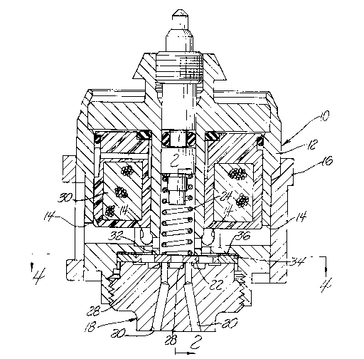
Figure 1 is a sectional view of a single injector that
meters fuel to six injection nozzles in accordance with
this invention.
Figure 2 is an enlarged sectional view of the lower
portion of the Figure 1 injector, taken along the line
2-2 of Figure 1, showing the injector valve engaging
its seat.
Figure 3 is a view similar to Figure 2, showing the
injector valve lifted from its seat.
Figure 4 is an enlarged sectional view of the Figure 1
injector, taken along line 4-4 of Figure 1 and with
various portions broken away, showing the relationship
of the injector valve and the orifices through which
the injector meters the fuel to the injection nozzles.
' ~
~F

2~186~8
Detailed description
Referring to the drawings, an injector 10 has a body 12
that receives fuel through a plurality of radial inlet
passages 14 surrounded by a filter 16. A distributor
18 threaded into the lower end of body 12 delivers fuel
through six outlet passages 20, each of which directs
fuel to an associated injection nozzle.
A valve 22 controls the delivery of fuel through
passages 20. As shown in Figure 2, valve 22 is biased
by a spring 24 to engage a planar surface 26 formed by
raised valve seats or lands 28, each surrounding one of
the passages 20, and thereby interrupt fuel delivery
through passages 20.
Injector 10 includes a solenoid having a coil 30, a
center pole 32 surrounding spring 24, a ring spacer 34
surrounding valve 22 and sandwiched with a shim 36
between body 12 and distributor 18, and an armature
formed by valve 22. Valve 22 is tapered from its
thickest portion on the left as viewed in Figures 2-3
to its thinnest portion on the right. When coil 30 is
energized as shown in Figure 3 to actuate valve 22, the
thickest portion of valve 22 engages shim 36 and causes
the valve to pivot about its left edge, thereby lifting
from lands 28 to allow fuel delivery through passages
20.
Each land 28 is separated from the other lands by the
recessed space 38 between the lands. The recessed
space 38 assures that each land 28 is isolated from the

21~186û8
other lands to minimize the effect or interaction of
fuel delivery through any one passage 30 on fuel
delivery through the other passages.
Because valve 22 pivots as it lifts from lands 28, the
clearance between valve 22 and lands 28a and 28b is
less than the clearance between valve 22 and lands 28c
and 28d which in turn is less than the clearance
between valve 22 and lands 28e and 28f. Unless
otherwise compensated, the differences in clearance
would create undesirable inequalities in fuel delivery
through passages 20.
To minimize the differences in clearance, passages 20
are clustered beneath the right or free end of armature
valve 22, and pins 40 hold valve 22 in alignment with
passages 20. Pins 40 are imbedded in distributor 18
and constrain the movement of valve 22 to the pivotal
motion described above, preventing valve 22 from
rotating on distributor 18.
To compensate for the remaining differences in
clearance, the orifices 42 formed at the entrance to
each passage 20 are sized to assure equal fuel delivery
through passages 20. Orifices 42a and 42b associated
with lands 28a and 28b are larger than orifices 42c and
42d associated with lands 28c and 28d, and orifices 42c
and 42d in turn are larger than orifices 42e and 42f
associated with lands 28e and 28f. In one embodiment,
the clearance between valve 22 and lands 28a and 28b is
about 0.0056 and the diameter of orifices 42a and 42b
is about 0.041, the clearance between valve 22 and
lands 28c and 28d is about 0.0060 and the diameter of

20 1 8608
orifices 42c and 42d is about 0.0395, and the clearance
between valve 22 and lands 28e and 28f is about 0.0065
and the diameter of orifices 42e and 42f is about
0.038. (Dimensional units are not provided; only the
proportions are significant.)
';~,~ ,

Representative Drawing
A single figure which represents the drawing illustrating the invention.
Administrative Status

2024-08-01:As part of the Next Generation Patents (NGP) transition, the Canadian Patents Database (CPD) now contains a more detailed Event History, which replicates the Event Log of our new back-office solution.

Please note that "Inactive:" events refers to events no longer in use in our new back-office solution.

For a clearer understanding of the status of the application/patent presented on this page, the site Disclaimer , as well as the definitions for Patent , Event History , Maintenance Fee  and Payment History  should be consulted.

Event History

Description Date
Inactive: IPC from MCD 2006-03-11
Time Limit for Reversal Expired 1999-06-08
Letter Sent 1998-06-08
Grant by Issuance 1994-10-18
Application Published (Open to Public Inspection) 1990-12-21
All Requirements for Examination Determined Compliant 1990-06-08
Request for Examination Requirements Determined Compliant 1990-06-08

Abandonment History

There is no abandonment history.

Owners on Record

Note: Records showing the ownership history in alphabetical order.

Current Owners on Record
GENERAL MOTORS CORPORATION
Past Owners on Record
DONALD D. STOLTMAN
ERNEST R. STETTNER
ROLAND S. TAYLOR
Past Owners that do not appear in the "Owners on Record" listing will appear in other documentation within the application.
Documents

To view selected files, please enter reCAPTCHA code :


To view images, click a link in the Document Description column. To download the documents, select one or more checkboxes in the first column and then click the "Download Selected in PDF format (Zip Archive)" or the "Download Selected as Single PDF" button.

List of published and non-published patent-specific documents on the CPD .

If you have any difficulty accessing content, you can call the Client Service Centre at 1-866-997-1936 or send them an e-mail at CIPO Client Service Centre.


Document
Description 
Date
(yyyy-mm-dd) 
Number of pages   Size of Image (KB) 
Claims 1993-11-04 1 22
Drawings 1993-11-04 2 108
Abstract 1993-11-04 1 16
Description 1993-11-04 4 99
Abstract 1994-10-17 1 17
Description 1994-10-17 4 106
Claims 1994-10-17 1 25
Drawings 1994-10-17 2 118
Representative drawing 1999-07-29 1 35
Maintenance Fee Notice 1998-07-05 1 179
Fees 1996-05-23 1 43
Fees 1997-05-22 1 47
Fees 1993-05-24 1 40
Fees 1994-05-24 1 55
Fees 1995-05-24 1 52
Fees 1992-05-24 1 46
PCT Correspondence 1994-07-28 1 33
Courtesy - Office Letter 1990-11-18 1 21
Prosecution correspondence 1993-03-28 5 169
Examiner Requisition 1993-01-28 1 183