Language selection

Search

Patent 2018715 Summary

Third-party information liability

Some of the information on this Web page has been provided by external sources. The Government of Canada is not responsible for the accuracy, reliability or currency of the information supplied by external sources. Users wishing to rely upon this information should consult directly with the source of the information. Content provided by external sources is not subject to official languages, privacy and accessibility requirements.

Claims and Abstract availability

Any discrepancies in the text and image of the Claims and Abstract are due to differing posting times. Text of the Claims and Abstract are posted:

  • At the time the application is open to public inspection;
  • At the time of issue of the patent (grant).
(12) Patent: (11) CA 2018715
(54) English Title: CABLE HOOK
(54) French Title: CROCHET PROTE-CABLE
Status: Expired and beyond the Period of Reversal
Bibliographic Data
(51) International Patent Classification (IPC):
  • F16G 11/14 (2006.01)
  • B63B 21/08 (2006.01)
  • F16G 11/04 (2006.01)
(72) Inventors :
  • KAYE, SYDNEY P. (Canada)
(73) Owners :
  • WIRE ROPE INDUSTRIES LTD. - INDUSTRIES DE CABLES D'ACIER LTEE
(71) Applicants :
  • WIRE ROPE INDUSTRIES LTD. - INDUSTRIES DE CABLES D'ACIER LTEE (Canada)
(74) Agent: PRIMAK & CO.
(74) Associate agent:
(45) Issued: 1993-06-29
(22) Filed Date: 1990-06-11
(41) Open to Public Inspection: 1991-12-11
Examination requested: 1992-09-25
Availability of licence: N/A
Dedicated to the Public: N/A
(25) Language of filing: English

Patent Cooperation Treaty (PCT): No

(30) Application Priority Data: None

Abstracts

English Abstract


Abstract of the Disclosure
A cable hook for securing a cable comprises an
elongated body member having a longitudinal aperture
generally rectangular in cross-section formed therein and
provided on one sidewall with two oppositely tapered
surfaces, a cable receiving slot formed between an outer
surface of the body member and the aperture for laterally
inserting a portion of a cable into the aperture against one
wall opposed to the tapered sidewall, a second aperture
extending through the body member at approximately right
angle to the first aperture, first and second wedge members
located in the longitudinal aperture and each provided with
an inner surface adapted to engage the cable and an outer
tapered surface matching one of the tapered surfaces in the
longitudinal aperture and adapted to slide thereon, and a
third wedge member insertable in the second aperture and
having tapered surfaces for driving the first and second
wedge members in opposite direction along their associated
tapered surfaces for clamping the portion of the cable
inserted into the longitudinal aperture of the hook.


Claims

Note: Claims are shown in the official language in which they were submitted.

-8-
CLAIMS
1. A cable hook for securing a cable comprising:
a) an elongated body member having a longitudinal
aperture generally rectangular in cross-section formed
therein and provided on one sidewall with two oppositely
tapered surfaces;
b) a cable receiving slot formed between an outer
surface of said body member and said aperture for laterally
inserting a portion of a cable into said aperture against one
wall opposed to the tapered sidewall;
c) a second aperture extending through said body
member at approximately right angle to the first aperture;
d) first and second wedge members located in said
longitudinal aperture and each provided with an inner surface
adapted to engage the cable and an outer tapered surface
matching one of the tapered surfaces in the longitudinal
aperture and adapted to slide thereon;
e) a third wedge member insertable in said second
aperture and having tapered surfaces for driving said first
and second wedge members in opposite direction along their
associated tapered surfaces for clamping the portion of the
cable inserted into the longitudinal aperture of the hook.
2. A cable hook as defined in claim 1, wherein said first
and second wedge members are provided with a two-level
tapered surface with an intermediate step therebetween for
allowing the wedge members to drop onto the cable with less
longitudinal travel.

-9-
3. A cable hook as defined in claim 1, wherein a groove is
formed into one wall of the longitudinal aperture and keys
formed into the mating surface of the first and second wedge
members, said groove being parallel to the tapered surfaces
of the first and second wedge members and terminating short
of the opposed ends of the body member so as to prevent
dropping of the wedge members from the hook.
4. A cable hook as defined in claim 1, further comprising
a pin for locking said third wedge member when the wedge is
driven in position.

Description

Note: Descriptions are shown in the official language in which they were submitted.


~als-~ls
CA~
This invention relates to a cable hook, and more
particularly to a cable hook for use in ~oining individual
bundles of logs in a log raft.
A log raft is normally formed of a plurality of log
S bundles assembled together, each bundle being made up o~
several individual logs seaured together using conventional
wire rope straps and fittings. The bundles are usually
assembled in the wood and transported by truck to the water
where they are assembled together into a raft. In assembling
a raft, several bundles are arranged side by side to form a
row and several rows of log bundles are lined up end to end
between a head boom stick and a tail boom stick. wire ropes
are used to interconnect the head and tail boom sticks
longitudinally and a wire rope known as a swifter line is
lS used to contain the bundles laterally in each row. The
/ ~k

- - 20~71~
.,
-2-
swifter lines are secured to the longitudinal lines using
conventional cable hooks such as the one disclosed in
Canadian Patent No. 1,158,422.
One problem encountered with conventional cable hooks
is that they often become loose when the cable is pulled in a
direction opposite to the direction that the wedge member of
the cable hook is driven, which happens frequently when
maneuvering a log raft on a body of water.
It is therefore the ob~ect of the present invention to
provide a hook having oppositely working wedge members so
that pulling on the rope clamped into the hook in either
direction will not loosen the hook from the rope.
The hook in accordance with the present invention
comprises an elongated body member having a longitudinal
aperture therein generally rectangular in cross-section and
provided on one sidewall with two oppositely tapered surfaces
one at each end thereof, a cable receiving slot formed
between an outer 5urface of the body member and ~uah aperture
for laterally inserting a portion of a cable into the
aperture against one wall opposed to the tapered sidewall, a
second aperture extending through the body member at
approximately right angle to the longitudinal aperture, first
and second wedge members located in the longitudinal aperture
and each provided with an inner surface adapted to engage the
cable and an outer tapered surface matching one of the
tapered surface in the longitudinal aperture and being

~O~g7~
--3--
slidable thereon, and a third wedge member insertable into
the second aperture and having tapered surfaces for driving
the first and second wedge members in opposite directions
along their associated tapered surfaces to clamp the portion
of the cable inserted into the longitudinal aperture of the
hook.
The ~irst and second wedge members are preferably
provided with a two-level taperad ~urface with an
intermediate step allowing the wedge members to drop onto the
cable with far less longitudinal travel.
A groove is preferably formed into one wall of the
longitudinal aperture and keys formed into the mating
surfaces of the first and second wedge members. The groove
is parallel to the tapered surfaces of the first and second
wedge members and terminate short of the opposed longitudinal
ends of the body member to prevent dropping of the wedge
members from the hook.
A pin is preferably provided for locking the third
wedge member when driven in flnal position.
The invention will now be disclosed, by way of example,
with reference to the accompanying drawings in which:
Figure 1 is a schematic view of a floating log raft
employing cable hooks in accordance with the present
invention;
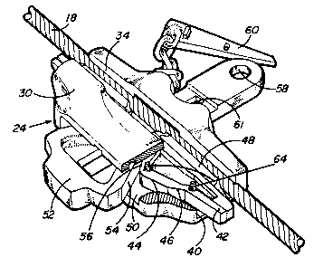
25 ~ Figure 2 is a perspective front view of the cable hook
in accordance with the present invention with one portion cut

--` 2~ ~7I~
away to show one of the inner wedge members; and
Figure 3 is a perspective rear view of the cable hook
with one portion cut away to show inside grooves for guiding
the wedge members.
Referring to Figure 1, there is shown a log raft
comprising several bundles lO of logs assembled together by
means of en¢ircling wire ropes or straps 12 cinched together
by conventional Pittings. The bundle~ are assembled in
sevèral rows between a head boom stick 14 and a tail boom
stick 16 using longitudinal wire ropes 18 which are threaded
under the encircling wire ropes 12 and attached at each end
to the boom sticks. The bundles in each row are held
together by means of swifter lines 22 which are attached at
their extremities to the longitudinal lines 18 using cable
hooks 24 made in accordance with the present invention.
Referring to Figures 2 and 3, the hook comprises an
elongated body member 30 having a longitudinal aperture 32
formed therein with a cable receiving slot 34 formed between
the outer surface of the body member 30 and the internal
aperture for laterally inserting a portion of the cable 18
into the aperture. The aperture is generally rectangular in
cross-section and is provided with a cable engaging surface
38 on one wall thereof and two oppositely tapered surfaces 40
on the opposed wall, one at each end of the hook. Two wedge
members 42 are mounted one at each end of the aperture. Each
wedge member is provided with a two-level tapered surface 44

-- 2 a ~
-5-
adapted to engage one of the tapered surfaces 40 of the
aperture. A step 46 is provided in the two-level tapered
surface 44. This is another feature of the present invention
which allows the wedge to drop onto the cable with far less
longitudinal travel than current wedge hooks in the field,
thus affording a shorter and therefore lighter fixture. A
gripper plate 48 made of hardenod ~teel is welded or
otherwise secured to the cable engaging surface of the wedge
member 42. The gripper plate is preferably provided with
teeth to adequately grip the cable.
A second aperture 50 is provided through the body
member at approximately 90- from the first aperture. A third
wedge member 52 is inserted in the second aperture and is
provided with tapered surfaces 54 adapted to engage matching
tapered surfaces 56 on wedge members 42 to force the wedge
members 42 to slide outwardly and thus clamp the cable 36.
During installation, a hook i5 attached to each end of
a swifter line by passing the end of the swifter line through
a hole 58 in the end of the wedge member 52 as shown in
Figure 3 of the drawings. The hooks are attached to a
longituidnal wire rope 18 at both extremities of a row of log
bundles by inserting the wire rope into the slot 34 of the
hooks. The wedge member 52 of each hook is then driven in
with a hammer to force the wedge members 42 into engagement
with the wire rope to clamp the rope. The other rows of

2~ 871~
bundles are attached to the longitudinal wire ropes the same
way.
The two wedge members 42 provide oppositely acting
wedging surfaces generating increased clamping action during
pulling of the cable in either direction, thus allowing the
log raft to be towed in either direction.
As illustrated in Figure 2 a pln 60 may be provided for
insertion into a slot 61 in wedge member 52 for preventing
the wedge from loosening up after it has been driven in
position.
It is also desirable to arrange the wedge members 42
within the body 30 so that they will not fall off when the
hook is not engaged with a cable and additionally to
facilitate the operation of the hook. Therefore, as shown in
Figure 3, a groove 62 i9 formed into one wall o the aperture
32 and a pair of keys 64 provided on the mating surface of
each wedge member 42. Groove 62 parallels the taper o the
wedge surface 44 includlng the step 46 and terminates short
of the opposed ends of the body 30. A transverse groove 66
is provided at the centre of the groove to permit insertion
and removal of the wedge members 42 into and from the
aperture 32, through the second aprture 50.

-- 20i~71~
-7-
Although, the invention has been disclosed by way of
example, with reference to a preferred embodiment, it is to
be understood that it is not limited to such embodiment and
that other alternatives are also envisaged within the scope
of the following claims.

Representative Drawing
A single figure which represents the drawing illustrating the invention.
Administrative Status

2024-08-01:As part of the Next Generation Patents (NGP) transition, the Canadian Patents Database (CPD) now contains a more detailed Event History, which replicates the Event Log of our new back-office solution.

Please note that "Inactive:" events refers to events no longer in use in our new back-office solution.

For a clearer understanding of the status of the application/patent presented on this page, the site Disclaimer , as well as the definitions for Patent , Event History , Maintenance Fee  and Payment History  should be consulted.

Event History

Description Date
Inactive: IPC from MCD 2006-03-11
Inactive: Office letter 2004-06-09
Letter Sent 2004-05-26
Inactive: Multiple transfers 2004-04-20
Inactive: Multiple transfers 2004-04-02
Time Limit for Reversal Expired 2002-06-11
Letter Sent 2002-02-13
Inactive: Office letter 2001-06-13
Appointment of Agent Requirements Determined Compliant 2001-06-13
Revocation of Agent Requirements Determined Compliant 2001-06-13
Inactive: Office letter 2001-06-13
Letter Sent 2001-06-11
Letter Sent 2000-10-24
Inactive: Multiple transfers 2000-09-13
Inactive: Multiple transfers 2000-07-18
Grant by Issuance 1993-06-29
All Requirements for Examination Determined Compliant 1992-09-25
Request for Examination Requirements Determined Compliant 1992-09-25
Application Published (Open to Public Inspection) 1991-12-11

Abandonment History

There is no abandonment history.

Fee History

Fee Type Anniversary Year Due Date Paid Date
MF (patent, 8th anniv.) - standard 1998-06-11 1998-04-09
MF (patent, 9th anniv.) - standard 1999-06-11 1999-04-27
MF (patent, 10th anniv.) - standard 2000-06-12 2000-04-19
Registration of a document 2000-09-13
Registration of a document 2000-11-09
Registration of a document 2002-01-03
Registration of a document 2004-04-02
Owners on Record

Note: Records showing the ownership history in alphabetical order.

Current Owners on Record
WIRE ROPE INDUSTRIES LTD. - INDUSTRIES DE CABLES D'ACIER LTEE
Past Owners on Record
SYDNEY P. KAYE
Past Owners that do not appear in the "Owners on Record" listing will appear in other documentation within the application.
Documents

To view selected files, please enter reCAPTCHA code :


To view images, click a link in the Document Description column. To download the documents, select one or more checkboxes in the first column and then click the "Download Selected in PDF format (Zip Archive)" or the "Download Selected as Single PDF" button.

List of published and non-published patent-specific documents on the CPD .

If you have any difficulty accessing content, you can call the Client Service Centre at 1-866-997-1936 or send them an e-mail at CIPO Client Service Centre.


Document
Description 
Date
(yyyy-mm-dd) 
Number of pages   Size of Image (KB) 
Abstract 1994-07-08 1 24
Claims 1994-07-08 2 43
Drawings 1994-07-08 2 59
Description 1994-07-08 7 177
Representative drawing 1999-07-14 1 18
Maintenance Fee Notice 2001-07-08 1 178
Correspondence 2001-05-30 4 127
Correspondence 2004-06-08 1 13
Fees 1997-04-09 1 58
Fees 1996-04-10 1 52
Fees 1993-06-01 1 28
Fees 1995-05-11 1 43
Fees 1994-05-12 1 41
Fees 1992-05-21 1 28
Prosecution correspondence 1992-10-26 1 26
PCT Correspondence 1993-04-12 1 20
Prosecution correspondence 1992-09-24 1 24
PCT Correspondence 1991-08-19 2 79
Courtesy - Office Letter 1991-08-29 1 48
Courtesy - Office Letter 1992-10-15 1 39
Courtesy - Office Letter 1991-08-29 1 47