Note: Descriptions are shown in the official language in which they were submitted.
- 2~ 7~
CONTROL SYSTEM
BACKGROUND OF TllE INVENTION
This invention relates generally to a control
system for use with a fabric washing machine and more
particularly to a control system operable for disabling
the fabric washing machine if the contacts of a lid
actuated switch fail in the conductive posture.
In the operation of a fabric washing machine,
a lid actuated switch in circuit connection with the
operating apparatus is commonly utilized. The contacts
of this switch are generally closed when the lid is
closed and are open when the lid is open so that
operation of the fabric washing machine is normally
interrupted whenever the lid is open. Thus, if the
contacts of the lid actuated switch should fail in
the closed posture, such as by welding, the washing
machine will still be operational when the lid is open.
Prior art has shown an ongoing search for
a control system through which an appliance is placed
in a disabled condition if a particular switch should
fail in a conductive posture when a non-conductive
posture is normal. In the field of microwave ovens,
for example, opening the access door will effect the
opening of a pair of series connected switches so that
if one switch fails in a conductive posture the other
switch will be in a non-conductive posture for preventing
energization of the oven with the access door open.
2 ~ 27
-
Also shown in the field of microwave ovens are circuits
where opening the access door again normally opens
a pair of series connected switches. If one of these
switches should fail in the conductive posture, a circuit
is provided for blowing a fuse to prevent energization
of the oven.
There has not been any provision of a control
system in which an appliance, such as a fabric washing
machine, will be disabled if the lid switch contacts
fail in the conductive posture with the lid in the
open position and in response to a predetermined
operational condition of the fabric washing machine.
SUMMARY OF THE INVENTION
It is therefore an object of the instant
invention to provide an improved control system for
a fabric washing machine.
It is a further object of the instant invention
to provide a control system operable for disabling the
fabric washing machine when a lid switch has failed and
responsive to a condition of the fabric washing machine.
It is a still further object of the instant
invention to provide a control system with a lid switch
mechanism including switch mounting apparatus movable
for providing concurrent adjustment of at least a pair of
switches with respect to a lid actuated switch operator.
Briefly, the instant invention achieves these
objects in a control system for a fabric washing machine
2 ~ 2~
having a movable lid for providing access to a tub
assembly. The control system includes a power supply
and a first switch in circuit with the power supply
and operable between conductive and non-conductive
postures. A second switch is in circuit with the first
switch and is operable between a lid-closed first con-
ductive path and a lid-open second conductive path.
Apparatus is provided for operating the first and second
switches. The control system further includes a third
switch responsive to a condition of operation of the
fabric washing machine. A lockout is provided in circuit
with the third switch and the second conductive path
of the second switch for interrupting operation of
the fabric washing machine and preventing reenergization
thereof upon failure of the first switch to operate
to the non-conductive posture.
Operation of the control system and further
objects and advantages thereof will become evident
as the description proceeds and from an examination
of the accompanying four sheets of drawings.
BRIEF DESCRIPTION OF THE DRAWINGS
The drawings illustrate a preferred embodiment
of the invention with similar numerals referring to
similar parts throughout the several views, wherein:
Figure 1 is an isometric view of a fabric
washing machine utilizing the control system of the
instant invention;
27
Figure 2 is a partial fragmentary section view
taken generally along lines 2-2 of Figure 1 and showing
the lid actuated switches of the instant invention;
Figure 3 is a partial fragmentary section
view taken generally along lines 3-3 of Figure 2;
Figure 4 is a fragmentary view taken generally
along lines 4-4 of Figure 3 showing the attachment
of a frame portion of the lid actuating mechanism to
the top cover of the fabric washing machine;
Figure 5 is a fragmentary view taken generally
along lines 5-5 of Figure 3;
Figure 6 is a partial electrical schematic
drawing of the operational circuitry of the instant
invention; and
Figure 7 is a schematic drawing of the oper-
ational circuitry of an alternate embodiment.
DESCRIPTION OF A PREFERRED EMBODIMENT
Referring now to the drawings and to Figures
1 and 2 in particular, there is shown an automatic
fabric washing machine 10. The automatic fabric washing
machine 10 is housed within a generally rectangular
cabinet having a three-sided enclosure forming the
sides 11 and rear 12 of the cabinet. A substantially
vertically oriented front panel 13 completes the
peripheral cabinet of the fabric washing machine 10.
The cabinet of the fabric washing machine 10 further
includes a generally horizontally disposed top cover
2~ 9~
14 incorporating a pivotable access door or lid 15
for providing access to the interior of the fabric
washing machine 10. A control housing 16 extends
generally upward from the rear of the top cover 14
and houses miscellaneous controls such as selection
switches 19 and in this embodiment an electromechanical
timer 20, shown in dashed lines in Figure 1, for con-
trolling the sequential operation of the fabric washing
machine 10 through a plurality of events such as filling
the tub 21 with washing fluid, dispensing detergent
and/or bleach, agitation, washing fluid extraction,
and rinsing which comprise a predetermined cycle of
operations. As best shown in Figure 2, the top cover
14 includes an access opening 22 through which fabrics
may be inserted into or removed from the tub 21. The
access opening 22 is closed by the access door or lid
15 which is pivoted about a fulcrum 23 spaced a short
distance from the rear end 24 of the lid 15. The rear
end 24 of the lid 15 functions as a lever with respect
to the fulcrum 23 for engaging the switch actuating
and unbalance mechanism 2S.
The switch actuating and unbalance mechanism
25 has a molded plastic frame 26 which is attached
to the underside of the top cover 14 by a pair of screws
29, as best shown in Figure 4, which extend through
a substantially vertical wall 30 associated with the
access opening 22 of the top cover 14 and thread into
- 2~ t ~7
the frame 26. A plunger 31 is slidingly supported
within the frame 26. The front end 32 of the plunger
31 is in the form of a projecting nose which extends
generally horizontally through the vertical wall 30
associated with the access opening 22 of the top cover
14 and contacts the rear end 24 of the lid 15. The
frame 26 is generally hollow and supports the plunger
31 for substantially horizontal sliding movement to
the right and/or left depending on the posture of the
lid 15. The rear end 33 of the plunger 31 has a down-
wardly extending flange 34 which contacts and slides
relative to the horizontally extending portion 54 of
the unbalance mechanism 25. The plunger 31 further
includes an undercarriage 35 for pivotally supporting
the combination unbalance lever and lid switch actuator
36 on the plunger 31 and which will be further described
herein.
As best shown in Figures 2 and 3, the top
cover 14 has a downwardly formed generally T-shaped
opening 39 spaced rearwardly from the access opening
22 and axially aligned with the switch actuating and
unbalance mechanism 25. The T-shaped opening 39 is
covered by the control housing 16 when it is fastened
to the top cover 14. The T-shaped opening 39 serves
first as a hand-hold for handling the top cover 14
during manufacturing operations and when assembled
as part of the fabric washing machine 10 provides an
4 2~7
opening between the interior of the control housing
16 and the interior of the fabric washing machine 10.
As further shown in Figures 2, 3, and 5,
a generally rectangular switch mounting bracket 40
is secured to the top cover 14 so that it substantially
overlies the T-shaped opening 39. As best shown in
Figure 3, one side of the switch mounting bracket 40
includes a pair of spaced-apart downwardly extending
tabs 41 which are received by a pair of slots 42 formed
in the top cover 14. The pair of slots 42 are generally
parallel with the front-to-rear axis of the switch
actuating and unbalance mechanism 25 and permit the
switch mounting bracket 40 to move in a sliding fashion
a predetermined front-to-rear distance upon the top
cover 14. The opposite side of the switch mounting
bracket 40 has a slot 43 which is generally parallel to
the pair of slots 42 in the top cover 14. The slot 43
in the switch mounting bracket 40 overlies an extruded
aperture 44 in the top cover 14, as best shown in Figure
5, which receives a locking fastener 45 for securing
the switch mounting bracket 40 to the top cover 14.
The central portion of the switch mounting
bracket 40 further includes an opening 46 which is
axially aligned with the front-to-rear path of the
unbalance lever and lid switch actuator 36. As again
shown in Figures 2 and 3, the forward edge 49 of the
switch mounting bracket 40 has a forwardly extending
- ~31~
tongue S0 which, as best shown in Figure 2, rides in
the narrowed front-to-rear portion 51 of the T-shaped
opening 39 to reduce twisting movement of the switch
mounting bracket 40 during sliding movement thereof
with respect to the top cover 14. The tongue 50 sub-
stantially fills the narrowed front-to-rear portion
51 of the T-shaped opening 39 and with the main body
of the switch mounting bracket 40 provides a vapor
barrier between the control housing 16 and the interior
of the fabric washing machine 10.
As previously described and as shown in Figure
2, the unbalance lever and lid switch actuator 36 is
pivotally supported by the undercarriage 35 of the
plunger 31 and includes a depending lever 52 extending
substantially downward from the pivot connection between
the unbalance lever and lid switch actuator 36 and
the plunger 31. The depending lever 52 is positioned
for engagement by the bumper 53 upon excessive gyration
of the tub 21 to pivot the unbalance lever and lid
switch actuator 36 downwardly to the dashed line posture
shown in Figure 2 for interrupting operation of the
fabric washing machine 10. The unbalance lever and
lid switch actuator 36 further includes a horizontally
extending portion 54 having an upturned end 55 which
extends angularly upward and to the right in Figure
2 through the T-shaped opening 39 in the top cover
14 and through the opening 46 in the switch mounting
s4~r
bracket 40. As the access door or lid 15 is closed
and opened, the unbalance lever and lid switch actuator
36 is moved a predetermined linear rearward and forward
distance respectively.
A biasing spring 56 is operably disposed
between the unbalance mechanism frame 26 and the
unbalance lever and lid switch actuator 36. This biasing
spring 56 provides upwardly and forwardly directed
components of biasing force. The upwardly directed
component of force maintains the horizontally extending
portion 54 of the unbalance lever and lid switch actuator
36 against the rear flange 34 of the plunger 31. The
forwardly directed component of force biases the unbalance
lever and lid switch actuator 36 and the plunger 31
in a forward direction to maintain engagement of the
nose of the plunger 31 with the rear end 24 of the
access door or lid 15.
The switch mounting bracket 40 i.s designed
to rigidly mount a pair of switches 59 and 60 and a
fuse holder 61. A single-pole single-throw lid switch
59 is secured to the switch mounting bracket 40 overlying
the opening 46. The actuator button 62 of the lid
switch 59 is juxtaposed to the upturned end 55 of the
- unbalance lever and lid switch actuator 36. The lid
switch 59 is mounted to the switch mounting bracket
40 with the actuator button 62 tilted at an angle with
respect to the top surface 63 of the switch mounting
- 20l~
bracket 40. The angular mounting tilts the lower front
edge 64 of the lid switch 59 with respect to the upturned
end 55 of the unbalance lever and lid switch actuator
36. Thus, there will be no interference with the lower
front edge 64 of the lid switch 59 after an unbalance
situation in which the unbalance lever and lid switch
actuator 36 have been pivoted below the switch mounting
bracket 40. A single-pole double-throw switch 60 is
mounted forwardly of the lid switch 59 and also overlies
the opening 46 in the switch mounting bracket 40. The
actuator button 65 of the switch 60 is juxtaposed the
opposite side of the upturned end 55 and faces the
actuator button 62 of the lid switch 59.
It is noted, with respect to Figures 2 and
3, that the facing switch actuator buttons 62 and 65
are a fixed horizontal distance apart. As best shown
in Figure 2, the switch actuator buttons 62 and 65
are arranged at different heights with respect to the
top surface 63 of the switch mounting bracket 40 to
insure that the unbalance lever and lid switch actuator
36 will properly move upward between the switches 59
and 60 as the lid 15 is raised and then lowered after
an unbalance situation.
As best shown in Figure 5, an upwardly extending
wall 66 is located to the left of the opening 46 for
protecting the actuator buttons 62 and 65 of the switches
59 and 60 from interference with miscellaneous wires.
-- 10 --
20~9~l27
As further shown in Figure 5, a pair of downwardly
extending guides 69 are molded alongside the opening
46 in the switch mounting bracket 40. The guides 69
are tapered towards the opening 46 in the switch mounting
bracket 40 to guide the unbalance lever and lid switch
actuator 36 toward the opening 46.
The switch mounting bracket 40 with the rigidly
mounted switches 59 and 60 is slidable on the top cover
14 to provide for simultaneous adjustment of the switches
59 and 60 with respect to the upturned end 55 of the
unbalance lever and lid switch actuator 36. In normal
operation, it is desired that the lid switch 59 open
first as the lid 15 is opened. Also, the lid switch
59 should be the last to close as the lid 15 is closed.
Adjustment of the switch mounting bracket 40 is thus
made primarily with respect to the lid switch 59.
The switch mounting bracket 40 is moved with respect
to the slots 42 so that there is continuity across
the lid switch 59 with the correct opening between
the front edge of the lid 15 and the top cover 14.
In this posture, the switch 60 will be closed to contact
84 to permit operation of the fabric washing machine
10 .
It is further shown in Figures 2 and 3 that
the switch mounting bracket 40 mounts a fuse holder
61. The fuse holder 61 is conveniently positioned
2 ~ 7
behind the lid switch 59 and is thus located for easy
accessibility if replacement of the fuse 70 is required.
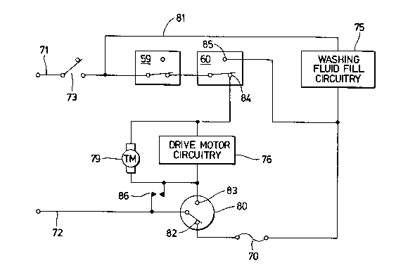
Turning now to Figure 6, there is shown a
partial schematie drawing of the lid switch circuit of
the instant invention. The eireuit ineludes a souree of
power as provided by standard 120 VAC between conduetors
71 and 72 and commonly available in most households. A
line switch 73 is ineorporated in the internal circuitry
of the eleetromechanical timer 20 and is operated by
manipulating the timer control knob 74. The circuit
further ineludes the single-pole single-throw lid switch
59, the single-pole double-throw switch 60, washing
fluid fill eircuitry 75, drive motor circuitry 76,
a timer drive motor 79, a pressure actuated washing
fluid level switch 80 and a fuse 70.
The washing fluid fill cireuitry 75 shown
in bloek form in Figure 6 eomprises hot and eold washing
fluid valves, switehes for providing various eombinations
of hot and cold washing fluid and various timer switehes
operated by timer eams driven by the timer drive motor
79. The drive motor eireuitry 76 also shown in bloek
form comprises the drive motor start and run windings,
speed switch, overload protector and various timer
switches operated by timer cams driven by the timer
drive motor 79.
The circuitry of Figure 6 is arranged so
that when the line switch 73 is closed but the lid 15
- 12 -
~19~!27
is open, the lid switch 59 will be in the non-conductive
posture. A circuit will be completed by way of an
internal timer bus connection 81 to the washing fluid
fill circuitry 75 and if the washing fluid level switch
80 is made to the empty or fill contact 82, the circuit
will be completed to conductor 72 of the power supply
and the fabric washing machine 10 will fill with washing
fluid with the lid 15 either open or closed. Energization
of the drive motor circuitry 76 and energization of
the timer drive motor 79 cannot occur until the washing
fluid level switch is made to the full contact 83 as
the fill is completed and the lid 15 is closed to actuate
the lid switch 59 to the conductive posture and to
actuate the switch 60 to the first conductive posture
at contact 84.
During normal operation of the fabric washing
machine 10, a cycle of operations can be interrupted
at any point by merely opening the lid 15 to move the
unbalance lever and lid switch actuator 36 in the forward
direction to first actuate the lid switch 59 to the
non-conductive posture. The act of opening the lid
15 will also normally actuate the switch 60 to the
second conductive posture at contact 85 which, as shown
in Figure 6, bypasses the washing fluid fill circuitry
75 and is in series circuit connection with the fuse
70 and the empty or fill contact 82 of the washing
fluid level switch 80. In the event that the lid switch
- 13 -
27
59 is welded or otherwise fixed in the closed posture
when the lid 15 is opened with tub 21 empty, a circuit
is completed from conductor 71, through the line switch
73, through the failed closed lid switch 59, through
the switch 60 made to the second conductive posture
at contact 85, through the fuse 70 and through the
empty or fill contact 82 of the washing fluid level
switch 80 to conductor 72. This will cause full line
current to pass through the fuse 70 and will quickly
destroy the fuse 70 to disable the fabric washing machine
10 and prevent the next fill of washing fluid.
If the lid switch 59 is welded and the lid
15 is opened during the cycle when the tub 21 is full
of washing fluid and the full contact 83 of the washing
fluid level switch 80 is made, a circuit to the fuse
70 will not be completed since the washing fluid level
switch 80 is made to the full contact 83. In this
case, the switch 60 will, in effect, act as a back-up
lid switch and will interrupt the cycle of operations
since power is discontinued to the drive motor circuitry
76 and timer drive motor 79. As further shown in Figure
6, a cam actuated timer switch 86 is open during fill
and closed during spin or washing fluid extraction
portions of a cycle. Thus, a bypass circuit is provided
around the washing fluid level switch 80 for independent
operation of the drive motor circuitry 76 so that the
~ 0 ~ 7
drive motor circuitry 76 and timer drive motor 79 do
not operate through the full contact 83.
The circuit through the fuse 70 can only be
completed, in the preferred embodiment, when the washing
fluid level switch 80 is made to the empty or fill
contact 82 such as after a fluid extraction portion
of a cycle and at the end of a cycle of operations.
Then, when the lid 15 is opened with the lid switch
59 welded or failed in the conductive posture, the
fuse 70 will be destroyed and the fabric washing machine
10 will be disabled. This disablement will require
that the fabric washing machine 10 be serviced to replace
the faulty lid switch 59 and the destroyed fuse 70.
During an unbalance situation where the bumper
53 has moved the unbalance lever and lid switch actuator
36 to the dashed line posture of Figure 2, the lid
switch 59 will be opened to the non-conductive posture
but the switch 60 will remain in the first conductive
posture at contact 84. The unbalance mechanism 25
is reset by opening and closing the lid 15 which will
close the lid switch 59 to the conductive posture and
allow the cycle of operations to continue.
Referring now to Figure 7, there is shown
an alternate circuit embodiment. In this alternate
embodiment, closing the line switch 73 with the control
knob 74 will allow the fabric washing machine 10 to
fill with the lid 15 either open or closed in a circuit
- ~01~7
similar to that shown in Figure 6. Energization of
the drive motor circuitry 76 and energization of the
timer drive motor 79 cannot occur until the washing
fluid level switch 80 is made to the full contact 83
as the fill is completed and the lid 15 is closed to
operate the switch 60 to the lid-closed first conductive
posture at contact B4. Once the fluid level switch
80 is made to the full contact 83, an electromechanical
actuator such as a solenoid 89 is energized to close
switch 88 which, in this embodiment, may be located
away from the switch mounting bracket 40. A lid latching
mechanism including a switch operating solenoid as in
the alternate embodiment of Figure 7 is fully described
in United States Patent 4,623,179 issued November 18,
1986 to Davis et al and assigned to the assignee of
the present invention. Closing switch 88 will complete
a circuit to the drive motor circuitry 76 through switch
60 made to lid-closed contact 84 to permit operation
of the fabric washing machine 10. It is anticipated,
in the circuit of Figure 7, that the solenoid 89 may
be utilized to operate a lid latching mechanism as
shown and described in United States patent 4,623,179
in addition to operating switch 88 to the conductive
posture as the tub 21 is filled.
Once again, if switch 88 is welded or other-
wise fixed in the closed posture with the lid 15 open
and with tub 21 empty, a circuit will be completed
- 16 -
2D1~7
as previously described for Figure 6. Specifically,
the circuit extends from conductor 71, through the
line switch 73, through the switch 88, through the
switch 60 made to the lid-open second conductive posture
at contact 85, through the fuse 70 and through the
empty or fill contact 82 of the washing fluid level
switch 80 to conductor 72. This will again permit
full line current to pass through fuse 70 for disahling
the fabric washing machine 10 and preventing the next
fill of washing fluid.
The control system as described herein provides
for improved operation of a fabric washing machine.
The control system provides for disablement of the
fabric washing machine if the contacts of the lid switch
are detected to be welded or otherwise fixed in the
conductive posture and in response to a predetermined
operational condition of the fabric washing machine.
The control system is arranged so that the switch 60
will function as a back-up lid switch during the cycle
of operations and the fabric washing machine will not
be disabled with a full tub of washing fluid.
The control system of the preferred embodiment
as described herein further provides for adjustment
of the actuators of the lid switches relative to the
unbalance lever and lid switch actuator. The switches
are mounted in a stationary posture on the mounting
bracket and the mounting bracket is adjustable with
2~1~42~
respect to the top cover and unbalance lever and lid
switch actuator to position the mounting bracket and
switches for proper actuation.
In the drawings and specification, there has
been set forth a preferred embodiment of the invention
and although specific terms are employed, these are
used in a generic and descriptive sense only and not
for purposes of limitation. Changes in the form and
the proportion of parts as well as the substitution
of equivalents are contemplated as circumstances may
suggest or render expedient without departing from
the spirit or scope of the invention as further defined
in the following claims.
- 18 -