Language selection

Search

Patent 2019541 Summary

Third-party information liability

Some of the information on this Web page has been provided by external sources. The Government of Canada is not responsible for the accuracy, reliability or currency of the information supplied by external sources. Users wishing to rely upon this information should consult directly with the source of the information. Content provided by external sources is not subject to official languages, privacy and accessibility requirements.

Claims and Abstract availability

Any discrepancies in the text and image of the Claims and Abstract are due to differing posting times. Text of the Claims and Abstract are posted:

  • At the time the application is open to public inspection;
  • At the time of issue of the patent (grant).
(12) Patent: (11) CA 2019541
(54) English Title: RIBBON TRANSDUCERS
(54) French Title: TRANSDUCTEURS A RUBAN
Status: Expired and beyond the Period of Reversal
Bibliographic Data
(51) International Patent Classification (IPC):
  • H04R 1/02 (2006.01)
  • H04R 9/00 (2006.01)
  • H04R 9/04 (2006.01)
(72) Inventors :
  • BANK, GRAHAM (United Kingdom)
  • PINFOLD, HAROLD C. (United Kingdom)
(73) Owners :
  • CELESTION INTERNATIONAL LIMITED
(71) Applicants :
  • CELESTION INTERNATIONAL LIMITED (United Kingdom)
(74) Agent: CASSAN MACLEAN
(74) Associate agent:
(45) Issued: 1995-07-18
(22) Filed Date: 1990-06-21
(41) Open to Public Inspection: 1990-12-21
Examination requested: 1993-10-14
Availability of licence: N/A
Dedicated to the Public: N/A
(25) Language of filing: English

Patent Cooperation Treaty (PCT): No

(30) Application Priority Data:
Application No. Country/Territory Date
8914283.0 (United Kingdom) 1989-06-21

Abstracts

English Abstract


A ribbon transducer has the ends of its ribbon (10)
held by end fixings which incorporate damping means.
The end fixing may include a resilient support member
(18) fixed to the ribbon (10), with the ribbon
overlying a pad (22) of damping material and having its
outer end held clamped, or alternatively left free.


Claims

Note: Claims are shown in the official language in which they were submitted.

-4-
CLAIMS:
1. A ribbon transducer comprising an
elongate, electrically conductive, vibratable ribbon
having two oppositely disposed ends, and a support
member at at least one end of the ribbon, in which the
support member comprises an elastic member affixed to
the ribbon at a position spaced from the end of the
ribbon, and in which fixed-position mounting means
fixedly hold the elastic support member, thereby to
create a ribbon tail endwise of the fixing of the
support member and which is relieved of stress.
2. A ribbon transducer according to claim 1,
in which the support member is affixed to the underside
of the ribbon.
3. A ribbon transducer according to claim 1,
in which the ribbon tail outwardly of the position at
which the ribbon is fixed to the support member
overlies a pad of damping material held between the
ribbon and the support member.
4. A ribbon transducer according to claim 3,
in which the ribbon tail beyond the pad is held clamped
by clamping means.
5. A ribbon transducer according to claim 4,
in which the clamping means also provides a locating
means for the support member.
6. A ribbon transducer according to claim 2,
in which the ribbon tail outwardly of the position at
which the ribbon is fixed to the support member is
turned back on itself, and both the end of the ribbon
and the end of the support member remote from its
contact with the ribbon are fixedly mounted.
7. A ribbon transducer according to claim 1,
2 or 3, in which the support member is a thin strip of
material.
8. A ribbon transducer according to claim 1,

2 or 3, in which the support member has a thickness of
the order of 0.5mm.

Description

Note: Descriptions are shown in the official language in which they were submitted.


2019541
RIBBON TRANSDUCERS
SPECIFICATION
This invention relates to ribbon transducers, and
is particularly concerned with the mounting of such
transducers, for example in loudspeakers and
microphones.
Conventionally, ribbon transducers have simply been
10 clamped at their ends to a rigid support. Over a
period of time this rigid clamping of the ends of the
ribbon can lead to fracture of the ribbon or at least
to a degradation in its performance.
It is an object of the present invention to provide
15 an improved end mounting for a ribbon transducer,
particularly for a ribbon transducer to be used in a
loudspeaker.
In accordance with the present invention this is
achieved by the use of an end fixing which incorporates
20 damping means.
By the provision of a damped mounting at each end
of the ribbon the danger of cracking or fracturing of
the ribbon is avoided or at least substantially reduced
without in any way adversely affecting the performance
25 of,the transducer.
In order that the invention may be more fully
understood, a number of embodiments of end mounting for
the ribbon of a ribbon transducer in accordance with
the invention will now be described by way of example
30 and with reference to the accompanying drawings, in
which:
Fig. 1 is an isometric view of a preferred
embodiment of end mounting;
Fig. 2 is an illustration of one alternative end
35 mounting; and,

2019S41
Fig. 3 is a schematic view of a further alternative
end mounting.
Referring first to Fig. 1, there is shown a ribbon
foil 10 which constitutes the active element of a
5 ribbon transducer, for example for a loudspeaker. The
end portion of the ribbon foil 10 is clamped between a
terminal block 12 and a clamping bar 14. The terminal
block 12 is provided with a surface groove 16 of
arcuaLe cross-section across its width. This groove 16
10 provides a seat for a support member 18. The support
member 18 is made of a resilient material, for example
silicone rubber, and may have a thickness of the order
of 0.5mm. At one end the support member 18 is provided
a bead 20 which is seated in the groove 16 as a
15 locating means. The bead 20 may be glued in place.
The other end of the support member 18 is glued or
otherwise secured to the underside of the ribbon foil
10. The central portion of the support member 18
carries a foam damping pad 22 which is of generally
20 semi-circular shape in cross-section as viewed from the
side of the foil. The ribbon foil 10 passes over the
damping pad 22, as shown in the drawing.
This resilient/damping end mounting for the ribbon
foil 10 provides the necessary security against
25 fracture at the ends of the ribbon.
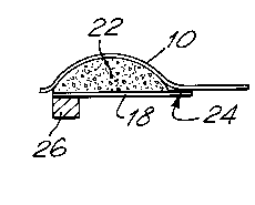
Fig.2 shows one alternative mounting arrangement.
Here, the support member 18 has one end glued to the
ribbon foil 10, as indicated at 24. The other end of
the support member 18 is rigidly fixed to a mounting
30 bar 26. In this arrangement the end of the ribbon
foil, after passing over the damping pad 22, extends
freely. The portion of the foil 10 which passes over
the damping pad 22 is glued to the pad.
Fig. 3 shows yet a further alternative end
35 mounting. Here the end portion of the ribbon foil 10

-
2019~41
is turned back on itself through 180 and is secured at
its end to a fixed-position block 28. The one end of
the support member 18 is glued, at 24, to the ribbon
foil 10 and the other end of the support member 18 is
5 fixed to a mounting block 26. This arrangement again
provides a resilient damping at the end of the ribbon
foil sufficient to reduce the danger of fracture.
Various other alternative methods of mounting the
ribbon foil at its ends may be devised within the scope
10 of the present invention.

Representative Drawing
A single figure which represents the drawing illustrating the invention.
Administrative Status

2024-08-01:As part of the Next Generation Patents (NGP) transition, the Canadian Patents Database (CPD) now contains a more detailed Event History, which replicates the Event Log of our new back-office solution.

Please note that "Inactive:" events refers to events no longer in use in our new back-office solution.

For a clearer understanding of the status of the application/patent presented on this page, the site Disclaimer , as well as the definitions for Patent , Event History , Maintenance Fee  and Payment History  should be consulted.

Event History

Description Date
Inactive: IPC from MCD 2006-03-11
Time Limit for Reversal Expired 1998-06-22
Letter Sent 1997-06-23
Grant by Issuance 1995-07-18
Request for Examination Requirements Determined Compliant 1993-10-14
All Requirements for Examination Determined Compliant 1993-10-14
Application Published (Open to Public Inspection) 1990-12-21

Abandonment History

There is no abandonment history.

Owners on Record

Note: Records showing the ownership history in alphabetical order.

Current Owners on Record
CELESTION INTERNATIONAL LIMITED
Past Owners on Record
GRAHAM BANK
HAROLD C. PINFOLD
Past Owners that do not appear in the "Owners on Record" listing will appear in other documentation within the application.
Documents

To view selected files, please enter reCAPTCHA code :


To view images, click a link in the Document Description column. To download the documents, select one or more checkboxes in the first column and then click the "Download Selected in PDF format (Zip Archive)" or the "Download Selected as Single PDF" button.

List of published and non-published patent-specific documents on the CPD .

If you have any difficulty accessing content, you can call the Client Service Centre at 1-866-997-1936 or send them an e-mail at CIPO Client Service Centre.


Document
Description 
Date
(yyyy-mm-dd) 
Number of pages   Size of Image (KB) 
Abstract 1995-07-18 1 11
Cover Page 1995-07-18 1 17
Description 1995-07-18 3 98
Drawings 1995-07-18 1 23
Claims 1995-07-18 2 47
Representative drawing 1999-07-27 1 4
Maintenance Fee Notice 1997-09-15 1 179
Fees 1996-07-22 1 49
Fees 1995-06-29 2 99
Correspondence 1995-08-23 1 18
Fees 1994-05-27 1 36
Fees 1993-06-08 1 26
Fees 1992-05-27 1 25
Prosecution correspondence 1993-10-14 4 93
PCT Correspondence 1995-05-10 1 39
Courtesy - Office Letter 1994-12-09 1 19
Courtesy - Office Letter 1994-10-17 1 19
Courtesy - Office Letter 1994-05-09 1 18
PCT Correspondence 1994-11-09 6 179
PCT Correspondence 1994-08-09 4 127
Courtesy - Office Letter 1993-11-02 1 56
Prosecution correspondence 1993-10-14 1 35
Courtesy - Office Letter 1991-07-26 1 19
Courtesy - Office Letter 1990-09-14 1 53