Note: Descriptions are shown in the official language in which they were submitted.
20 1 q&23
-- 1 --
RELATIVE ELECTROMYOGRAPHIC MUSCLE
REFLEX A~llVllY DURING MOTION
BACKGROUND OF THE INVENTION
The present invention relates to
determinations of relative muscular reflex activity
during contractions and lengthenings of the body
muscle involved as reflected in corresponding
electromyographic signals and, more particularly, to
such determinations made when the muscular
contractions and extensions are involved with
rotations of skeletal joints.
The control of the contracting and lengthening
of muscles in the human body has long been known to
have both a volitional aspect involving the central
portions of the central nervous system and a reflex
aspect involving peripheral portions of the central
nervous system. In this latter aspect, the stretching
of a typical muscle is sensed by a muscle spindle
embedded therein and signals indicating such
stretching are provided over afferent neurons to the
system of spinal neurons. From there, return signals
are provided over the alpha motor neurons, or efferent
neurons, to the muscle body causing it to contract to
counteract the initial stretching. This "local"
feedback loop is the basis of reflex actions in the
muscle involved.
In the former, or volitional, control aspect,
a first mode of control has signals from the central
portion of the central nervous system provided along
the spinal nerve complex into the peripheral portion
of the central nervous system. From there they are
transmitted over alpha motor neurons to the muscle
body to again cause it to contract.
- 2 - 2nl q~ 23
However, the central portion of the central
nervous system is also known to be able to affect or
modulate the reflex actions of such a muscle. Thus,
the level of signals in the reflex feedback loop
described above appear subject to being increased (or
decreased) under control of the central portion, i.e.
in effect, the "gain" of that control loop can be
changed by the central portion. Such a change in this
stretch reflex feedback loop gain, i.e. modulation of
the stretch reflex, is thought possibly to be due to
signals provided from the central portion to the gamma
motor neuron which extends to the muscle spindle or to
influences exerted by the central portion on loop
neurons (or interneurons) in the spinal nerve complex.
Whatever the means, there is substantial evidence that
movement of the muscle under volitional control is
given effect not only through direct signals
transmitted from the central portion of the central
nervous system through the spinal nerves and over the
alpha motoneuron to the muscle, but also through the
central portion transmitting signals having the effect
of modulating the stretch reflex.
As is well known, muscles in moving structural
portions of which they are comprised, and other bodily
structures to which such muscles are connected, are
capable of being forced to contract in length but, in
the other direction, are merely permitted to lengthen
under some externally applied tensile force. That is,
lengthening of a muscle cannot be forced solely by
signals transmitted over motor neurons to that muscle.
Thus, skeletal joints in the human body are operated
by pairings of muscles to permit them to be rotated in
opposite directions.
- - 20 1 9.~23
A member of such a muscle pair for such a
skeletal joint is provided more or less on opposite
sides of that joint and each is capable of rotating
the actuator portion of that joint, with respect to
the base portion of that joint, under a forced
contraction thereof toward itself. Hence, each member
of that muscle pair can cause a rotation of the
actuator portion of that joint in a direction opposite
to that which the other member can cause a rotation to
occur under a forced contraction of that member.
Thus, normal control of the rotation of an actuator
portion of a skeletal joint with respect to its base
portion requires that the contracting muscle on the
side of the joint toward which the actuator portion is
drawn during its contraction, or the agonist muscle,
be accompanied by the absence of any significant
contracting activity in the muscle on the opposite
side of the joint, or the antagonist muscle.
Thus, a volitional movement of the agonist
muscle to rotate the actuator portion of the skeletal
joint toward it requires signals from the central
portion of the central nervous system to be directly
sent to the agonist muscle without a similar direct
signal sent to the antagonist muscle. In addition,
the stretch reflex modulation directed by the central
portion is to be concomitantly increased in the
agonist muscle but should not be increased in the
antagonist muscle, or should be inhibited in this
antagonist muscle. That is, co-contraction of the
agonist and antagonist muscles should be avoided for
proper rotation in most circumstAnces of the actuator
portion of the joint. To this end, there is evidence
of reciprocal inhibition being associated with the
stretch reflex in the human body so that stretch
~ 4 ~ 2019~23
reflex modulation associated with the agonist muscle
is accompanied by an inhibition of that reflex in the
antagonist muscle.
There are, unfortunately, many situations in
which proper control of rotations of a skeletal joint
in the human body is lacking or degraded. Among the
movement disorders associated with the skeletal joints
are spasticity, dystonia, cerebellar hypotonia, and
bradykinesia, with this latter term referring to the
abnormalities of volitional movement evident in some
sufferers of Parkinson's disease. Bradykinesia refers
to a variety of volitional movement difficulties
including slow onset of movement with respect to a
given stimulus, reduced amplitude of movement in
reaching a goal position after a stimulus, reduced
peak velocity of such movements, and rapid fatigue
occurring with repetitive movements. Bradykinesia is
considered to be independent of the other major
groupings of symptoms associated with Parkinson's
disease, muscular rigidity and resting tremors.
Concerning these symptom types, bradykinesia is a
major factor responsible for the disability
experienced by those suffering from Parkinson's
disease.
Just what defects in the central nervous
system that are caused by Parkinson's disease also
lead to bradykinesia has not been well understood.
Studies of rapid joint movements, or ballistic
movements, have demonstrated that abnormalities occur
both in associated electromyographic signals and in
the movements themselves in those suffering from
Parkinson's ~iCP~se. Studies based on having
sufferers of this disease operating one of their
skeletal joints to track a target based on visual
~ 5 ~ 2nl ~823
guidance have also demonstrated defects in such
sufferers' performance at those kinds of tasks. Much
of the evidence uncovered in such studies have been
used to implicate defects in the central portion of
the central nervous system as the cause of
bradykinesia.
However, studies of sufferers of Parkinsonism,
based on supplying a stimulus to initiate volitional
movement, have shown that changes with respect to
those not so suffering in reaction time to that
stimulus, or the time duration to first movement
thereafter, are independent of the increases in total
movement time following such a stimulus for the
actuator portion of the joint to reach a position
goal. This suggests that even though the volitional
signals have been clearly provided from the central
portion of the central nervous system to the muscles
controlling the joint, there are also difficulties in
the peripheral portion of the central system retarding
the carrying out of the desired motion by sufferers of
Parkinson's disease.
There has recently been found evidence
indicating that a defect or defects in the stretch
reflex during the execution of a skeletal joint
movement may be responsible for at least some aspects
of bradykinesia. There is evidence suggesting that
such a volitional movement, which should be based on
coordinated direct signals from the central portion of
the central nervous system to the agonist muscle
involved and indirect signals from that central
portion to modulate its stretch reflex, are not
properly coordinated in achieving a desired motion.
Such a lack of coordination provides the possibility
of the agonist and antagonist muscles associated with
20 1 9823
the skeletal joint having overlapping contracting
activity so that one is braking the activity of the
other to an extent. A determination of the extent of
such braking, for purposes of determining the extent
of bradykinesia in Parkinson's disease in the
sufferer, would be desirable. In addition, such a
determination could be used to evaluate therapeutic
strategies and to set levels of pharmacologic therapy.
SUMMARY OF THE INVENTION
The present invention provides a method for
treating electromyographic signals obtained from one
or more muscles in the body which are subject to both
volitional motion and externally forced motion to
provide one or more indices which indicate the
relative control signal energy provided to such a
muscle or muscles during contractions and lengthenings
thereof. Electromyographic signal portions are
acquired from a muscle, or a pair of muscles such as
an agonist-antagonist pair, which are taken both when
the muscle or muscles are contracting and when
lengthening, and further when an external force is
applied to the muscle or muscles and when its not.
Selected ones of these electromyographic signal
portions, or representations thereof, are used to form
indices indicative of the relative electromyographic
signal strengths for both reflex initiated motion
components and volition initiated motion components
during muscle contraction and muscle lengthening, and
further, indicative of joint signal strengths of
paired muscles. Such electromyographic signal
portions in such conditions are conveniently acquired
by having a human direct the actuator side of a joint
in that human's body to follow a specified
reciprocating position target while subjecting that
~ 7 ~ 2l~l q~23
side of the joint to selected external forces applied
for a selected time on selected occasions during such
target tracking.
BRIEF DESCRIPTION OF THE DRAWINGS
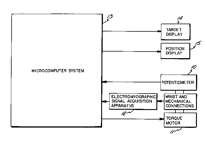
Figure 1 shows a block diagram of apparatus
used in practicing the present invention,
Figures 2A and 2B show data of three
dimensions obtained from use of the apparatus of
Figure 1 with a selected subject in a two dimensional
plot,
Figures 3A and 3B show data of three
dimensions obtained from use of the apparatus of
Figure 1 with a selected subject in a two dimensional
plot,
Figures 4A and 4B show data of three
dimensions obtained from use of the apparatus of
Figure 1 with a selected subject in a two dimensional
plot,
Figures 5A and 5B show data of three
dimensions obtained from use of the apparatus of
Figure 1 with a selected subject in a two dimensional
plot,
Figures 6A(i)-(iii) and 6B(i)-(iii) show
graphs of corresponding references for, and
corresponding averages of selected data obtained from,
the data used in the plots of Figures 2A and 2B
through 5A and 5B,
Figures 7A, 7B and 7C show comparative plots
of values of indices found for selected subjects
obtained from the use of the apparatus of Figure 1
with such subjects,
Figures 8A, 8B and 8C show comparative plots
of values of indices found for selected subjects
- 8 - 20 I q823
obtained from the use of the apparatus of Figure 1
with such subjects,
Figure 9 shows comparative plots of values of
an index found for selected subjects obtained from the
use of the apparatus of Figure 1 with such subjects,
and
Figure 10 shows comparative plots of values of
an index found for selected subjects obtained from the
use of the apparatus of Figure 1 with such subjects.
DETAILED DESCRIPTION OF THE PREFERRED EMBODIMENTS
Figure 1 shows a block diagram of a testing
arrangement used in practicing the present invention.
The subject of a test in this arrangement has his or
her dominant side forearm horizontally immobilized by
a bracing arrangement located close to the wrist but
leaving the location of the muscle bulk of the muscles
operating that wrist exposed so that electrodes for
acquiring electromyographic signals can be placed
thereon. The forearm of the subject is immobilized in
such a manner that the base of the thumb of the hand
of that forearm would be in an approximately superior
position on a vertical axis so as not to impede the
sliding of tendons or the contracting and lengthening
of the muscles operating the wrist.
The hand of such a subject is secured to a low
mass handle in a manner so as to keep that hand in a
position of a neutral grasp for operating purposes.
That handle is secured both to a potentiometer, 10,
and to a torque motor, 11, as indicated in Figure 1.
The handle connected to potentiometer 10 and torque
motor 11 is permitted to easily and conveniently
rotate about a vertically oriented axis, and to
receive torques about such an axis, with this vertical
axis being more or less collinear to the axis of
9 2r)l 9
rotation of the wrist in the position thereof
established as indicated above.
Electromyographic signal acquisition
apparatus, 12, of a well known kind, is used to
acquire the necessary electromyographic signals from
the muscles operating the wrist. The
electromyographic signals are sensed using circular
4.0 mm diameter silver-silver chloride transcutaneous
or surface electrodes placed over the major bulk of
two wrist operating muscles on either side of the
forearm, the flexor carpi ulnaris and the extensor
carpi radialis. Three such electrodes are provided on
each of these muscles, two sensing electrodes that are
6.0 to 10.0 cm apart longitudinally over the maximal
palpable bulk of the muscle with a reference electrode
placed between each of such sensing electrode pairs on
that muscle.
A microcomputer system, 13, is used to display
a moving target formed by a source of light that is
small with respect to the path dimensions, and which
follows a reciprocal positioning scheme in that the
target oscillates in position in a sinusoidal manner.
The subject being tested is to attempt to track this
target through moving the handle described above to
which his or her hand is attached to follow the
positional changes of that target.
Microcomputer system 13 also controls torque
motor 11 by selectively supplying current pulses
thereto each of which causes a corresponding impulsive
torque of a selected duration and amplitude to be
delivered from torque motor 11 to the test subject's
hand through the same handle indicated above to which
the hand of the subject of the testing is connected
during his or her tracking efforts. Such torque
2~l q823
-- 10 --
pulses, or torques, each force the wrist joint of that
subject for the hand connected to the handle to rotate
as that hand is forced toward either a flexion
position with the palm of the hand coming toward the
forearm or to an extension position with the back of
the hand coming toward the forearm.
A target display, 14, is shown to the subject
during testing under control of microcomputer 13 as a
horizontal bar display comprising 101 light emitting
diode elements set out in a linear array of
approximately 10.0 cm length. At typical viewing
distances for the subject and with typical target
rates of motion, the individual light emitting diode
elements appear subjectively fused into a line shape.
An impression of continuous target motion results when
successive elements are driven in sequence following
selected points in a sinusoidal position function at
the frequencies of oscillation, or position
reciprocation, used in the testing.
Microcomputer system 13 at the same time also
acquires data on actual wrist position from precision
potentiometer 10 for display so that the subject can
view his or her success in tracking the target. A
display, 15, similar to the one used to display the
target is used to show the subject the actual position
achieved by his or her hand rotating about his or her
wrist joint to move the handle to follow the target.
The subject under test attempts to match the two
displays by moving his or her hand about the wrist
joint in such a manner as to cause the actual position
indicated on display 15 to match that of the target
shown on display 14. In the sinusoid wave form
generated by microcomputer 13 to set the position of
the target in display 14, a zero amplitude value
2~1 ~823
-- 11 --
occurs at approximately the neutral position of the
wrist between extension and flexion, and the value of
the amplitude at soo and 270 on that sinusoid
represents maximum extension and maximum flexion,
respectively. Microcomputer 13 selectively generates
current pulses which, under certain conditions, are
delivered to torque motor 11 to cause it, as described
above, to provide corresponding impulsive torques at
its output to the handle to which the subject's hand
is attached to stretch the muscles being measured to
elicit a stretch reflex therefrom. Microcomputer 13
accomplishes this through use of a digital-to-analog
converter and suitable amplification to provide a
sufficient current pulse. The peak amplitude of the
torque step is in the range of 0.5 to 0.75
Newton-meters with a duration of approximately 250.0
ms. The direction of the torque delivered, whether
forcing the hand in a direction to cause greater
flexion or to cause greater extension when delivered
at selected times during tracking, i.e. at selected
phase points of the tracking sinusoid, is determined
on a random basis by microcomputer 13.
In practice, such impulsive torques are
provided to the hand of the subject being tested, if
at all, at only the 0/360 point (assuming the
remaining parts of the sinusoid to be repetitions of
its initial cycle rather considering it to be multiple
cycles of a constantly increasing angle) the 90
points, the 180 points and the 270 points of the
tracking sinusoid, and then only if the subject's hand
positi~n matches the computer generated target within
a specified error at those potential impulsive torque
deliverance phase points of the target position
sinusoid. Typical error limits would be that the hand
- 12 - 2~1 982 ~
angular position with respect to the forearm is within
3 of the target when within 100 ms from the selected
torque deliverance phase points in the target position
sinusoid. Failure of the subject to track within
these error limits causes microcomputer 13 to avoid
causing torque motor 11 to deliver an impulsive torque
and eliminates any data collected during that position
cycle to insure similar sinusoidal volitional tracking
behavior at the time of each such delivered torque
impulse.
In any event, at each of these potential
impulsive torque deliverance phase points,
microcomputer 13 not only randomly selects the
direction of any impulsive torque applied to the
subject's hand, but also on a random basis determines
whether any torque pulse will be delivered at all at
any one of these phase points at each occurrence
thereof during the target position cycles. Such non-
delivery of a torque impulse at such a phase point
means that is no stretching of the measured wrist
operating muscles so that no stretch reflex
electromyographic signal activity is present, and so
only volitional directive electromyographic signal
activity is in that instance available for measure.
The angular position of the subject's wrist,
and the electromyographic signals obtained by
apparatus 12 from the extensor and flexor muscles, are
acquired through an analog-to-digital converter
sampling the signals at a rate of 2,000 samples per
second which samples are then provided as digital
words of 12 bits each. The electromyographic signals
obtained from the electrodes are amplified in
apparatus 12 from 5,000 to 20,000 times before
conversion as is determined to be needed for a
- 13 - 2a 1 ~23
particular subject and the equipment of Figure 1. A
band-pass filter in that amplifier filters the analog
signals obtained from the electrodes at the wrist
before providing them to the analog-to-digital
converter therein, with the band-pass filter
characteristic having cutoff frequencies at 10 and
300 Hz.
Microcomputer system 13 in addition provides
for recording of the data obtained from the
electromyographic signal acquisition apparatus 12.
Further, handle and so angular position with respect
to its forearm data is similarly recorded thereby from
potentiometer 10. The signal processing of this data
in a manner to be described below can also be
accomplished by microcomputer 13 and the results
thereof stored in a similar manner.
A subject to be tested is instructed to track
the position of the target by moving the handle while
remaining relaxed and attempting to avoid any reaction
to the torque pulses except to continue to attempt to
track the target. The subject is to be discouraged
from active grasping of the handle to avoid causing
activation of the long finger flexor-extensor muscles
which would generate electromyographic signals that
could mix with those being measured in connection with
the wrist flexor and extensor muscles. A practice
period is provided ahead of time to the subject to
have that subject achieve a desired competence level
before beginning any testing. The subject then
typically performs two series of tests of ten
repetitions each. The results of these two series are
averaged by microcomputer 13 based on the data
supplied thereto from electromyographic signal
acquisition apparatus 12.
20 i ~323
- 14 -
In addition to the averaging of the two test
series, the data that is desired to be obtained are
the electromyographic signal samples which occur after
the successful tracking of the target position past
each of the potential impulsive torque deliverance
phase positions along the target position sinusoid in
each cycle, these again being the 0/360, 90, 180
and 270 phase points at which an impulse of torque
may, on a random basis, be delivered to the handle and
so to the hand of the subject. This electromyographic
signal data from the electrodes over the selected
wrist operating muscles indicated above, having any
amplifier offsets and the like removed, is collected
for 120 ms after the imposition of an impulsive
torque, or after the passing of such a phase point
without such an imposition. Such data collected is
digitally rectified so that it is of a single
polarity.
The resulting electromyographic signal sample
points for each such collection are grouped into 12
groups, each representing the points collected in a
10 ms interval of the entire 120 ms data collection
duration. The average signal value is found for the
signal samples in each of these groups. A further
averaging of these averages is taken for each such
collection of data over the number of repetitions
during testing of identical collection conditions.
That is, the 12 group time averaged values resulting
from a collection of data at each potential impulsive
torque deliverance phase point along the target
position sinusoid are averaged with the other
collections that occur at that phase point, averaging
those occurring there with an imposition of an
accompanying impulsive torque among themselves and
- - 15 - ~ nl 9 823
averaging those without such an accompaniment among
themselves.
Thus, electromyographic signal averages
representative of volitional directives to the muscles
involved are acquired at each potential impulsive
torque deliverance point along the target position
sinusoid for the averages of those electromyographic
signal portions which occurred in the absence of any
impulsive torque being delivered at those points.
Nixed reflex and volitional electromyographic signal
averages are acquired at each potential impulsive
torque deliverance point along the target position
sinusoid by averaging those electromyographic portions
which occurred when accompanied by the occurrence of
an impulsive torque. These mixed averages are
converted to essentially stretch reflex only
electromyographic signal averages by subtracting from
the former the averages representing the volitional
electromyographic averages previously described.
Alternatively, division could be used rather than
subtraction.
As a result, a volition matrix of 12 rows and
four columns is obtained from the volitional based
electromyographic signal averages and a similar reflex
matrix is obtained from the stretch reflex based
electromyographic signal averages for each subject
tested. Each of the 12 rows represents the average of
the rectified electromyographic signals for one of the
twelve 10.0 ms time intervals in the 120 ms duration
data collections following successful tracking through
each potential impulsive torque deliverance point.
Each of the columns represents one of the four
potential impulse torque deliverance phase points
- 2~') 1 9(~23
- 16 -
along the target position sinusoid cycle at whic~ e~
data collections were taken.
These two matrices, the volition
electromyographic data matrix and the reflex
electromyographic data matrix, contain the information
on the control directives provided to the muscles
involved in operating this wrist at the selected
points during the prescribed volitional movement, and
the information on the stretch reflex response of
those muscles at selected points in such movement.
They thus provide the basis for making a determination
of whether the modulation of the stretch reflex for
these muscles is properly coordinated with the
volitional directives thereto during contractions and
lengthenings thereof.
one way of presenting this data to an observer
is to provide a graphical representation to permit at
least qualitative analysis thereof, and this may be
done by eYrAn~ing these matrices to 36 row by 12
column matrices using inverse distance weighted linear
interpolation. The elements thus generated are used
to form closed contours (some closed by plot borders)
on a plane having cartesian axes with data collection
time duration (following successful target tracking
through potential impulsive torque deliverance points)
on one axis in milliseconds, and the target position
sinusoid cycle phase in degrees on the other axis.
Each contour in a plot is drawn by interpolation
between values provided from this ~Yp~n~ed matrix
through points having a common selected value of
electromyographic signal strength with each contour in
a plot having a different selected common value as its
basis. A first pair of such plots corresponding to a
tested individual are shown in Figures 2A and 2B.
20 1 9~23
- 17 -
Figures 2A and 2B show plots resulting from
the two reflex matrices obtained by testing two wrist
operating muscles as described above for a normal
subject not suffering from Parkinson's disease.
Figure 2A has time in milliseconds plotted along the
ordinate axis with zero representing the time at which
an impulsive torque was applied through the handle to
the hand of the subject at one of the potential
impulsive torque deliverance phase points in the
target position sinusoidal cycle. The phase of such
cycles is shown in degrees along the abscissa axis.
A vertical bar shading chart is shown to the right in
which the range of values of the electromyographic
signal averages for each shading type is given.
Figure 2A shows the measured electromyographic
stretch reflex averages of the above-noted flexor
wrist operating muscle involved from which data was
obtained during testing of the subject's wrist.
Repeating, the phase points of 0/360 and 180
represent the neutral point of the hand between
flexion and extension with respect to the wrist.
However, since the 90 phase point represents maximum
extension and the 270 phase point represents maximum
flexion of the wrist joint, the phase point 0/360
represents the wrist coming to the neutral position
after the completion of a maximum flexion so that hand
velocity and wrist angular rotation rate are at a
maximum in approaching the next full extension. On
the other hand, 180 represents the hand reaching a
neutral position with respect to the wrist after the
last extension and represents the point at which that
hand velocity and rotation rate of the wrist are
reaching a maximum in the next approach of the hand to
full flexion.
2nl~s23
- 18 -
As can be seen in Figure 2A, the signal
strength in the electromyographic signals is heavily
concentrated about the 180 phase point which is where
the flexor muscle is most rapidly contracting so as to
have the hand velocity and the wrist rotation rate to
reach a maximum in causing the hand to reach the next
full flexion position. Thus, the electromyographic
signals associated with the stretch reflex are clearly
happening at a time when they will aid the volitional
electromyographic signals which are directing the hand
to go to a full flexion position.
Figure 2B represents a plot of the same nature
as that of Figure 2A, but for the corresponding
extensor muscle of the same subject. As can be seen
here, electromyographic signal strength is strongly
concentrated about the 0/360 phase point where the
contracting of that muscle has the hand velocity and
the angular rotation rate of the wrist reaching a
maximum in causing the hand to next approach the full
extension position. Again, these signals are clearly
occurring in the proper phase to be able to have the
stretch reflex aid the volitional directives to move
the hand to a full flexion position.
Figures 3A and 3B, on the other hand, show the
results for a subject who suffers from Parkinson's
disease. Figure 3A shows that for the flexor muscle
the electromyographic signal strength, rather than
being concentrated at 180, is instead concentrated at
90 and somewhat at 270. Thus, the stretch reflex is
acting at points in time primarily when the hand has
taken either the maximum extension position or the
maximum flexion position rather than when the flexor
muscle is to be contracting at its maximum to cause
20 1 9823
-
-- 19 --
the hand to be driven toward its next maximum flexion
position.
As a result, there is significant
electromyographic signal strength due to the stretch
reflex occurring`in the wrong time with respect to the
volitional directives to be of aid in bringing the
hand to this next flexion position, and some of this
stretch reflex activity is clearly occurring where the
extensor muscle is to have its strongest contractions
and so is acting to brake the motion toward this next
maximum extension position rather than aiding the
reaching of it. Figure 3B, on the other hand, appears
much more like that of a normal person not suffering
from Parkinson's disease indicating that the extensor
muscle stretch reflex is still properly coordinated
with the volitional directives in moving the hand
toward its next maximum extension position. Thus, the
stretch reflex modulation is defective only with
respect to the flexor muscle.
Figure 4A and 4B represent the testing of
another subject with approximately the opposite
results with respect to the previous subject of
Figures 3A and 3B. Figure 4A shows that the
electromyographic signal strength is concentrated at
the 180 for the flexor muscle involved, just as it
should be for having the stretch reflex capabilities
of that muscle aid the volitional directives in
causing the hand to reach the next full flexion
position.
On the other hand, the extensor muscle
electromyographic signal strength is also concentrated
near 180 with the result that the stretch reflex of
this muscle is acting to brake the motion of the hand
by acting against the flexor muscle in having the hand
20 1 9~2s
- 20 -
attempt to reach full flexion while failing to aid the
volitional directives to the extensor muscle to reach
full extension. Clearly here, there is a defect in
the stretch reflex of the extensor muscle.
Figures 5A and 5B show the results for a
subject who has defects in the stretch reflex of both
the flexor and the extensor muscles being measured in
connection with testing that subject's wrist joint
response in following the target sinusoidal position
path. As can be seen in Figure 5A, the
electromyographic signal strength is concentrated to
a substantial degree at the 0/360 phase point
clearly showing that the stretch reflex of the flexor
muscle is being activated at such times as to brake
the activity of the extensor muscle in reaching the
next full extension position for the hand. Here,
though, there is some aid being provided the flexor
muscle to reach the next full flexion position of the
hand. But this effort is being braked by the extensor
muscle as shown in Figure 5B where the
electromyographic signal data is clearly concentrated
about the 180 phase point. Relatively little
electromyographic signal strength occurs at the
0/360 phase point to suggest that the stretch reflex
of this extensor muscle is aiding the volitional
directives urging the hand reach the next full
extension position.
If plots of the kind shown in Figures 2
through 5 are averaged along the time axis on the
ordinates therein, graphs of the kind shown in some of
Figures 6A(i-iii) and 6B(i-iii) result. Figures 6A(i)
and 6B(i) show just for reference the repeated
sinusoidal path cycle followed by the target which is
to be tracked by the subject under test. The dashed
- 21 - 2 0 1 ~ `~,23
line pairs along the phase axis, or abscissa,
represent the required successful tracking ranges
about potential impulsive torque deliverance phase
points in which potential impulsive torque
deliverances can occur. The 90 point and the 270
points again represent the maximum extension position
of the hand with respect to the forearm and the
maximum flexion position of the hand with respect to
the forearm, respectively.
Figure 6A(ii) shows a graph which is the
result of such a time averaging of the previous kinds
of plots in Figures 2A and 2B through 5A and 5B. The
solid line shows a typical graph found for a normal
person. The dashed line graph shows results for
persons suffering from Parkinson's disease, and
clearly shows that the reflex electromyographic signal
strength is shifted leftward to different phase points
and so to a different time with respect to that of a
normal person.
Figure 6A(iii) shows the result obtained from
the volitional matrix resulting from the tests. As can
be seen, for a normal person, the stretch reflex
electromyographic signal strength comes just ahead of
the phase points where the volitional
electromyographic signal strength is concentrated and
so aids the volitional movement. For a sufferer of
Parkinson's ~;se~ce, however, the stretch reflex
electromyographic signal strength is concentrated well
before the concentration of the volitional
electromyographic signal strength and, as can be seen
in Figure 6B(ii), is reaching peaks just when the
reflex signal strength for the opposite extensor
muscle should be at a peak thus causing braking of the
movement to be forced by that extensor muscle.
- 22 - 2 0l 9 a2 3
The situation with respect to the extensor
muscle shown in Figure 6B(ii) for the stretch reflex
thereof and Figure 6B(iii) for the volitional
directives to that muscle gives a similar result.
Again, the solid line in the stretch reflex graph of
Figure 6B(ii) is for a normal person with the dashed
line being that for a sufferer from Parkinson's
disease. Once again, the stretch reflex signal
strength occurs at a different phase point and so at
a different time for one suffering from Parkinson's
disease than it does for a normal person. Again, this
leads to a time displacement with respect to the
volitional signal strength concentration and results
in braking activity occurring in the extensor muscle
if there has been proper movement activity initiated
by the flexor muscle.
This situation of normal persons' outcomes
from this testing versus outcomes of sufferers from
Parkinson's dice~e for essentially the same testing
can be made quantitative by forming suitable indices
representing the conditions just described. These
indices can be based on the electromyographic signal
strength occurring in the 40 to 120 ms portion of the
0 to 120 ms data collection range in which data is
collected after the target has been suitably closely
tracked through the potential impulsive torque
deliverance points in the target position sinusoidal
path. Time averages over this time duration have been
found sufficient to cover essentially all of the
significant electromyographic signal amplitudes
occurring in the modulation of the stretch reflex and
in the volitional directives.
The indices are based, however, on only the
0/360 potential impulsive torque deliverance point
- 23 - 2 ~ 1 q 8 2 3
and the 180 potential impulsive torque deliverance
point. Time averages from these two phase points were
chosen because they represent the maximum velocity of
the tracking movement in approaching the next full
extension position of the hand and in approaching the
next full flexion position of the hand, respectively.
These are the points when one or the other of the
extensor muscle and the flexor muscle should be making
their maximum contracting effort while the other
should be making little contracting effort but,
rather, lengthening.
Thus, at the 0/360 phase point, the extensor
muscle would be providing maximum assistance in its
stretch reflex to the volitional directives while the
flexor muscle should be leng~hen;ng so that any
contracting effort by this latter muscle represents a
braking of the motion being caused by the extensor
muscle. Similarly, at the 180 phase point, the flexor
muscle should be providing its greatest assistance to
the volitional directive of forcing the hand to its
next full extension, and the extensor muscle should be
lengthening so that any electromyographic signals
indication contraction thereof will act to brake the
motion being caused by the flexor muscle.
A first suitable index is the reflex log
assistive/braking ratio which is the logarithm to the
base ten of the ratio of (a) the average stretch
reflex electromyographic signal strength in the 40 to
120 ms duration data collections described above at
the cyclic maximum contracting effort phase point for
the muscle involved (or the maximum hand velocity
point), to (b) the average stretch reflex
electromyographic signal strength for the same time
range taken at that tracking phase point in which the
,,
- 24 - 2 ~ 1 q 8 2 3
hand is at maximum velocity during the cyclic
lengthening of that same muscle due to the contracting
of the opposite muscle in an agonist-antagonist pair.
For the extensor muscle involved, this index
would be the base ten logarithm of the ratio of (a)
the average electromyographic signal strength
occurring at the 0/360 phase point over 40 to 120 ms
in the reflex matrix for that muscle, to (b) the
average electromyographic signal strength occurring at
the 180 phase point in that matrix (this data could
be taken from any of the figure "B" plots found in any
of Figures 2B through 6B). In this ratio, the
numerator value could be either of the values marked
"N" in Figure 6B(ii) (depending on which of the two
tested subjects represented by the two curves shown,
one normal and one suffering from Parkinson's disease,
was of interest), and the denominator value could be
either of the values marked "D" in that figure.
For the corresponding flexor muscle, the
reverse will be true so that the index will be the
base ten logarithm of the ratio of (a) the time
average for 40 to 120 ms of the electromyographic
signal data occurring at the 180 phase point in the
reflex matrix for that muscle, to (b) the time average
over that same time range of the electromyographic
signal data occurring at the 0/360 phase point in
that matrix (this data could be taken from any of the
"A" plots of Figures 2A through 5A). In this ratio,
the numerator value could be either of the values
marked "N" in Figure 6A(ii) (again depending on which
subject was of interest), and the denominator value
could be either of the values marked "D" in that
figure.
2 ~ 2 3
- 25 -
An analogous volitional electromyographic
signal index is the volitional log assistive/braking
ratio which is the base 10 logarithm of the ratio of
(a) the time average over the same 40-120 ms time
duration of the electromyographic signal strength for
volitional only electromyographic signals at the point
of maximum velocity of the hand being forced by the
muscle involved during its contraction, to (b) the
time averaged volition only electromyographic signal
strength at the phase point where the hand is at
maximum velocity due to the contraction of the
opposite muscle leading to the lengthening of the
muscle involved. As indicated above, volition only
electromyographic signal data is that data obtained in
the testing described above forming the pertinent
volition matrix. The same procedure is followed in
forming this index involving volition for the extensor
and flexor muscles involved as was followed above
using the reflex matrix for these muscles.
Although no plots have been presented of the
type shown in Figures 2A and 2B through 5A and 5B for
volition only electromyographic data, similar plots
can be constructed from such data as is found in the
corresponding volition matrix and so the information
for this volition index could be found from such
plots. This ratio of this volition index could, for
the subject represented, be formed from the data
values found in Figures 6A(iii) and 6B(iii) for the
flexor and extensor muscles measured, respectively,
using the values marked "N" for numerators and values
marked "D" for denominators.
The higher the value of one of these log
ratios the greater the increase in the stretch reflex
assisting the volitional directives or the greater the
- 2f~ 1 9823
- 26 -
decrease in braking the motion caused by the opposite
muscle involved in operating the joint. (The
logarithm of the ratio found is used to linearize the
scale.) Graphs of such reflex log assistive/braking
ratios determined for a group of normal persons and a
group of sufferers of Parkinson's disease are shown in
Figures 7A and 7B for the flexor and extensor muscles
thereof under test in those subjects, respectively.
As can be seen, the ratios cluster about lower values
for sufferers of Parkinson's ~ice~ in the column
labeled "P" than they do for normal persons in the
column labeled "N". A worst case selection of the
worst of the ratios for each of subject under test
gives the results shown in Figure 7C. Clearly,
selecting the worst of these ratios for each of the
people involved increases the tendency of the ratios
to differ in clustering about values for normal
persons versus those suffering from Parkinson's
disease.
Similar graphs of volitional log
assistive/braking ratios determined for these same
subjects are shown in Figures 8A, 8B and 8C for ratios
based on volition only electromyographic data. Little
difference occurs, if any, between normal persons and
those suffering from Parkinson's disease thus
confirming that, for Parkinson's disease suffers,
stretch reflex defects are involved to a more
significant degree for these test subjects than are
any volitional defects. The test subjects which are
sufferers of Parkinson's disease in all of these plots
are confirmed to be so suffering through several other
kinds of clinical tests.
Two further indices can be found for each of
the muscles involved which tend to isolate the
- 27 - 2~ 1 9823
assistive aspects and the braking aspects of the
electromyographic signals. The log assistive/mean
ratio is the base 10 logarithm ratio of (a) the time
average over the same time of the stretch reflex
electromyographic signal strength taken at the phase
point at which the hand has maximum velocity due to
the contraction of the muscle involved, to (b) the
time average of the electromyographic signal strength
at both the phase point at which the hand achieves
maximum velocity due to the contraction of the muscle
involved and at the phase point at which the hand, due
to the contracting of the opposite muscle operating
the joint, achieves maximum velocity leading to the
muscle involved lengthening, and at the maximum
flexion and extension phase points. The log
braking/mean ratio is the base 10 logarithm, of the
ratio of (a) the time averaged electromyographic
signal data taken at the phase point where the hand
has the maximum velocity, due to the contraction of
the opposite muscle operating the joint, leading to
the muscle involved lengthening, to (b) the time
average of electromyographic signal strength at both
the phase point at which the hand achieves maximum
velocity due to the contraction of the muscle involved
and at the phase point at which the hand, due to the
opposite muscle operating the joint, achieves maximum
velocity, and at the maximum flexion and extension
points.
Finally, there is the joint actions of the
agonist and antagonist muscles, or the flexor and
extensor muscles being measured in connection with the
wrist test described above, which must be considered
insofar as their being co-activated. Two further
indices for giving an indication of this are based on
2û 1 9823
- 28 -
the reflex matrix described above and the volition
matrix described above for each of these muscles.
These indices were constructed by first normalizing
the elements of each matrix for each muscle by the
mean of that matrix and then replacing resulting
elements which fall below a threshold value such as
0.25 by zero. Corresponding elements from the reflex
matrices were compared with the smaller element in
each such correspondence being divided by the larger
element to form a new matrix with any division by zero
situations arising leading to a zero inserted in the
new matrix. The elements of the new matrix associated
with stretch reflex data were then summed to yield a
single value, the reflex electromyographic co-
activation indicator, which increases with increasesin joint reflex electromyographic signal strengths
occurring in the flexor and extensor muscles.
Similar steps were taken with the normalized
and substituted volitional matrices for these two
muscles to define the volitional electromyographic
signal co-activation indicator.
These indices are shown for again the same
group of normal subjects and a group of sufferers from
Parkinson's disease in Figures 9 and 10. Figure 9,
representing a joint indicator based on the stretch
reflex data matrices, shows a relatively low value
grouping for normal persons, but a much higher value
for sufferers from Parkinson's ~ice~se although there
is some overlap. Figure 10, on the other hand, based
on volitional data matrices, shows there is no
significant difference in groupings between normal
persons and those suffering from Parkinson's disease.
Thus, again, these data show that stretch reflex
deficiencies are much more closely associated with
2~1 ~823
- 29 -
sufferers of Parkinson's disease than are any
volitional directive deficiencies.
Although the present invention has been
described with reference to preferred embodiments,
workers skilled in the art will recognize that changes
may be made in form and detail without departing from
the spirit and scope of the invention.