Note: Descriptions are shown in the official language in which they were submitted.
~2~3~
.
DROPl)UT-FREE CENTER POINT FILL
METHOD FOR DISPLAYING CHARACTERS
FIELD OF THE INVENl'ION
In modern computer systems, it is often desireable to
S print or display characters in v rious sizes on paper, film or a
computer screen. When the 6ize of the character i5 laxge rela-
tive to the resolution of the display or print device, it it
relatively easy to choose which picture elements or pixel6 should
by printed or displayed in order to make a readable character.
However, when the size of the character is small in relation to
the resolution of the display, it is much more difficult to
choose which pixels to display in order to make the character as
dîstinct and recognizable as possible. The current invention
relatas to an improved method of legibly displaying characters at
low resolution.
BACRGROIJND OF THE INVENTION
Traditionally, characters have been printed using metal
type which allows very detailed rendering of a character, includ-
ing subtle curves and very fine lines. In modern computer de-
vices, characters are defined on raster devices such as videodisplay terminal or by using a multi-pin print head. Character
can be printed on a surface or displayed on a video screen as a
series of dot which are printed or turned on in order to approx-
imate a closely as possible the ideal shape of the character.
When characters are small enough relative to the resolution of
D-914 Dropout-Free Center Point Fill - 1 -
~,~2~3~
the di6play deYice, choosing which pixels should be displayed to
accurately represent the character becomes more complex than when
the character ts large. A typical video mon:itor can display
about 72 pixels per inch. At thls resolution it is difficult to
display legibly most type faces smaller than about twenty pixels
all.
An ideal representation of the character is usually
defined in "character space" at very high resolution as one or
more areas bounded by an outline or path. A character consists
of one or more continuous black areas. For instance the letter
"O" consists of a single closed loop, the letter "d" consi6ts of
a loop connected to a line and the letter "i" consists ess0n-
tially of a dot a short distance way from a line which may have
additional details such as serifs. One way of de3cribing a char-
acter involves defining an outline of the outer edge of eachconti~uous black portion of the character and then filling that
outline to display the character. Since characters are usually
printed in dark ink on a light background, one can describe
filled areas us black but one skilled in the art will recognize
that charac~er6 which are light on a dark background, commonly
used in video displays are also within the teachings of this
invention. This path can be represented as a sequential series
of curves and/or linear line segments called edges. If a black
area has interior white spaces as, for instance, in the letter
UO", each interior white area can also be defined by a path
consisting of a series of edges.
D-914 Dropout Free Center Point Fill - 2 -
~2~
When tracing or displaying such a character, it is
generally useful to trace the edges in a consistent direction,
either clockwise or counter-clockwise. If edges of an outside
path are traced in the counter-clockwise direction, then the area
S to the left of that edge will always be black and the area to the
right will always be white. If the path is traced in the clock-
wise direction, the black area will be on the right of the edge.
unclosed white areaæ should be traced in the direction opposite
to the exterior path so that the black area is on the same rela-
tive side of the edge.
When a character i8 displayed on a raster device, thosepixels which fall within the black area of the character should
be displayed, that i8 they should be printed on a surface or
turned on for a video display. At high resolution or when the
character it very large, multiple pixels may fall within each
black area and the character can be displayed in great detail.
When the character is reduced to a small size, however, or the
resolution of the device is limited, certain black areas may no
longer cover multiple pixels and in fact may cover only a frac-
tion of a pixel. Displaying small characters on a device oflimited resolution has been a persistent problem in the past.
This is illustrated in the figures by a character on an BxlO
matrix. In Figure 1 the outline of the character "S" is illus-
trated as filled at very high resolution. The raster display,
however can only turn on or off entîre pixels.
D-914 Dropout-Free Center Point Fill - 3 -
One prior approach to this problem is the center point
fill method, illustrated in Figure 2. A pixel it displayed only
if the center of that pixel falls within or on the boundaries of
a black area, illustrated by pixels 40 - 44. Where only a limit
ed number of pixels are available to display the character, there
are gap5 or dropouts 50 - 52 in the black areas 80 that it may ye
difficult to recognize the character. An alternative way of dis-
playing the character, called area fill, i6 to turn on all pixels
which intersect or fall within the outline of the character. The
result, shown in Figure 3, i8 that too many pixels are turned on,
leading to blobs which also make the character difficult to
recognize. At higher resolution both of these methods work
successfully but at low resolution characters become difficult to
recognize.
One object of this invention is to improve the legibility
of characters displayed at low resolution by turning on those
pixel in which the center falls in or on the edge of a black
area and also turning on enough additional pixels to make the
character recognizable. Another object of this invention i6 to
minimize dropout caused by a thin character stem going through 8
pixel row or column without including a pixel center.
Another object of this invention is to properly display a
pointed character feature such as the bottom of a "V." This is
important for cases like the base of a "V", where the bottom
pixel must be turned on or the character will appear to float off
the baseline.
D-914 Dropout-Free Center Point Fill - 4 _
~2~
BRIEF DESCRIPTION OF THE DRAWINGS
Figure 1 illustrates the 6uperimposition of the outline
of a character displayed at very high resolution on a low redo-
lution pixel matrix.
Figure 2 illu6trates the some character outline displayed
by low resolution pixel using the center point fill method of
the prior art
Figure 3 illu~trate~ the tame character on the 8am~ pixel
matrix displayed using the area fill method of the prior art.
Figure 4 illustrates the same character outline on the
tame pixel matrix displayed using the method of the present
invention.
Figures 5A and SB illustrate detail6 of the present
invention.
Figures PA - 6C illustrate details of displaying corners
in figures.
Figure 7 illustrates a figure with multiple edges and
enclosed black and white 6paces.
Figure 8 illustrates the detail-oriented method of
correcting dropout.
SUMMARY OF THE INVENTION
Charactsrs can be displayed with improved legibility at
relatively low resolution by modifying the center point fill
method and displaying additional pixel as nèeded to maintain
connectivity and avold dropout problem. Additlonal pixels are
D-914 Dropout-Free Center Point 5 _
2~2~31~
turned on as needed where a black 6ection of the character cros-
ses the line between two adjacent horizontal or vertical pixel
center6. Such lines will be referred to as ~midlines. One could
alto practice the present invention using reference point or
regions within the pixel other than the center. If the inter-
section of a black section of a character with a midline it
entirely within one pixel which i8 not otherwi e turned on then
that pixel is turned on. If a black section of a character
crosses between two such adjacent pixel reference points in part
of both pixels and if neither pixel is already on, the pixel
having more of the black section, mea5ured along the line between
pixel centers (or other reference points is turned on.
DETAILED DESCRIPTION OF THE INVENTION
A character can be represented by a series of filled
areas which contrast with the background. For convenience, the
filled areas will be referred to a6 black areas, as in ink
printed on a page, but the filled area can also be light on a
dark background, as in a typical video display. Pixels to be
displayed can be considered as turned on versus turned of.
the outline of each black area can be defined by
closed path consisting of seguential series of curves or linaar
line segmsnts called edges. The interior of each black area can
be distinguished from the background by traversing the outline of
the character in a clockwise or counter-clockwise direction and
filling or turning on of those pixels which are part ox the black
D-914 Dropout-Free Center Point Fill - b -
2~2~3~
area. In the ollowing description the outline of the character
is assumed to be oriented in the counter-clQckwise direction; the
left wide of each edge is part of the character and the right
wide of the edge is background. As described above character6
which have enclosed white spaces 6uch as thy character ~0" will
have at least one additional path consisting of a ~eri0~ of edges
to define each enclosed space. An interior path 6hould be trav-
ersed in the direction opposite to the outer path. A character
may contain more than one black area such as the letter n i n or
many oriental characters. Once a path or series of paths it
defined for a character, that path can, for example, be stored in
computer memory and can be used for generating chaxacters of
arbitrary size.
To display a character in a defined pixel area, often
referred to as display space, the outline of the character must
first be scaled and placed within a pixel grid by method well
known to those 6killed in the art. According to well-known
methods generally known 88 "center-point filln, pixels 40, 41,
42, having center 10, 11 and 65 respectively, which fall on or
within the outlive of the character are selected and displayed.
See Fig. 2. When the resolution of the display device iB low
enough relative to character size, certain portions of the
character will not include pixel centers and therefore will no
longer be displayed, Jo the legibility of the character will
decrease. In Figure 2, for example, certain areag 40 - 44 of the
character "So are properly displayed but pixels such as 50 - 52
D-914 Dropout-Free Center Point Fill _ 7 _
contain areas of the character which do not happen to include a
pixel center and thus are not displayed, making the character
less legible.
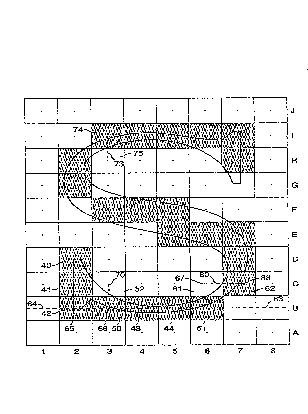
One method of practiciny the pxesent invsnt~on i5
illustrated in Figure 4. The pixels were tested sequentially,
starting for example with the pixels in row numbered 1, 2, 3,
etc. in order, followed by pixels in row B starting with number 1
followed by the pixels in row C starting with number 1, and Jo
forth. Pixels were processed by carrying out the following steps
for each row.
Where the center point of a pixQl such as pixels 42, 43
or 44 fell within a black area of a character, that pixel way
turned on. Within each horizontal pixel row, points were iden
tified where edges cros6ed the horizontal midline such as 63
through the pixel centers, including 64, 65 and 66. where two
consecutive edge crossings occurred between two adjacent pixel
center such as 67 and 68 such that a blacX section crossed a
midline, e.g. 60, the following proximity text was performed.
The same test was used for horizontal or vertical midline/
character intersections. Compare the examples of edges inter-
secting horizontal midlines in pixel6 61, 62 and 91, 92 of
Figs. 5A and 5B, with edges intersectinq vertical midlines in
pixels 50, 52 and 74, 7~ of Fig. 4. If the black section inter-
sected a midline entirely within one pixel, such as pixel 62 in
Fix. SA or pixel 74 in Fig. 4, that pixel was turned on. If the
black section crossed a midline, e.g. 95 in Figure SB, in parts
D-914 Dropout-Free Center Point Fill - 8 -
2 3
of two adjacent pixels, e.g. 91 and 92, and neither pixel was
already on, the pixel which contained the greatest length of
black section along the midline was turned on. One simple way Jo
select that pixel was to determine the pixel whose center was
closer to an edge/midline intersection, e.g. pixel 91 in Fig. 5B
and pixel 50 in Fix. 4. If the black Rection crossed the midline
equidistant from both pixel centers and neither pixel was on, one
pixel was turned on arbitrarily. One methoct of resolving the
arbitration is to always turn on the first of the two pixel
along the scan line. Another method of resolving the arbitration
i6 to alternatively turn on the first and then the second pixel
each time an arbitration is required. Other arbitration schemes
are well known to those skilled in the art.
Another way to select pixels which include black sections
that cros6 vertical midlines is as follows. Where edge crossed
a vertical midline of a pixel not already on anywhere in the row,
pair of flag was jet for each such cro6sing indicating whether
the crossing was in the top or the bottom of the pixel and
whether the edge was oriented left to right or right to left as
it crossed that vertical midline. Multiple pair of flags were
jet as needed for each 6uch crossingO Aftar the row way scanned
according to the method in the previous paragraph and flags were
set, the flags were checked for each pixel in that row which was
not already on. If a pixel had only a top, left-to-right or one
top, left-to-right plus a bottom, right-to-left crossing, the
flags were stored until the next scan llne was analyzed to decide
D-914 Dropcut~Fxee Center Point Fill - 9 _
2a2(~3~
whether or not to turn that pixel on. If a pixel had only a
bottom, right to-left or one bottom, right-to-left plus a top
left-to-right nosing and the pixel below was already on, then
the present pixel way left off, but if the pixel below was of
and had flags set indicating only a top left-to-right crossing or
one top left-to-right plus a bottom, right-to-lef crossing, then
tne present pixel or the pixel below was turned on according to
the proximity test detailed above. If the current pixel had any
other flags or combination of flags set, then it was turned on.
AfteL each row was analyzed according to the foregoing method,
the pixel map could be displayed or could be stored for future
display. Yor example, pixel 50 in Figure 4 had a top left-to-
right crossing, Jo appropriate flag5 were set. Pixel 52 included
a bottom right-to-left crossing but pixel 50 way not turned on
according to the center point fill test. Applying the proximity
test, the edge/midline intersection in pixel 50 was closer to the
pixel center than the edge/mudline intersection in pixel 52, 60
pixel 50 way turned on.
The method described above will give generally accurate
character bit-maps, but certain shapes will cause an inappropri-
ate pixel to be turned on. This i6 illustrated in Figure 6 by a
path which could be part of the letter ~Z" or the number "7.~
Pixels ~3 - H6 were turned on in accordance with the center-fill
testO Pixels I3 - I6 were not turned on since each had a flag
for only a bottom right-to-left crossing and the pixel below was
already on. Pixel I7 contained a black section which crossed the
D-314 Dropout-Free Csnter joint Fill - 10 -
2~31 6
vertical midline between pixels I7 and ~7 but was sntirely within
I7, Jo I7 was turned on. The character would, however, be more
legible if I7 was not turned on. Note that the result would be
better if the path croR~ed the I7 - H7 midline with one edge in
H7 that was farther from the center of ~7 than the edge in I7 was
from the center of I7.
Such artifacts wore eliminated by the following proce-
dure. Whenever, during the principle rasteriæation, a deci6ion
was made to activat or not activate a pixel according to the
proximity test, the resulting decision was stored a6 a proximity-
pixel pair con6i6ting of the selected pixel and the alternate
pixel. The alternate pixel was neces6arily horizontally or
vertically adiacent to the 6elected pixel. After the entire bit-
map had been scanned, each proxLmity-pixel pair way examined for
the following pattern, two examples of which are illustrated in
Figure ~B and 6C. Starting from the selected proximity pixel, if
a corner pixel adjacent to the alternate pixel and immediately
diagonal to the selected pixel was on, if the three pixels
horizontally and vertically adjacent to the selected pixel (other
than the alternate pixel) were either off or outside the pixel
grid and the three pixel diagonally adjacent to the 6elected
pixel (other than the corner pixel) were either off or out6ide
the pixel grid, then the 6elected pixel was determined to by
incorrectly chosen. In this casa, thy selected pixel was turned
off and the alternate pixel was turned on.
D-914 D~opout-Free Center Point Fill - 11 -
2~ 3~
It it possible to describe or outline some character
with a path which crosses itself one or more times. The five
pointed star shown in Figure 7 it one such example. If a row of
pixel such as Row 100 is scanned from 101 - 110, pixels inter-
sect the five edges 111 - llS of the five pointed star. accord-
ing to the method dessribed above, pixels 103 and 104 are between
edges 113, 114 and 111 and therefore shouid be displayed. Pixel
108 is between edges 112, 113 and 115 and should also be dis
played. Pixels 105, 106 and 107 should also be displayed because
they are to the left o$ edges 111 and 115. Pixels 126, 127 and
128, however, are also between edges 111 and 115 but should not
be displayed.
Two well known methods of displaying complex figures such
as this are the ~ven-odd method or the winding number method. To
best illustrate the invention, the following discussion will
illustrate its use with the winding number method using that
method where an edge crosses a horizontal or vertical reference
line, th0 direction of the path should be stored. According ko
the winding number method, for each crossing of a certain direc-
tion, for instance, downward, a winding counter can be increment-
ed and for each crossing in the opposite direction, up in this
example, the winding counter ifi decremented. In scanning line
100, where edge 113 cros6es pixel 102 the winding counter is
increased by 1, where edge lll crosses pixel 104 the winding
counter is increased again, where edge llS cr~s6es pixel 107 the
winding counter is decreased by 1 and where edge 112 crosses
D-914 Dropout-Free Center Point Fill - 12 -
2~ ?~
pixel 109, the winding counter is again decreased. For every
pixel between edges where the winding number is non-zero, that
pixel should be displayed. Row 120 gives an example where the
winding number increases to 1 in pixel 124 and decreases to zero
in pixel i25, increase again to 1 in pixel 129 and decrease6 to
Nero in that same pixel. Since the winding number it Nero for
pixels 126, 127 and 128, those pixel are left off. This tort of
situation occurs in many characters, for example the letter "B.~
One skilled in the art will recognize that the method of
this invention can be practiced by 6canning the pixel rows ver-
tically rather than horizontally and making appropriate modifi-
cations in the method. One skilled in the art can alto practice
a variation of the method of this invention wherein horizontal
rows of pixels are scanned to determine where edges cross the
horizontal midline of the row, turning on those pixels having
centers included in the interval between two consecutive edge
cros6ings 6uch that those centers are either on an edge or within
a black section of the character and al60 turning on those pixels
having a black section between two horizontal pixel center
according to the proximity test. Each column of pixels should
then be scanned, to determine where edges cross the vertical
midline of the column, turning on those pixels having center6
included in the interval between two consecutive edge crossings
such that those centers are either on an edge or within a black
2S section of the character and also turning on those pixels having
D-914 Dropout-Free Center Point Fill - 13 -
h 0 2
a black ection between two vertical pixel centers according to
the proximity test.
Another variation that can be practiced by those skilled
in the art is to first do a normal center point fill, and then
6troke the skeleton of the character u6ing a line drawing algo-
rithm. One method of deriving a character skeleton ifi descried
by I. Montanaxi, continuous Skeletons from Digitized Image6, n
Journal of the Association for Computinq MachinerY, 16(4~: 534-
54g, October 1969. Once the ~Xeleton is determined, wherever the
skeleton passes through a horizontal or vertical midline of a
pixel which i6 not already on, according to the center point fill
algorithm, the pixel should be turned on.
nother variation of this invention i6 useful when the
computer program is not required to run quickly and it is desired
l to choose the best possible pixel arrangement to represent the
character. This detail-oriented version of the algorithm de-
scribed above was divided into two parts that roughly corres-
ponded to the two parts of the previously mentioned algorithm a)
while determining certain character attributes doing a normal
center point fill, and b) turning on extra pixel6 to void drop-
out.
The first part of this detail-oriented method included
examining various properties of each pixel beyond just whether or
not it center was within the outline to determine if it should
be turned on or not. These properties included 1) the area ox
the pixel inside the outline, 2) whether any part of the outline
D-914 Dropout-Free Center Point Fill - 14 -
~2~3~6
pausing through the pixel realized local maxima or local minima
in either the or coordinates, 3) whether any part of the
outline passing through the pixel had any sharp corners and 4)
whether the pixel was known to lie on the base line, capital
height line or X-height line for characters of the font being
considered. All of the above guantities were given numeric
values which were then considered independently. If any of these
guantities exceeded a certain threshold the pixel was turned on.
Fur example, if part of character was within a pixel but did not
include the pixel center, if the occupied area was greater than
approximately 60%, that pixel way turned on. If any part of the
character outline realized a local vertical minimum in the lower
half of a pixel or a local vertical maximum in the upper half of
thy pixel, that pixel was turned on. Horizontal maxima and
minima were treated similarly. If an outline passing through a
pixel had any sharp corners, that is the outline formed an angle
sharper than 90 degrees, then a line bisecting that angle was
drawn to the closest pixel edge. A sharpness factor was calcu-
lated thus: 90 degrees minus the actual angle times a constant
(approximately 1~100). If the sum of the sharpness factor and
the length of the bisecting line was greater than one~half a
pixel edge length, that pixel was turned on. finally, if a pixel
was known to lie on the base line, capital height line or x-
heiqht line, each of the preceding three factors were treated as
more Eignificant, that i8 if the pixel wa6 on one of these lines
and if the included area way approximately 50~ or more, if a
D-914 Dropout-Free Center Point Fill 15 -
~203~
local minimum was below only about .55 pixel units or if the
corner parameter was less about .45, then the pixel was turned
onO
The purposes of the four criteria listed above are: 1) to
turn on pixels that are mostly covered by the outline even though
their center may not be covered, 2) o maze sure that curved
parts of the character reach a predictable size in their horizon-
tal and vertical directions and will thexeby be consistent with
other characters with similar shapes, 3) to insure that if the
outline has sharp corners, which often are part of character fea-
tures important for recognition of that character, that pixels
will be turned on to represent these corners, and 4) to be sure
that the various characters of a font all share the am bate
line, capital height and X-height.
Dropout problems may till remain after doing the first
part of the detail-oriented method, as with the center point fill
method of the prior art. The 6econd part of this algorithm cor-
rected the dropout problems by considering all parts of the
original character 6hape that were not in the bit map as created
at this stage. This process iB illustrated in Figure 8. The
various parts such as 140-149 of the or;ginal continuous char-
acter shape not within a displayed pixel were identified, and
divided by the pixel grid into pixel sub-pieces. For each tub-
piece, S, a distance number was computed telling the minimum
number of other pixel sub-pieces that must be traversed to get to
a pixel that has been turned onl including the pixel sub-piece
D-914 Dropout-Free Center Point Fill - 16
2~2~
itself. In this example, adjacent is used to mean two pixels
intersect on an edge or a corner. For example, pixel sub-piece
144 is adjacent to a di6played pixel that should be connected to
discontinuou6 pixel 160 Jo its distance number i8 one, but tub-
pieces 146 and 147 are one pixel removed from di6played pixel
160 or 161 Jo their distance number is two. Pixels containing
sub-pieces are then turned on as nscessary to make the figure
continuous.
If displayed portions A & B of the character should have
been connected but intervening pixels were not displayed, a list
of pixels giving the shortest connecting path of sub-piece pixels
was determined by the following method. Among the pixel tub-
pieces touchinq group A, the sub-piece with the largest area way
selected. The corresponding pixel necessarily had a distance
number of 1, relative to A. Starting from the selected pixel
sub-piece, each adjacent pixel sub-piece having a distance number
greater by one was tested and the pixel containing the largest
such sub-piece was selected. This process was repeated until the
adjacent pixel8 had only decreasing distance numbers. At that
point, the criteria for selection of the next pixel sub-piece was
modified by requiring that the distance number of the next pixel
in the list went down by one instead of up. Pixels already in
the list were not considered. The list was complete when a
pixel was added that touched the second group, B. Once the list
was completed, the pixel containing each piece in the list was
turned on. For example, pixels 161 and 160 should have been
D-914 Dropout-Free Center Point Fill - 17 -
2a~
connected but wexe not connected by the first part ox the method.
Starting from pixel 160, pixels 158 and 159 were ad~acen~ to
pixel 160 but pixel 159 included a larger sub-piece 14g. where-
fore, 159 way the first pixel on the ~iBt. Continuing from lS9,
156 and 157 each had a distance number of 2 but 156 included the
greater amount of character tub piece area, so pixel 156 was
added to the list. There were no sub-piece~ adjacent to 156 that
had a distance number greater than 2 and 157 was already in the
lit, BO it was ignored. Continuing from pixel 156, 155 and 154
each contained a portion of the character having the next lower
distance nun~er, 1. Pixel 154 was 6elected because it included
the greater character sub~piece area. The list comprising 159 t
156 and 154 gave a connected path hetween pixels 160 and 161.
One advantage of this method for correcting dropout i6
that it gives the minimum number of pixels to connect discon-
nected groups, while still following the path of the character
outline.
The method of this invention ha been described generally
using pixel center as reference point6. One skilled in the art
will recognize that other reference regions can alto be used,
such as a 6mall circle or diamond around or near the pixel center
or even a reference region which does not include the pixel
center. One skilled in the art will recognize and be axle to
practice additional variations on the methods described which
fall within the teachings of thiR invention.
What is claimed it:
D-914 Dropout-Free Centar Point Fill - 18