Note: Descriptions are shown in the official language in which they were submitted.
DESCRIPTION
The present invention relates to a system or method for the manufacture of
fi01as generators (MF), comprising several magnPt forming elements (EFM), ~ach
one being made up of several modules (e.g. triansular slices SP) obtained by
--`` 2~2~32~
cutting and re-arranging tiles of magnetic material.
~he invention includes also the modules (SPi), P.g. paralls~lepipedal, the
magnet forming elements (EFM) obtained by juxtaposing the described
elements, as well as the fini~hed magnets (MF~ obtained with the above
procesE .
Further the invention comprises some ne~ magnet geometries particularly
advantageous, obtainable with the described for~ing elements.
PRIOR ART
The theoretical basis for tha calculation of struct~res that allow to realize
uniform magnetic fields u~ing elements made of penm~nent magnetic material has
been recently developed. In thi~ re~ard see the numlerous paper~ by ~.G. Abele,
(Technical Reports, New York Univeræity School of Medicine) and particu~srly
NYU-IR 13 t NYU-TR14, NYU-TR15j NYU-TR21.
The practical embodiment of these structures is of fundamental importance for
a wide range of applications that cover a large number of application fields,
from electronic~ to medicine.
A fundamental element for the realization of such structures i8 the aYaila-
bility of prismatic msgnetized elements with allocated thicknesses, shape and
direction of the A-A axis. In particular, for the reali2ation of magnets of
usable d~mensions, it i5 indispensable to have at our disposal magnetic
material elements wlth the A-A axis oriented along one of their major
dimensions.
A common characteristic of the production processes of the msgnetic materials
suitable for the manufacture of pexmanent magnets is that of yielding blocks
or "tiles" of material with the anisotropy axia oriented along the thickness
or another minor dimension.
This fact, together with the imperfections o~ ths material, constitutes a
limitation for the realization of the structures described above.
The imperfections of the material can be brought back to disuniformities o~
the magnetic properties of the mater~al, that show th~mselves mainly as
variations from one tile to another of the magnetic material char3cteri~tics.
~he practical e~fect of these imperfections is that of lntroducing in the ,-
ay0tem errors and disaimmetriQs that show them~elves as field disuniformities
that cumulate on those theoretically deriving from the geometry of the system.
first ob~ect of the present inventlon is to provide a proce~s which allows
to get magnetic ~ield generator~ starting from conventional tiles, in an easy,
efficient and reliable way, overcoming the obstacles and drawbacks of tha
conventional technologles.
Another object of the invention is represented by tiles, slices, magnet
forming elements C6 well as finished magnets, as obtained with the aid of th~
above method.
.
A further object ef the invention is to provide a~ products per s~ new ~i.e.
proc~ss indipendent), rotated tiles, ~licea or parts cut out from tileæ,
.
,.:
f' 2~2~32g
eleme~ts formed by several slice~ and magnets compo~ied by ~everal elements
formed by slices.
Still another o~ject of the invention is to implement magnet structural
geometries tclassical, or not even described~ as th~y are obtained with the
new products according to the invention.
The features of the process according to the invention are recited in claim 1,
and the characteri~tics of the new product~ and relevant structures are ~et
forth in claims fr~m 6 to 11.
DESCRIPTIO~IS OF THE PREFER~ E~IBODIME~ITS SE~OW~I IN ~ D~INGS
~he various features and advantageA of the invention will better appear ~rom
the description of the embodiments shown for illuætrative but not limitative
purpose in the attached drawings in which:
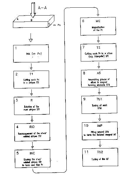
- Fig. 1 is a flow sheet of the method aceording to the invention.
- Figures from 2a to 29 repre6ent the main teps of the method according to
the invention.
- Figures from 3a to 3c represent some new magnet 6hapes that it is possible
to get with forming elements obtained preferably with the process according
to the invention.
- Figures 4a to 4c show totally yoked magnetic generators.
- Figures 5a and 5b show partially yoked magnotic generators.
In Fig.1 it is po~sible to see how at least one and in general m commercial
tile~ Pc of magnetic material (reprefiented in fig.2a) enter step 1 for the
marking MA.
The conventional tiles Pc are in fact defined by means nf length A, width B,
~oth perpendicular to the A-A axis, and by thickness S along such axis A-A,
which can be coincident with a po~sible anisotropy axis. Bach one of the m
tiles Pc idantified in this way undergoes, in step 2, a cuttin~ operation T1,
80 that from each tile Pc it i~ possible to get n ~trips STi havin~ the same
width B and thicknes~ S, whereas tho new length is A1, in ganeral given by the
formula:
A - k
A1 = ---------
n
where k i8 the poa~ible wasted material and n is a generic positive integer.
It is avident that A1 can be profitably cho~en according to circumstances and
that it con6titutes a high flexibi~ity parameter for the whole proce~ his
flexibility is directly uæable whenever it is wished to minimize the effects
of the ~inite length of the magnet, as described in the literature. In this
ca~e it i~ pro~itable to build the magnat using 6everal sections having a
def~ned length obtained by means of optimizing mathamatical calculation~.
These sections are then brought close one to the other in order to have gaps
of predefined width~ as ~ketched in fig.3~. The advantage of being able to
....
2~2~3~9
choose with a total freedom the thicknes~es of the element~ deriving from the
proce~sing is therefore significant.
As already explained, the set of input tile~ Pc can have cardinality m, so
that the set of strips STi at the output of step 2 can have cardinality
n * m, each strip being identifiad by means of the marXing MA carried out in
step 1 .
The n ~ m strips S~i coming out of the step 2 cutting operation are rotated,
in the step 3 rotation R, of such an angle that the A-A axis fall~ now in a
position different from that of the original Pc tile. In the most simple ca~e,
and therefore in the preferred one, there is a 9O rotation of the A-A axis
(8tep 3).
The rotation is followed by the step 4 re-arrangement (RIO), in which the
n * m strips S~i are grouped in 6et~ of n' strip~ each. The group~ ara formed
according to the individual marking and to a criterium that guarantees the
desired sim~atry and errors compen6ation ~haracteristics during the final
assembling.
In the same way, inside each group it is established an order of the n' strips
that ma~e up the group.
This re-arrangement process allows, together with the initial choices of
parameters n and m, to obtain the required simmetry characteristic~ of the
final assembly and/or the desired reduction of the errors deriving from the
imperfect nature of the initial tiles Pc.
~he rotated and re-arranged ~tripfi at the output of step 4 are then ~oined
with proper means, e.g. by glueing, during step 5. Tho strips ara grouped
ln sets of cardinality n' ln order to have p new tiles Pr according to the
invention; each new tile is made up of n' strips STr individually marked and
placed in a proper predefined ~equence, in order to obtain Pr tiles having
width B, thickness Sr = A1 ~both perpendicular to the rotated A-Ar axis) and R
new length n' * S , parallel to the axis A-Ar described above. Furthermore,
the Pr tiles obtained in this way have the desired characteristics of ~immetry
and compensation of the magnetic properties variations of the m commercial
tiles Pc at the input of the process. The number n' o~ strips that form a
group may vary from one group to any other group.
During steps 6 and 7 tthat can be indifferently carried out in the order
indicated in fig.l or in inverse order), the tiles Pr obtained with step S
undergo a magnetization process MG and a second cutting operation ~2; with
these two operations it is possible to get w magnetized slicas 9Pi, e.g.
triangular, trapezoidal, rectangular eta, as in fig. 2g.
During step 8 (AS), the slices SP1 are assembled in magnet forming elements
(~FM), formed by ~uxtaposing groups of slices SPi.
Each magnet forming element may optionally undergo, during step 9, a tuning
proce~s tTUl) in order to reduce the errors cumulated ~o far .
During step lO tIMP) several magnet forming elements tEFM) are piled in order
to form tha finished ~agnat t~F), that may optionally undergo, during ~tep 11,
the final tuning (TU2).
Figures 3a and 3b show, for examplification and according to an advantageou~ -
a~pect of the invention, how it has been pos~ible to get magnet Eorming
elements EFMi having different shapes and dimensions and able to adjust
themselves, according to circum~tance~, to different application requirements,
by juxtaposing slices SPi (from SP1 to SP12) having different ~hapes and
different orientations of the A-A axis.
Figures 3a and 3b show the most simple case of magnet elements having 4 sides
or fac~s; on each one of these are juxtaposed 3 slices ~e.g. SP1, SP6, SP5 in
the upper part of fig. 3a and SP1, SP2, SP7 in the upper part of fig. 3b). At
least some of the polygonal slice~ can profitably be chosen equal to one
another, e.g. SP1 = SP3 , SP2 = SP4 in fig.3a and SP1 = SP2 , SP12 = SP8 in
fig.3b .
Adjusting therefore dimensions, angles, orientations, magnetization, number of
segments of strips involved in the forming of each slice etc, it is po~sible
to achieve a high flexibility and modularity for the composition of forming
elements and therefore for the composition of magnets having the geometries,
structurea, field intensity etc needed to face ~11 kinds of requirements; it
~ill therefore be possible to reach every time a "maximu~ maximorum" of
characteristics, economies, efficiency and reliability.
Fig. 3c shows a magnet formed by elements from ~FM1 to EFM8, that may
themselves comply, at least partially, with modularity. Figures 4a to 4c, 5a
and Sb show magnets provided with yoke G, which is total in figures 4a to 4c
and only partail in figures 5a and 5b. In figure 4a the central cross-section
has an exagonally shaped cavity delimited hy magnetic material slices SP1 to
SP6. Fig. 4b showa the aame generator structure of fig. 4a provided also with
two polar expansions EPl and ~P2. Fig. ~c i9 a perapective view of said
~tructure and emphasizea ita composition as obtained by simply ~uxtaposing the
magnet forming ~lements EFM1 to EFM6. Figures 5a and 5b show respectively the
cross-section and the perspective view of a generator formed of slices SP1 to
SP14, and having yoke G only on the aide faces.
For clearness sake the invention has baen described with reference to the
preferred embodimenta repreaented in the drawings: it i9 nevertheless
understood that it is possible to bring into them variations, mo~ifications,
substitutions and alike, which, being in the reach of a person s~illed in the
art, fall within the scope and the spirit of the invention. In fact, the
sequence and the number of stepa in fig.1, the configurationa of the elements
represented in the figures from 2a to 2g, the geometries of figures 3a and 3b;
of 4a and 4b; and of 5a, can even be different from the onea deacribed and
shown ~e.g. "triangular" can be understood as "polygonal" and so on).
Needless to say that the process o~ the invention can also be used withi~otropic magnetic materials, commercial or not commercial, laminated or
otherwise formed.
The elimination of magnetic characteristics disuniformities can be carried out
by cutting the tile edge~ up- or down-~tream of step MA.