Language selection

Search

Patent 2020414 Summary

Third-party information liability

Some of the information on this Web page has been provided by external sources. The Government of Canada is not responsible for the accuracy, reliability or currency of the information supplied by external sources. Users wishing to rely upon this information should consult directly with the source of the information. Content provided by external sources is not subject to official languages, privacy and accessibility requirements.

Claims and Abstract availability

Any discrepancies in the text and image of the Claims and Abstract are due to differing posting times. Text of the Claims and Abstract are posted:

  • At the time the application is open to public inspection;
  • At the time of issue of the patent (grant).
(12) Patent: (11) CA 2020414
(54) English Title: METHOD OF CONNECTING PIPES OF PLASTICS MATERIAL OF A DOUBLE PIPE SYSTEM AND A PIPE CONNECTION MADE BY THE METHOD
(54) French Title: METHODE DE RACCORDEMENT DE TUYAUX EN MATIERES PLASTIQUES POUR RESEAU A DOUBLE TUYAU ET CONNEXION AINSI REALISEE
Status: Expired and beyond the Period of Reversal
Bibliographic Data
(51) International Patent Classification (IPC):
  • F16L 39/00 (2006.01)
  • B29C 65/20 (2006.01)
  • B29C 65/78 (2006.01)
  • F16L 47/02 (2006.01)
(72) Inventors :
  • WERMELINGER, JORG (Switzerland)
(73) Owners :
  • GEORG FISCHER AG
(71) Applicants :
  • GEORG FISCHER AG (Switzerland)
(74) Agent: ROBIC AGENCE PI S.E.C./ROBIC IP AGENCY LP
(74) Associate agent:
(45) Issued: 1996-03-19
(22) Filed Date: 1990-07-04
(41) Open to Public Inspection: 1991-01-08
Examination requested: 1993-11-18
Availability of licence: N/A
Dedicated to the Public: N/A
(25) Language of filing: English

Patent Cooperation Treaty (PCT): No

(30) Application Priority Data:
Application No. Country/Territory Date
02 538/89-2 (Switzerland) 1989-07-07

Abstracts

English Abstract


A method of connecting pipes of plastics material of a
double pipe system and a pipe connection made by the method.
The inner pipes of the pipe system are connected to each
other with a sleeve member by welding or gluing. Clamping
jaws are used for holding and moving the inner pipes toward
each other. The outer pipes are shorter than the inner pipes
at least by the thickness of the two clamping jaws. For
bridging the gap between the outer pipes, an expandable
intermediate ring is inserted in the gap. An electric
welding sleeve is used for connecting the outer pipes and the
intermediate ring.


Claims

Note: Claims are shown in the official language in which they were submitted.

I CLAIM
1. In a method of connecting pipes of plastics material
of a double pipe system having inner and outer pipes, wherein
the inner pipes are rigidly connected by means of a sleeve
member and the outer pipes are rigidly connected by means of
a welding sleeve, the improvement comprising holding the ends
of the inner pipes to be connected concentrically relative to
each other by means of clamping jaws and moving the ends of
the inner pipes axially together with the clamping jaws until
the inner pipes are rigidly connected by means of the sleeve
member, spacing the outer pipes apart at the connection
location by a distance which corresponds at least to the
thickness of the clamping jaws, pushing an expandable
intermediate ring which is provided with a radial slot over
the inner pipes after the inner pipes have been connected and
radially inserting the intermediate ring between the ends of
the outer pipes, and rigidly connecting the two ends of the
outer pipes and the intermediate ring to each other by means
of the welding sleeve.
2. The method according to claim 1, comprising gluing
the sleeve member to the inner pipes.
3. The method according to claim 1, comprising welding
the sleeve member to the inner pipes.

4. The method according to claim 1, wherein the welding
sleeves for connecting the outer pipes includes an electric
filament winding.
5. In a pipe connection of a double pipe system having
inner and outer pipes, wherein the inner pipes are rigidly
connected by means of a sleeve member and the outer pipes are
rigidly connected by means of a welding sleeve, the
improvement comprising clamping jaws for holding the ends of
the inner pipes to be connected concentrically relative to
each other and for moving the ends of the inner pipes axially
together until the inner pipes are rigidly connected, and an
expandable intermediate ring which is provided with a radial
slot, the intermediate ring being mounted radially between
the ends of the outer pipes, wherein the welding sleeve is an
electric welding sleeve and is mounted on the outer
circumference of the ends of the outer pipes and of the
intermediate ring.
6. The pipe connection according to claim 5, wherein
the intermediate ring has at both sides thereof a projection,
the projection resting against the inner circumference of the
outer pipes.
7. The connection according to claim 5, wherein the
intermediate ring includes a film-type hinge.

Description

Note: Descriptions are shown in the official language in which they were submitted.


`- - 2020414
BACKGROUND OF THE INVENTION
1. Field of the Invention
The present invention relates to a method of connecting
pipes of plastics material of a double pipe system, wherein
the inner pipes are rigidly connected by means of a sleeve
connection and the outer pipes are rigidly connected by means
of a welding sleeve.
The present invention also relates to a pipe connection
for a double pipe system manufactured in accordance with the
above-described method.
2. DescriPtion of the Related Art
In known double pipe systems, the outer and the inner
pipes are held concentrically relative to each other by means
of spacer members.
This makes it possible to manufacture a sleeve
connection of the inner pipes by concentrically clamping the
pipe systems at the outer diameter of the outer pipes.
In double pipe systems without relative centering of the
inner and the outer pipe, it is not possible to manufacture a
pipe connection using the above-described type of method.

` 2020414
`_
SUMMARY OF THE INVENTION
It is, therefore, the object of the present invention
to provide a method of the above-described type and a pipe
connection manufactured by means of the method, wherein the
inner and outer pipes can be connected rigidly without
concentrically holding the pipes by means of spacer members.
In accordance with the present invention, the ends of
the inner pipes to be connected are concentrically held
relative to each other by means of clamping jaws and the ends
of the inner pipes are axially moved together with the
clamping jaws until the inner pipes are rigidly connected.
The outer pipes are spaced apart at the point of connection
by a distance which corresponds at least to the thickness of
the clamping jaws. After the inner pipes have been
connected, an expandable intermediate ring which is provided
with a radial slot is pushed over the inner pipe and is
radially inserted between the ends of the outer pipes. The
two ends of the outer pipe and the intermediate ring are
rigidly connected by means of a welding sleeve.
In the connection of inner and outer pipes of plastics
material of a double pipe system manufactured by the above-
described method, the inner pipes are connected by means of a
sleeve connection. An expandable intermediate ring which is
provided with a radial slot is arranged between the ends of

` _ 2 û .~ 1 4
the outer pipes. An electric welding sleeve is arranged on
the outer circumference of the ends of the outer pipes and of
the intermediate rings.
The various features of novelty which characterize
the invention are pointed out with particularity in the
claims annexed to and forming a part of this disclosure. For
a better understanding of the invention, its operating
advantages and specific objects attained by its use,
reference should be had to the drawing and descriptive matter
in which there is illustrated and described a preferred
embodiment of the invention.
BRIEF DESCRIPTION OF THE DRAWING
In the drawing:
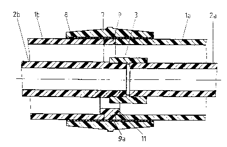
Fig. 1 is a sectional view of the ends of the outer and
inner pipes of a double pipe system prior to being connected;
Fig. 2 is a sectional view of the sleeve connections of
the inner and outer pipes of the double pipe system; and
Fig. 3 is a cross-sectional view of the intermediate
ring shown in Fig. Z.

202~
DESCRIPTION OF THE PREFERRED EMBODIMENT
Fig. 1 of the drawing shows the ends of outer pipes la,
lb and of inner pipes 2a, 2b prior to the manufacture of
sleeve connections. One of the inner pipe ends 2a is already
rigidly connected to a sleeve 3.
The connection of the inner pipes 2a, 2b is preferably
effected by means of a welding device. Clamping jaws 4a, 4b
are used for concentrically clamping the pipe 2a at the outer
diameter of the sleeve 3 and the pipe 2b at its outer
diameter outside of the length of insertion of the pipe 2b.
The clamping jaws 4a, 4b have in the clamping area and up to
the outer diameter of the outer pipes la, lb a thickness d
which is as small as possible, wherein the clamping jaws each
have a centering step 5 for simultaneously concentrically
fixing the outer pipes with play.
Subsequently, a heating device 6 with a heating
projection 6a and a heating sleeve 6b is swung into the
region between the ends of the inner pipes 2a, 2b. By
displacing the clamping jaws 4a, 4b in the known manner, the
inner diameter of the sleeve 3 and the outer diameter of the
pipe 2b are then heated by means of the heating device 6.
The heating device 6 is then swung out of the region of the
clamping jaws 4a, 4b and the welding sleeve connection is

- 2020414
obtained by moving the pipes 2a, 2b relative to each other by
means of the displaceable clamping jaws 4a, 4b.
As can be seen in Fig. 1, the outer pipes la, lb are
shorter by at least the thickness d of the clamping jaws 4a,
4b seen from the ends of the inner pipes 2a, 2b to be
connected.
The shorter length of the outer pipes la, lb is
necessary for concentrically holding the inner pipes when
they are connected. The gap created between the outer pipes
la, lb of at least 2d makes possible a visual examination of
the inner pipe connection with respect to tightness before
the outer pipes are connected. The outer pipes la, lb are
then connected by means of an electric welding sleeve 7 which
had previously been slid onto one of the outer pipes. Since
the filament winding 8 can also generate heat in the middle
portion of the welding sleeve 7, it is necessary to ensure
that the two ends of the pipes la, lb do not melt excessively
and collapse inwardly. This is prevented by inserting an
intermediate ring 9 into the gap between the ends of the
outer pipes la, lb.
As can be seen in Fig. 3, the intermediate ring 9 has a
radial slot lo. The intermediate ring 9 can be bent open to
such an extent that it can be placed over the sleeve
connection of the inner pipes 2a, 2b and can be placed

2~4~
between the pipes la, lb to fill out the gap therebetween, as
particularly illustrated in the upper portion of Fig. 2.
The welded connection is subsequently effected in the
known manner by means of the electric welding sleeve 7, so
that the ends of the outer pipes la, lb and the intermediate
ring are connected rigidly and fluid media-tight to the
electric welding sleeve 7.
In the configuration of the intermediate ring 9a shown
in the bottom part of Fig. 2, the intermediate ring 9a has a
greater wall thickness and a projection 11 at both sides.
This safely ensures that the pipes la, lb are prevented from
collapsing towards the inside.
As the lower portion of Fig. 3 shows, the intermediate
ring 9, 9a, if it has a greater wall thickness, can be
provided with a film-type hinge 12, so that the intermediate
ring can be more easily bent open.
Instead of the welded sleeve connection of the inner
pipes 2a, 2b, it is also possible to use a glued sleeve
connection, wherein it is also in this case necessary to
provide a concentric support by means of the clamping jaws
4a, 4b and the welding sleeve connection of the outer pipes
la, lb is constructed, as described above, by inserting the
intermediate ring 9, 9a.

2020~1~
While a specific embodiment of the invention has been
shown and described in detail to illustrate the application
of the inventive principles, it will be understood that the
invention may be embodied otherwise without departing from
such principles.

Representative Drawing
A single figure which represents the drawing illustrating the invention.
Administrative Status

2024-08-01:As part of the Next Generation Patents (NGP) transition, the Canadian Patents Database (CPD) now contains a more detailed Event History, which replicates the Event Log of our new back-office solution.

Please note that "Inactive:" events refers to events no longer in use in our new back-office solution.

For a clearer understanding of the status of the application/patent presented on this page, the site Disclaimer , as well as the definitions for Patent , Event History , Maintenance Fee  and Payment History  should be consulted.

Event History

Description Date
Inactive: IPC from MCD 2006-03-11
Time Limit for Reversal Expired 2001-07-04
Letter Sent 2000-07-04
Grant by Issuance 1996-03-19
Request for Examination Requirements Determined Compliant 1993-11-18
All Requirements for Examination Determined Compliant 1993-11-18
Application Published (Open to Public Inspection) 1991-01-08

Abandonment History

There is no abandonment history.

Fee History

Fee Type Anniversary Year Due Date Paid Date
MF (patent, 7th anniv.) - standard 1997-07-04 1997-06-23
MF (patent, 8th anniv.) - standard 1998-07-06 1998-06-19
MF (patent, 9th anniv.) - standard 1999-07-05 1999-06-17
Owners on Record

Note: Records showing the ownership history in alphabetical order.

Current Owners on Record
GEORG FISCHER AG
Past Owners on Record
JORG WERMELINGER
Past Owners that do not appear in the "Owners on Record" listing will appear in other documentation within the application.
Documents

To view selected files, please enter reCAPTCHA code :


To view images, click a link in the Document Description column. To download the documents, select one or more checkboxes in the first column and then click the "Download Selected in PDF format (Zip Archive)" or the "Download Selected as Single PDF" button.

List of published and non-published patent-specific documents on the CPD .

If you have any difficulty accessing content, you can call the Client Service Centre at 1-866-997-1936 or send them an e-mail at CIPO Client Service Centre.


Document
Description 
Date
(yyyy-mm-dd) 
Number of pages   Size of Image (KB) 
Abstract 1993-12-03 1 17
Claims 1993-12-03 2 64
Drawings 1993-12-03 1 53
Description 1993-12-03 7 198
Description 1996-03-18 7 198
Abstract 1996-03-18 1 19
Claims 1996-03-18 2 67
Drawings 1996-03-18 1 34
Representative drawing 1999-07-14 1 12
Maintenance Fee Notice 2000-07-31 1 178
Fees 1995-06-18 1 37
Fees 1996-06-13 1 23
Fees 1994-06-14 1 65
Fees 1993-06-29 1 35
Fees 1992-07-01 1 29
Prosecution correspondence 1993-11-17 1 43
Courtesy - Office Letter 1993-12-14 1 38
PCT Correspondence 1996-01-09 1 35