Note: Descriptions are shown in the official language in which they were submitted.
I~lT~OD AND APPARATUS FOR SIMULATING
OPEN FLAME BROILED MEAT PRODUCTS
Cross Reference To Related AEplications
This is a continuation-in-part of U.S. Serial No. 377,177
filed July 10, 1989 entitled Method and Apparatus for
5 Simulating Open Flame Broiled Meat Products
Field of the Invention
The present invention is intended for use in quick
service restaurants to automatically and uniformly cook meat
lO products in a manner which will simulate the appearance and
texture of meat products that ~re individually broiled over
an open flame.
Background of the Invention
Open flame broiled cook ng is highly desirable for
meat products sold for public consumption, and such products
. , have won wide customer acceptance based on their aesthetic
appearance and taste to the palate.
Open flame cooking however requires constant and
full time attention by a cook, and fxequently results in meat
products that are overdone in the thinner portions, and
underdone in thicker portions. While this can be regulated
to some extent by the thickness of the cut in beef products,
it is difficult, if not impossible to achieve when broiling
chicken or other irregularly shaped pieces of meat for sale
to consumers. In particular, it is difficult to achieve in
quick service restaurants which depend for the patronage on a
uniformly prepared product that will appear visually the same
and taste palatively the same each time the customer returns
to the restaurant. With manual open flame cooking, this is
dif~icult to achieve due to the differences in preferences by
individual cooks or chefs, and at times, the work load
imposed on a chef at peak lunch and dinner hours.
Therefore, there is currently a need in quick
service restaurants for a method and apparatus which will
:
rapidly and uni~ormly prepare meat products, particularly
l ~oultry products ~or consumption, wherein the product
~ppearance simulates the appearance of an open flame broiled
meat product.
5 Description of the Prior Art
U.S. Patent 3,707,145 to Anetsberger et al.
discloses a convection oven capa~le o~ temperatures to
produce pyrolysis therein. Structure includes a cooking
compartment, an outer shell and a space therebetween for
10 environmental air. Air is drawn by a fan to keep control
mechanisms and the exterior of the oven cool.
U.S. Patent 2,243,137, cited during the prasecution
of parent application U.S. Serial No. 377,177, discloses the
use of fins to conduct heat to a meat product during cook:ing.
U.S. Patent 4,297,942, cited during the prosecution
of parent application ~.S. Serial No. 377,177, discloses the
use of heated "branding rods" which mark the meat product
while conveying the product through a radiant cooking zone.
U.S. Patent 2,895,406, cited during the prosecution
of parent application U.S. Serial No. 377,177 discloses an
apparatus to clamp bacon strips together in a vertical
orientation, over a fat drainage trough to uni~ormly cook the
bacon from both sides without turnins same.
U.S. Patent 1,988,087 to Perone discloses an
enclosed broiler, heated from below, which is best
illustrated with respect to the present invention in Figures
4 and 5. A grill 15 is e~uipped with substantial upstanding
ribs 16 which supports 2 meat product to be cooked 18, which
is secured in place by means of a grill 20.
U.S. Patent 4,375,1~4 discloses an apparatus ~or
heating foods such as french fried potatoes which includes a
pan 9 a high speed air heating source generated by a fan
means 129, wherein the air passes through an open mesh grill
119 secured to the fan plenum.
.
U.S. Patents 685,342, 144,945, and 3,019,721 all
l ~isclose devices ~or facilitating the cooking of meat in a
broiler or oven which include a pan or pla~e for receiving
the meat, and a grill which overlies the meat at the time the
product is prepared. In addition, the '945 patent and the
5 '721 patent both disclose reservoirs for accumulating fat and
meat juices expressed from the meat product during cooking.
U.S. Patents 1,772,171 and 1,903,324 both disclose
devices which secure a product to be cooked between two
grills which are clamped together, wherein the food product
lO is heated from either side by radiant heat.
U.S. Patent 3,427,955 discloses a broiler pan
having a series of upstanding flat surfaces 18 for receiving
a meat product 24 to be cooked.
U.S. Patents 3,994,212 and 4,121,510 both disclose
15 broiler pans having meat product support corrugations which
extend transversely to the length of the pan.
Summary of the Invention
The present invention provides a method and
apparatus for rapidly and uniformly cooking meat produc~s
which simulates open flame broiling. The invention also
provides for pyrolytic self cleaning of ~he oven~ A light
weight aluminum pan means having a series of elevated crowned
portions for receiving and directly conducting heat from the
pan to the meat product is used in combination with a grill
means which is pre-coated with a browning agent to leave
carmelized grill marks on the meat product as it is cooked.
It is releasably secured to the pan and is effective to clamp
the meat product between the grill and the pan to a
predetermined thickness during cooking, to thereby aid in the
uniformity of the cooking process. The pan, meat product and
grill are placed in a high velocity air convection oven.
Alternating with the crowned portions in the aluminum pan are
indented reservoirs which serve to collect the fat and meat
juices which are expressed by the meat product during
.
: . ' `,. ' ~
.' ' '
.
~ooking. This preverlts the degradation of the texture,
1 Elavor and appearance of the meat product. During the time
the poultry is positioned in the convection oven, high
velocity convecting hot air sweeps over the irregular surface
of a poultry meat product to be cooked to break down the
5 boundary layer of air which normally surrounds the food
product. This results in rapid heat transfer to the food
product. The convecting air removes water from the surface
of the food product faster than moisture can migrate from the
center towards the surface thereby browning or searing the
10 surface of the food product without causing undesirable
drying of the interior portions of the product. The
combination of the pan and the convection oven results in an
improved product which is cooked in s~stantially less time
than conventional cook ovens and which results in a uni~orm
15 product appearance which simulates the appearance of a flame
broiled meat product. While the invention is equally
applicable to all meat products, it is particularly useful
for the simulation of open Elame broiled poultry or chicken
~ood products due to the irregular shape aI?d configuratioIl of
these food products.
It is therefore an object of the present invention
to provide a method and apparatus for uniformly and rapidly
cooking a meat product unattended by a cook while simulating
the appearance of an open flame broiled meat product. It is
another object of the present invention to improve the
consistency of both the visual appearance and the palatable
taste of the food product from batch to batch as compared to
manually tended open flame broiled poultry. It is another
object of the present invention to provide an apparatus which
may be unattended during use, except for loading and
unloading the oven with pre-assembled pans of meat products.
It is still another object oE the present invention to
significantly reduce the amount of labor involved in cooking
poultry pieces by providing pre-assembled pans oE chicken
parts which may be stored in a refrigerated housing until
.. . ; . . .
.
, . ~: .
.
immediately prior to cooking, thereby avoiding the time
1 consuming step of individually placing and turning individual
pieces of meat product on an open flame grill.
A Brief Description of the Drawin~s
Figure 1 is a top plan view of the pan of the
present invention.
Figure 2 is a side view of a pan of the present
invention illustrating a grill, pan and meat products clamped
therebetween.
Figure 3 is a top view of the grill of the present
invention.
Figure 3a is a side view of the grill illustrated
in Figure 3 illustrating a portion thereof in cross-section.
Figure 4 is a cross-section view of the pan
15 illustrated in Figure 1 taken at section line A,A'.
Figure 5 is a cross-section view of the pan
illustrated in Figure 1 taken at section line B,B'.
Figure 6 is a side view of a fixed clamp means used
to secure the grill to the pan.
Figure 7 is a side view of a releasable clamp means
utilized in the present invention which is used to releasably
secure the grill to the pan.
Figure 8 is an enlarged diagrammatic view of the
cross-section of the crowns and reservoirs formed in the pan
illustrated in Fiyures 1, 4 and 5.
Figure 9 is a exploded diagram of the inner
assembly of the convection oven of the present invention.
Figure 10 is a front elevation of two stacked
convention oven of the present invention illustrating the
control module on the side thereof.
Figure 11 is an interior view of the cooking
compartment illustrating the fan means, heating elements and
conventional rack support me~bers.
.
~ ,
.
. . . ';
~ -6- ~
Figure 12 is a diagrammatic view illustrating the
l sooling air passageway used in the convection oven of the
present invention.
Detailed Description of the Preferred Embodiments
The present invention is for a method and apparatus
5 for cooking meat products in a quick service restaurant,
particularly irregularly shaped poultry meat products. The
invention includes the use of conductlon radiation and
convection heating with rapidly moving heated air to cook
irregularly shaped meat products, while simultaneously,
10 safely removing expressed fat to preserve the texture and
appearance of the meat product. Such air removes the cool
air barrier around a meat product to effect more consistent
and better cooking. Concurrently the invention utilizes a
modified pan, which was disclosed in the parent application
in its original form, to impact an open flame broiled
appearance to the meat product.
In the parent application, U.S. Serial No. 377,177,
the entire disclosure of which is incorporated herein by
; reference thereto, the benefits of an air impingement oven in
conjunction with a pan for producing a desirable meat product
was disclosed. However, in extended use, the oven was
difficult to clean. Vaporous fat quickly coats the inside of
the oven, requiring high temperature steam or caustic
cleaning, both of which are impractical in a quick service
restaurant. As described in the present invention, an oven
design which cleans itself by means of pyrolysis is
pre~erred. Such an oven is substantially disclosed in U.S.
Patent 3,707,145 to Anetsberger, et al., the entire
disclosure of which is incorporated herein by reference
thereto.
In order for an oven to reach temperatures where
pyrolysis takes place, it is necessary to seal off the
cooking compartment. The oven of the parent application
could not be sealed, and it was therefore not possible to use
pyrolysis for cleaning. When the doors of the oven used in
'
.
. '
~h~ present invention are closed, the oven is sealed and
1 ~emperatures of pyrolysis may be produced. Another concern
relative to production of such high temperatures is the
external temperature of the oven relative to both the safety
of personnel and the protection of control mechanisms for the
5 oven. Therefore a space has been provided for the flow of
cooler air from the environment between the cooking
compartment and the outer cover for the oven. The passage of
air in this compartment provides a "cool to the touch"
feature for the outer cover of the oven and protects the
10 control mechanisms from elevated temperatures.
The pan of the parent application has also been
modified, to be used more effectively in conjunction with the
present convection oven. The side walls of the pan have been
altered, and the crown configuration has been altered to work
15 more efficiently with a convection oven. Figures 1-8
illustrate the modified pan of the present invention.
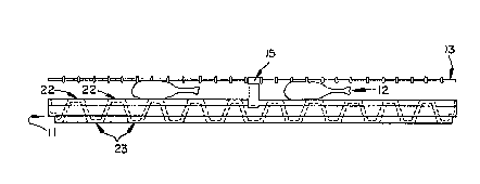
As illustrated in Figures 1 8, the pan comprises a
pan 11 which supports a meat product, such as a chicken drum
stick, to he cooked. As will be hereinaf~e~r illustrated with
respect to Figures 4 and 5, the pan has two series of
elevated crowns 22, separated by a trough 29, for receiving
and directly conducting heat from the pan to the meat product
to be cooked. The crowned portions alternate with a
plurality of reservoirs 23, which feed into trough 29, for
collecting fat and juices expressed by ~he meat product
during the cooking operation. A grill 13 overlies the meat
product 12 and is releasably mounted to pan 11 by means of
clamps 14, 15 which will be hereinafter further explained
with respect to Figures 3, 6 and 7. The grill is removed
from the pan during placement of the meat product, and when
the pan is loaded for cooking, the grill is mounted to clamp
the meat to a predetermined thickness between the crowns of
the pan and the underside of the grill.
When the pan is in the convection oven the heated
air sweeps both the surface of the meat product 12 to be
.
'
~ -8- ~
cooked and the underside of the flats o~ the pan 11 to
l convect heat thereto, and thereby cook the meat produ~t. In
order to simulate the appearance of an open flame broiled
product, it is necessary to brown or sear the surface of the
meat product 12. Browning or searing cannot be accomplished
5 on the surface of a moist food product as long as moisture
migration and eva~oration keep the surface damp and cooler
than the searing temperature of the product. Rapid browning
requires heating the product with the convecting hot air at
approximately 350F while searing or grilling requires
lO heating of the product surface to about 400F or higher. The
convecting hot air moves about the inner compartment at
velocities of 800-1100 feet per minute at a temperature of
~ 400-495F to sweep over the surface of the food product as
:~ the hot air is circulated through the oven. The preferred
15 cooking temperature is 475-495F. The convecting air
removes the boundary layer of air which surrounds a cool food
~ ~ product and results in a rapid heat transfer to the product.
: The water is removed from the surface of the product faster
than moisture can migrate from the center,qf the product
towards the surface. This results in browning or searing
without causing undesirable drying of the interior portions
of the product. In a normal oven, the temperature of the air
heatlng the product can easily be more than twice the
temperature of the boundary layer immediately adjacent to the
product. Since the cool air is substantially denser than
heated air, there is a significant lag in the transfer of
heat to the product to be cooked. Radiant heat, while
; penetrating the boundary layer, requires relatively high
temperature at the source of the radiation, which results in
a substantially higher heat gradient between the surface of
the food and the interior of the food. Thus as the surface
browns from radiant heat, the brown and dried surface acts to..
inhibit further heat transfer to the interior of the food
product. This forms an insulating layer which prevents the
migration of moisture from within, while continuing to absarb
: .
. .
;:
:: ,
9--
heat and brown on the surEace. For food products of
1 relatively uniform cross-section, this temperature gradient
can be adjusted to provide the desired cooking result in the
meat product. However, for irregular food products such as
drumsticks or chicken breast with wings, the smaller thinner
5 portions of the meat product become overcooked by radiant
cooking before the interior of the thicker portions of the
product are properly cooked.
A convection oven however uses a source air
temperature which is substantially lower than the source
10 temperature of a radiant heat source. This results in a
milder and more controlled browning or crisping of the
surface, and a more controlled heat transfer to the interior
of the product.
The present invention uses air convection heating,
and conductive heating from the pan to cook the meat product.
In addition, there is some radiation from the walls of the
cooking oven and the pan which assists in cooking the meat
product. The surface of the meat product is cooked by the
convecting hot air, while the pan transmits additional heat
directly to the food product through heat conduction.
~ s illustrated in Figure 2, the meat product 12 is
clamped betwe~n grill 13 and the crowns 22 of pan 11. The
pan 11 is illustrated in side view with ~he interior of the
pan shown by broken lines. Alternating between the crowns 22
of the pan are resèrvoirs 23 which collect Eat and meat
juices expressed or rendered from the meat product during the
cooking operation. Because o~ the relatively high Fat
content of a meat product, it is not feasible to cook the
meat product directly in a convection oven since the fat will
collect on the bottom surEace of the inner compartment and
create both a health and a fire hazard.
Several alternate pan designs have been tested,
some of which did not cook the meat uniEormly and some of
which had additional problems with rigidity, strength, the
.,
,- ' :
~ o- ~
rate o~ heat transfer, or allowing the fat to come into
l contdct with the food product during the cookiny operation.
The final design of the pan provides significant
contact portions 22 which permit direct conductive heat
transfer into the food product to be cooked, with spaced
5 alternating truncated V-shaped reservoirs 23 which collect
the fat and juices expressed during the cooking thereof. In
addition, the grill 13 is used to clamp the food product 12
to the flat crowned contact areas and thereby provide
conductive heat transfer and a relatively uniform
lO cross-section for more consistent internal cooking of the
meat product. The clamping action of the grill deforms the
meat product to be cooked, and urges it into contact along
the upper portion of the crowns to maximize conductive heat
transfer. The contour of the crowns enables the juices and
fats to be more easily collected in the reservoirs 23. In
one test between the pan design illustrated in Figures 4 and
5, and a conventional herringbone pan, a chicken meat product
was cooked in each pan under the same conditions and the
final product compared. The pan illustra~ed in Figures 4 and
5 produced an aesthetically pleasing product with piece
internal temperatures of 190 to 210F, and with the proper
color and doneness. The herringbone pan design however,
produced a product with internal temperatures of 165F to
190F, which was not completely cooked, and was pale on the
underside.
In addition to providing a uniform meat thickness,
the grill means 13 also creates a method of generating
simulated burn marks on the sur~ace of the meat product which
emulates those created by open flame grilling. The top rack
is roughened on the underside as indicated at 25b in Figure
3a and then coated with a browning agent which carmelizes
during the cooking cycle leaving lines on the surface of the
food product wherever the top rack has touched it. The
carmelizing agent is dextrose which may be suspended in water
or in cocoa butter for stick application. As illustrated in
" , ~
:
~igure 3, the grill 13 is constructed of a round 1/4 inch
l stainless steel perimeter rod 24 having a round cross-section
as illustrated at 24a, and upon which is secured a series of
quarter inch round cross-section stainless steel rods 25 as
illustrated in cross-section at 25a. The round rods are
5 secured by wrapping as illustrated in Figure 3a, and may be
further secured by welding lf desired to eliminate grease
entrapment cavities. The grill is clamped to the pan by
means o~ clamp means 14, 14a and 15 which cooperate with a
perimeter rib 26 Eormed on the exterior of pan 11.
In the preferred embodiment of the present
invention, pan 11 is formed from a single sheet of hardcoat
anodized aluminum in a stamping operation which creates a
series of angular corrugated reservoirs 23 having a width H
at their flat bottom portions of approximately one-quarter
inch as illustrated in Figure 8 and a depth d of
approximately one inch. The stamping process creates a
series of crowns 22 as the metal is drawn to the upper most
portion of the crowns 22. The side ribs 26 may be formed as
illustrated in Figures 5-7,. The sides of the pan extend
only to the level of the ribs and no higher such that
convecting air is not inhibited in reaching the meat product.
These ribs, together with the transverse orientation and
spacing of the reservoirs 23 provide enhanced stability and
rigidity for the pan as compared to conventional herring~one
or corrugated design. In the preferred embodiment, the
aluminum is then coated with a "non-stick" fluoropolymer
coating, such as sprayed Dupont SupraR to aid in the
cleansing of the pan after each use.
The grill is clamped to the pan by clamps that are
illustrated in-Figures 3, 6 and 7, wherein Figure 6
illustrates the fixed clamps 14, 14a which secure the grill
to one side of the pan, and Figure 7 illustrates a moveable
clamp 15 which is clamped to the opposing side wall rib 26a
after the meat pxoduct has been loaded. By adjusting the
effective clamp length d2 as illustrated in Figures 6 and 7,
.
- ~ -12- ~
~h~ grill may be adapted to any desired thickness of meat
l product, and will secure and flatten the meat product against
the crowns 22 of the cooking pan 11 when clamped thereto. In
construction, the clamp illustrated in Figure 6 is formed of
a single bend of sheet stainless steel which is welded to the
5 eY.terior perimeter rod 24 as indicated at 14a. The filling
of the cavity with weld material also minimizes the amount o~
grease that can be trapped within the crevices. The single
bend 14b extends inwardly and is secured against the lower
most portion 26a of reinforcing rib 26. The dimension d2 is
lO varied, depending upon the thickness of the meat product to
be cooked. If thicker pieces of meat are to be cooked, then
d2 will be greater. The grill does not contact the
reinforcing ribs 26, or pan 11, except through clamps 14 and
15.
The releasable clamp 15 is formed of a single sheet
which is multiply folded as illustrated in Figure 7 to
provide a hinged engagement with perimeter rod Z4 by virtue
of the curve formed in the clamp as illustrated at 15a. The
doubled over portion 15b provides a clamp.for securing the
grill to the perimeter rib 26, while the upstanding single
thickness 15c provides a thumb release for engaging and
disengaging the clamp from the perimeter of rib 26.
In the preferred embodiment of the invention the
pan and grill are 17 inches long and 16 1/2 inches wide with
a pan depth of approximately one inch. As illustrated in
Figures 4 and 5, the walls of the pan also stand one inch
tall and are offset by 1/4 inch as indicated at 6 and 6' from
the bottom to the top of the wall. The two series o~
reservoirs 23 are divided by a trough 29 which is one inch
wide as indicated at E in Figure 5. Each of the reservoirs
23 and each of the crowns 22 has a flattened portion
~pprox.ima~ely ~" in wid~h, as illustrated at ~I Figure 8.
There is center line d~stance between the reservoirs of
aE~pr4ximately 1 5/8 inches, as indicated at W in Figure 8.
:. ' '' :
:: :
. , . :. .
: '
13
~s illustrate~ in Figure ~, the convention oven of
l t~le present invention includes an inner cooking zone
consisting of an inner housing assembly 5Q which forms 4
sides of a cube, open on the front and bottom. A baffle 50a
is attached by a plurality of latches to the innex housing 50
5 to form the bottom of the cube. A bottom pan 50b is arranged
therebelow. Intermediate side walls 51, intermediate top wall
;4, and base members 53, 50 are fixedly attached to the
housing by welding. The remaining opening in the cube is the
frontal access to the inner cooking zone.
Side insulation 56, rear insulation 57 and top
insulation 58 are arranged around the intermediate walls of
the inner cooking zone. The insulation serves both to retain
heat inside the oven while also preventing the outside of the
oven from becoming dangerously hot during pyrolysis. Right
side and left side insulation covers 59 and 60, and rear
insulation covers 60 and 62 retain the insulation in it's
desired location. The upper edges of the insulation layers
56 are protected by top edge insulation covers, as
illustrated at 66.
Figure 9 also illustrates a front insulation panel
63 and doors 64 and 65. The doors 64, 65 are mounted on pins
64a and 65a at their top ends and bottom ends, and attach to
the oven to act as hinges so that the doors may be swung
open. The doors may be either connected by cams such that
upon opening one door the other will automatically open or
they may be singly opened.
There is a ~urther outer covering on the convection
oven as illustrated in Figure 10-12 which is spaced
equidistantly from the insulation covers 59-62 to create an
interconnecting cooling passageway in which ambient air is
propelled by a cooling fan means. The cooling passageway
thus reduces the temperature o~ the outside of the oven
during both the cooking operation and durlng the pyrolytic
self cleaning cycle.
`~ '` , ' ' ''
Figure 11 illustrates both the electric and gas
1 embodiments of the oven of this invention. It is to be
understood~ however, that only one method of heating at a
time is used in a given oven.
As illustrated in Figure 11, arranged within the
5 interior of the inner cooking zone are several rack supports
70 mounted in a conventional manner. These rack supports
hold a number of pans of this invention during the cooking
cycle. At the rear of the cooking zone are a fan means and
heating means 72 (for an electric oven embodiment only) for
lO creating high heate~ velocity convecting air. The cooking
zone fan 73 is capable of withstanding temperatures of up to
538C (1000F) which provides a safety margin for use during
the pyrolytic cleaning cycle to be discussed later. The an
itself is 24cm in diameter, with 48 blades, each of which is
5cm wide, with a forward curve design. The fan rotates
clockwise at a speed of 1725 rpm with a 60 hertz power supply
(at 50 hertz power the rotation speed is diminished to 1450
rpm). The fan is rotated by a 560 w or 3/4 horsepower motor
83 illustrated from the rear in Figure 12. Baffle 68,
illustrated in Figure 9, aids the fan in creating a uniform
flow of air. The baffle 68 measures approximately 54cm x
60cm, has a hole 76 in its center, and is mounted at the rear
of the housing immediately in ~ront of the fan. The bafle
directs incoming air through the central aperture 76 to the
fan from the cooking zone and directs the air flow from the
fan outwardly and around the periphery of the baffle thus
creating a uniform air flow pattern throughout the cooking
area. The air flows in a cyclical pattern from the center of
the oven into the fa~ means, past the heating means 72, out
around the baffle along the periphery of the inner walls and
back to the center of the oven. The airflow within the oven~
over the racks of chicken, flows at 800 to 1100 fpm.
Further illustrated in Figure 11 is an electric
heating element 72 which provides the heat for both cooking
o the meat product and for pyrolytic selE cleaning. It is
. ~ :
.~ . . .. , `
~o nc undcrstood, however, that gas or LPG ~Liquid ~ropane
l Gas? burners can be substituted for the electric e~ement.
Where electric heating element~ are used, there are
preferably 6 calrod heating elements, each rated at 1.83 kw.
The heating elements are disposed in rectangular
5 configuration around the cooking zone fan, between the baffle
and inner rear wall. The heating means is designed to
maintain a near constant 232-257C (450-495F) temperature
for cooking, but yet be capable of reaching 455-482C
~850-900F) for the pyrolytic self cleaning cycle.
lO Temperature within the cooking zone is monitored and
maintained by a computer attached module 80 illustrated in
Figure 10.
Where gas is used as the source heat it is
preferred to regulate the flow thereof to 8.64cm (3.4 inch)
water column pressure. The preferred nozzle is a No. 25
orifice mounted on two cast iron atmospheric burners 74
(illustrated in Figure 11) which in combinatlon with the
regulated gas flow delivers 33.7 kw ~125,000 BTU/hr) of heat.
The burners are disposed below the bottom.bafle 50a (shown
in Figure 9) of the inner cooking zone and the heat produced
thereby is directed along the bott~m of the housing by baffle
75 (illustrated in Figure 11) and is channeled through at
least one flue which is formed in close proximity with at
least one of the inner walls of the inner cooking zone. The
heat flowing therethrough is absorbed into the inner walls of
the inner cooking zone and transmitted therethrough. The
transmitted heat is then convected through the interior of
the inner cooking zone by fan means 71.
During the pyrolytic ~chemical decomposition from
heat) self cleaning cycle the internal temperature of the
oven reaches 455-482C ~850-900F) and must remain at that
temperature for 15-20 minutes. This puts a great deal of
thermal stress on components such as the convection fa~,
motor and control mechanism. The construction described
herein takes into account the high temperatures of pyrolysis
.
,; '
16- ~
~nd the detrimental effect it may have on the control, fan
l and motor necessary for the operation of the oven.
As illustrated in Figure 12, there is an
i~terconnected space 80 between the inner cooking zone within
the inncr housing 5~ and the outer cover 81. Disposed in
5 this space at the rear of the oven is a second fan 82 which
is connected to the same motor 83 and drive shaft as the
convection fan 71 within the cooking zone. The second fan
operates to draw cooler air from the surrounding environment,
as indicated by arrow A, through the fan 82 and into duct 87.
lO Duct 87 connects with a lower plenum 86 which extends under
the oven and connects with passageway 80 through a plurality
of openings, two of which are illustrated at 84 and 85. The
cooling air then circulates upwardly along the walls of the
inner cha~ber and is then expelled to the surrounding
15 environment at the top thereof as illustrated by the arrows
B,B'. This transient air is utilized to protect the.control
mechanism and fan motor for the oven, and also functions to
maintain a lower exterior temperature for the oven which
prevents injury to personnel who may cont~ct the outer wall
81 during the pyrolysis cycle. This air does not however
effect internal temperatures due to the insulation next to
the inner walls of the oven. As another safety feature,
there is provided a safety lock, which will not allow the
doors to be opened when the internal temperature is above
260-288C. This type of safety mechanism is known in the
art.
As illustrated in Figure 10, in the preferred
method of the present invention, the pans are placed in the
convection oven in the center of each shelf. This provides
for better air flow and therefore better cooking of the
product.
The combination of the pan configuration, the
grill, pan placement and the convection oven creates a
superior cooking apparatus which is able to significantly
reduce the cook time re~uired to cook a meat product, while
,; '
. , :
:',
:' . ~: '
-17-
~imultaneously simulating the visual appearance and texture
l of an open flame broiled food product. The convection oven
also enjoys the additional benefit of self cleaning by
pyrolysis. Since the temperature and airflow of the
convection oven are controlled by control means 80
5 illustrated in Fiyure 10, the cooking is completely
unattended, except for the loading and unloading of pans of
food products from the support racks.
3o
,: ~
.