Note: Descriptions are shown in the official language in which they were submitted.
2 0 2 û 8 9 2 TOL 2-0 1 1
LOAD CELL MOUNTING FOR ROTATIONAL CONTROL
Back~round of the Invention
Over the recent past, weighing systems have been developed
employing load cells structured in the manner of the so-called "rocker pin".
An important advantage realized with this innovation stems from the self-
erecting characteristic of the rocker pin configuration. When the normally
5 upright pin is deflected by a horizontally directed force component
experienced within the weighing system, it will return to its upright position
when the deflecting force terms are removed. A detailed description of
such load cells is provided in Dillon, et al., U.S. Pat. No. 4,815,547, issued
March 28, 1989, entitled "Load Cell" and assigned in common herewith.
Generally, a number of the rocker pin configured load cells are
supported in freely pivotal abutting fashion at their lower end by a ground
base through the medium of a receiver component or the like From this
lower contact, the cells extend in vertical columnar fashion to an upper
contact surface which, again, is in freely abutting contact with the
downwardly disposed surface of a platform ol frame having a loading
surface adopted to carry the load to be weighed.
The self-erecting feature is developed by configuring the cell or pin
component thereof so that the radius of curvature of each end or contact
surface is greater than on~half of the total height of the pin. Supported
upon such load cell structures, the scale platform and associated horizontal
loading surface exhibit several degrees of freedom of rnovement. Thus it is
necessary to accommodate for temporary transverse forces or side loads or
lateral forces induced by eccentric loading. For example, when weighing
vehicles such as trucks, forward movement and braking, as well as
maneuvering during scale entry will be the occasion of acceleration,
deceleration, and induced turning rnoments and the lilce imposed through the
platform in addition to vertical weight force vectors. Typically the extent
of lateral travel of the platform is restricted to within sm~ll tolerances by
bumper structures.
Instrumentation of the rocker pin configured load cells is provided
through the media of strain gauges coupled with the columnar or roclcer pin
components of the structure. This instrumentation mfly, for example, be
-1- ~
2020892
protected by employing conventional circuit potting procedures or, may be
contained within a protective, sealed, can-like enclosure suspended about
the central portion of the rocker pin configured counterforce. Necessary
power source inputs to and signal outputs from the enclosed circuitry
5 typically extends through a port or connector connected at the side of the
enclosure. Requisite cabling or wiring extends from that connector to
power and data gathering systems and the lilce.
~ ield experience with these weighing systems has revealed that the
temporary transverse or side forces associated by the n'oted dynamic loads
10 will engender a turning movement in the load cells about the longitudinal or
column~r axes of the rocker pin structures. This rotational movement is
developed by the somewhat rolling interaction of the contact surfaces of the
load cells with an associated support or platform surface. While rocker pin
structuring provides for a return to vertical upon removal of transverse
15 loads, the point of contact of such surfaces may vary to evoke a point-to-
point progression, the motion of the cells being observed to be somewhat
precessional in nature. Particularly where the temporary lateral forces at
the weighing platform are bi-directional or, in effect, rotational, this
progression of contact point positions, induces turning force vectors within
20 the load cells to promote this rotation. Such rotation can be destructive to
any appurtenances extending from the load cells. In this regard, the
rotation tends to stress or "wind up" cabling or wiring extending to the load
cell instrumentation, causing its brealcage with resultant operational loss
N ecessary repair to the load cells typically involves a substantial labor
25 investment associated, for example, with the jacking up of the platform, the
correction of an affected cell and a recalibration of the weighing system.
To avoid these encumbrances, a technique is called for which restricts such
rotation within acceptable tolerances but which does not affect the dynamic
performance of the load cells themselves.
Summary
The present invention is addressed to an improved load cell mounting
within weighing systems developing not only load induced vertical vectors of
force but also dynamic, transversely induced force vectors. The load cells
35 provided with these weighing systems are structured to incorporate
instrumented rocl<er pins which are normally vertically oriented and serve as
the counterforce component of the cells, thus a correction is required for
2020892
avoiding load cell rotation. A technique has been achieved with the
invention for limiting such rotation to acceptable tolerances through a
recognition of the transient nature of such rotation inducing force vectors.
In one control approach, rotation of these rocl~er pin containing load cells is
abuttably restricted while a requisite freely-abutting and freely pivoting
mounting of the cells is maintained. In unother control technique, a
resilient member is coupled with a load cell prone to such rotation in a
manner wherein it is resiliently loaded only by the transient rotational
vector forces. As these rotational forces subside, the rotationally induced
but stored energy of the resilient member returns the load cell to its initial
orientation, even though the load cell remains under a load induced
compressive state. This return rotational motion is achieved inasmuch as,
upon removal of the vector induced rotational forces, it has been discovered
that the cells are readily rotated by relatively small spring developed
l S f orces.
Another feature of the invention provides a weighing apparatus which
includes a base, a load receiving surface, at least one self-erecting rocker
pin load cell positioned between the base and the load receiving surface for
supporting the load receiving surface. The load cell has a longitudinal axis
and the apparatus includes means for restricting rotation of the load cell
about the longitudinal axis.
As another feature, the invention provides a method of constructing a
self-stabilizing vehicle scale on a base which comprises the steps of
positioning at least one self-erecting rocker pin load cell in an upright
position on the base, the load cell having a longitudinal axis and the lower
surface in contact with the base, and an upper contact surface;
supporting a load platform on the upper contact surface of th~
load cell; and
restricting rotation of the load cell about the longitudinal axis.
As another aspect, the invention looks to a weighing system wherein a
load to be weighed exhibiting both vertical and temporary transverse force
vectors is positioned upon a load platform load receiving surface having
freedom of movement, the load platform being supported upon load cells
each with a given external surface and formed having a self-erecting rocker
pin configured as a counterforce, each rocker pin having an axis along its
lengthwise extent und oppositely disposed upper and lower contact surfaces
of predetermined radii, the lower contact surface being mounted in freely-
202G892
pivotal abutting contact at the~ upwardly disposed surface of a lower
receiver supported from a ground base support and the upper contact
surface being mounted for freely pivotal abutting contact with the
downwardly disposed surface of an upper receiver supported by a load
5 platform support to compressively receive the vertical force vectors, the
point of the freely-abutting contact being variable with respect to
movement of the platform occasioned by the transverse vector forces and
creating transient rotational vector forces urging the rocker pins to rotate
about the axis. The invention provides an improved rocker pin counterforce
10 configured load cell mounting which includes a restrainer arrangement for
providing a stable reference isolated from the rocker pin. Additionally, a
rotation limit urrangement is coupled with the restrainer arrangement which
is contactable with the load cell for restricting rotation thereof within
predetermined limits by counteracting only the rotational force vectors
15 while not affecting the vertical force vector induced compression reception
and not affecting the freely pivotal mounting of the rocker pin.
As another feature, the invention provides a load cell rotation
restriction method for use in a weighing system wherein a load to be
weighed exhibiting both vertical and temporary transverse force vectors is
20 positioned upon a load platform lo~d receiving surface having freedom of
movement, the load platform being supported upon load cells each formed
having a self-erecting rocker pin configured as a counter-force, each rocker
pin having an axis along its lengthwise extent and oppositely disposed upper
and lower contact surfaces of predetermined radii, the lower contact
25 surface being mounted in freely pivotal abutting contact at the upwardly
disposed surface of a lower receiver supported from ground base and the
upper contact surface being mounted for freely-pivotal abutting contact
with the downwardly disposed surface of an upper receiver supported by the
load platform to compressively receive the vertical force vectors, the points
30 of the freely abutting contacts being variable with respect to movement of
the platform occasioned by the transverse force vectors and creating
transient rotation~l vector forces urging the rocker pins to rotate about the
axis. The method comprises the steps of:
providing a restraint component for the rocker pin configured
35 load cells to limit the extent of rotation to within two predetermined
abutting positions;
202089~
positioning the restraint component for force transfer freely
abutting engagement with the roclcer pin to retain the rotation within the
two abutting positions while not affecting the vertical force vector induced
compressive reception or the freely pivot~l movement upon the lower
5 contact surface; and
carrying out an evaluation of the ver tical force vectors
subsequent to the termination of the transient rotational vector forces.
As another feature of the invention, a method is provided for
restricting rotation of the rocker pins employed within load cells of the
10 above-described weighing system which comprises the steps of:
providing a resilient member deformable frorn an initial
orientation to a second orientation to store energy and which is releasable
from the second orientation to return to the initial orientation; and
coupling the resilient member with the rocker pin in a manner
15 wherein the member is deformable to the second orientation only by the
transient rotational vector forces effecting rotation of the rocker pin from
a first position, and the resiiient member is subsequently released from the
second orientation upon removal of the transient rotational vector forces to
return substantially to the initial orientation while drivably returning the
20 rocker pin substantially to the first position.
As another aspect of the invention, a load cell assemblage is provided
for use in a weighing system wherein a load to be weighed exhibiting
vertical and temporary transverse force vectors is positioned upon a load
platform load receiving surface having freedom of movement and which is
25 supported by the assemblage above a ground base. The assemblage includes
a rocker pin configured as an instrumented counterforce component having
an axis along its lengthwise extent and upper and lower contact surfaces of
rocker pin defining radii, the upper contact surface being in freely abutting
compressive force transfer contact with the load platform and the lower
30 contact surface extending to a peripherally disposed upstanding positioning
surface, the positioning surface having a non-circular portion extending
normally to the axis and of predetermined configuration and extent. A
receiver is positioned to receive the vertical force vectors and has a
receiving cavity with a support surface for supporting contact with a rocker
35 pin contact surface, the cavity having upstanding side surfaces configured
for effecting freely pivotal rnovement of the rocker pin about its contact
with the support surface and including n non-circular portion of
2020892
configuration corresponding with and of lesser extent than the
predetermined configuration of the positioning surface, so as to permit
freely abutting contact between the rocker pin positioning surface and the
receiving cavity side surfaces non-circular portion, restricting rotation of
the rocker pin about the axis during the freely pivotal movement.
Other features of the invention will, in part, be obvious and will, in
part, appear hereinafter. The invention, accordingly, comprises the
apparatus, system, and method possessing the construction, combination of
elements, arrangement of parts and steps which are exemplified in the
following detailed description.
For a fuller understanding of the nature and objects of the invention,
reference should be had to the following detailed description taken ir.
connection with the accompanying drawings.
lS Brief Description of the Drawin~s
Fig. 1 is a perspective view of a weighing facility incorporating the
features of the invention with portions broken away to reveal internal
structure;
Fig. 2 is a partial sectional view taken through the plane 2-2 of Fig. l;
Fig. 3 is a top partial view of a portion of the facility of Fig. 1 at the
location represented by Fig. 2;
F ig. 4 is a sectional view taken through the plane 4-4 in Fig. 2;
Fig. 5 is a sectional view of a receiver utilized in conjunction with Fig.
4;
Fig. 6 is a partial front view of a rocker pin component employed with
the load cell configuration of Fig. 4;
Fig. 7 is a partial sectional view taken through the plane 7-7 in Fig. 4;
Fig. 8 is a sectional view of an alternate embodiment for the invention
represented in Fig. 4;
Fig. 9 is a partial side view of another configuration of the instant
~nventlon;
Fig. 10 is a partial front view of the load cell configuration shown in
~ig. 9;
Fig. 11 is a partial top view of the load cell mounting configuration
shown in F igs. 9 and 10;
Fig. 12 is a top schematic view of another embodiment of a load cell
mounting configuration according to the invention;
2020892
Fig 13 is a schematic partial top view of another load cell mounting
configuration according to the invention; and
Fig. 14 is a schematic and partial sectional view of still another
configuration of the load cell mounting assemblage according to the
5 invention.
Detailed Description of the Invention
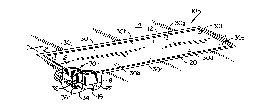
Referring to Fig. 1, a platform weighing facility structured in
accordance with the invention is revealed generally at 10. The facility 10 is
10 configured, for example, for the purpose of weighillg elongate loads such as
trucks or the like. Consequently, the facility 10 is seen to be positioned
such that the load receiYing surface 12 is located to facilitate the entrance
of trucks upon and exit therefrom. While the instant representation shows
receiving surface 12 to be at ground surface, other structures may be
15 employed. For example, surface 12 may be elevated above ground surface
14 and accessed by entrance and exit ramps. For any such design, the
positioning of a truck or the like upon the surface 12 will result in the
generation of both vertically imposed load vectors as well as temporary or
very short term dynamic transverse loads which will be manifested as
20 horizontal or transverse force vectors. Upon occasion, these transverse
vectors of force will be of such diverse horizontal directions as to impose-
essentially a circular movement into the surface 12. Surface 12 is seen
supported by and represents a component of a load platform represented
generally at 16 which typically is provided as a rigid structure formed of
25 steel members, one of which is shown at 18. Load platform 16 and its
associated load receiving surface 12 additionally are seen to be located
within a rectangularly shaped peripherally disposed rigid edge or frame 20
which extends to a horizontal surface ground base support 22.
Load platform 16 and its associated load receiving surface 12 are
30 supported above the ground base 22 by a plurality of load cell structures
positionally represented in Fig. 1 at 30a-30j. These load cells at positions
30a-30j essentially are structured in identical fashion, one being revealed in
perspective at position 30a as having a load cell body portion 32 disposed in
vertical fashion intermediate a bracl~et structure 34 coupled, in turn, to load
35 platform 18 and a lower base plate 36.
Referring to ~ig. 2, a side sectional view of the load cell at position
30j is re~lealed. In the figure, a load cell represented generally at 38 is seen
20208 92
to be structured having a centrally disposed rocker pin component serving ~s
a counterforce and representing, in effect, a short vertical column, portions
of which are revealed at ~0. The centrally disposed portion of rocl~er pin
component 40 contains load cell instrumentation which, in turn, is
5 protectively sealed within a can-lilce enclosure 42. Of course, other
instrumentation protecting techniques not involving such enclosures may be
utilized. A port 44, which may be configured as an electrical connector is
formed at the surface of container 42 to provide access for cabling 46
which, in turn, carries power supplies, instrumentation data lines and the
like. Cabling 46 extends from the load cells at each location 30a-30j to a
data collection and control facility (not shown). Load forces are transferred
to the load cell 38 from the platform 16 by a bracket structure 48 which, in
- turn, supports an annular upper receiver 50. Correspondingly, the lower
portion of rocker pin 40 is supported from a lower annularly shaped receiver
15 52 which is retained, in turn, within a base plate 54 coupled to ground base
support 22. Thus, the given central axis of the rocl~er pin 40 is essentially
vertical and compressively supports the load represented by the platform 16
and the load supported upon the surface 12 thereof. To assure the integrity
of load transfer into each of the load cells as at 30, no transverse oriented
20 support of the platform 16 is provided. In effect, it enjoys a freedom of
movement. IIowever, to retain essentially a vertical orientation for the
axes of the rocker pin counterforce components of the load cells as at 38,
transversely oriented bumper structures are provided with the facility 10.
These structures will limit transverse motion in either of the major
25 horizontal axes to a select small value, for example 1/16 inch. One degree
or axial orientation of such restraint is provided by the bumper structure
represented generally at 56. Figs. 2 and 3 show this structure to be
comprised of an angle bracket 58 secured by bolts 60 to the platform 16 in a
vertical orientation. ~3racket 58 carries a carefull~ shimmed contact bolt
30 62. Contact face of Bolt 62 is so shimmed that the contact face thereof is
spaced the noted preselected distance from a contact surface of a stud 64
fixed in upstanding fashion to plate 54. In similar manner, a bumper
structure 6B is provided for limiting movement of platform 16 along the
normally disposed major transverse axis. This bumper structure, as
35 represented at 66 is comprised of a shimmed contact bolt 68 coupled to a
bracket 70 which is fixed, in turn, to one of the beams of platform 16. The
contact surface of bolt G8 is thus spaced a predetermined limiting distance
2020892
from a contact surface associated with edge structure 20. Several such
bumper structures as at 56 and 68 may be incorporated within a facility as
at 10 depending upon the desires of the designer.
Notwithstanding the very limited degree of hori~ontal or transverse
5 movernent thus acceded to the platform structure 16, it has been observed
that arotational force vector will be imparted to the rocker arm configured
counterforce component 40 occasioned by induced transverse and temporary
dynamics generally occurring with the movement of loads such as trucks
onto the platform load receiving surface 12. In effect, a precessional form
10 of movement is imparted into the columnar rocker pin counterforce
components. The latter type movement occurs as these transverse load
induced forces evoke a somewhat circular movement in the platform 16.
While this movement is imparted into the load cells which, themselves, are
unrestrained from any such movement, it is the nature of the rocker pin
15 structure to self-erect or self-restore to a vertical orientation. However, as
this return to vertical columnar orientation occurs, the positions of contact
at the radiused surfaces of the rocker pin counterforce components will
alter very slightly to the extent that, upon being restored to vertical, the
points of contact between the platform and rocker pin and conversely
20 between the lower receiver and the rocker pin may alter very slightly. This
attribute of repositioning the contact point is discovered to induce a
rotational vector into the load cells which, albeit transient in nature,
represents a cumulative rotational effect. While such rotation may be bi-
directional, it is statistically non-cancelling to the extent that the cabling
25 as at 46 may commence to be stressed to breakage and/or to wind about
enclosures 42 to effect a disruption of communication with control features
of the weighing facility 10. Notwithstanding the presence of such
implements as enclosure 42, the rotation of the load cell counterforce
components occurs to cause such breakage and instrumentation damage.
30 Because such induced rotational vectors are transient in nature, as they
cease to occur the load cells return to a purely compressive state wherein
no rotation is induced. It has been observed that, in vie~ of the point
contact support at hand, rotation of of the load cells, for example by hand,
is quite simply carried out notwithstanding a vertically oriented imposition
35 of very high loads upon them. The approach of the instant invention is to
restrict only the rotational movement of the load cells while retaining all of
their attributes for self-erecting and purely compressive load evaluation
_g _
2~08~2
response. This may be carried out by restricting only the vertically imposed
vectors, either, in a preferred approach utilizing a restricting geometry at
one side of the load cells or by resiliently and compliantly returning the load
cells to an acceptable rotational orientation under conditions wherein the
transient rotational vectors are not present.
Turning to Fig. 4, a partial sectional view of the load cell 38 is shown
at an enhanced level of detail. The figure reveals that horizontal plate 72
of bracket 48 is configured having a circular opening 74 and serves as a
support for the upper receiver 50. In this regard, a flange portion 76 of
receiver 50 extends over the lower disposed surface of support plate 72 and
the assembly 50 is adjusted in terms of vertical support position by a
selection of annular shims as at 78. Receiver 50 additionally is configured
having a centrally disposed rocker pin receiving cavity 80 of circular
configuration and which flares at 82 outwardly from about the mid-point of
the side surfaces thereof in conical profile to extend to its entrance opening
at 84. Thus configured, the cavity 80 receives the curved or radiused
contact surface 86 of the rocker pin 40 in freely abutting fashion and in a
manner permitting freely pivotal movement thereof. To promote this freely
pivotal movement, the side surfaces 88 of rocker pin 40 adjacent contact
surface 86 are radiused and a radiused recessed portion 90 is formed
adjacent the side surface 88.
In similar fashion, the lower receiver 52 is configured having an
annular outwardly extending flange 96 and a central body portion which is
mounted within an annular opening 98 within the support or baseplate 54.
As before, a rocker pin receiving cavity 100 is formed within receiver 52.
The elevation of the receiver 5" is adjusted by selection of appropriate
annular shims as are revealed at 102. Looking additionally to Fig. 5, a
cross-sectional view of the receiver 52 is provided. In the latter figure,
receiver cavity 100 is seen extending to a substantially flat, integrally
disposed surface 104 intended for freely-abutting contact with the radiuscd
lower disposed contact surface 106 of rocker pin configured component 40
(see Fig. 6). The upstanding sidewall 108 of cavity 100 extends upwardly
from surface 104 and is configured having substantially flat lateral portions
of equal length to define a hexagonal profile. Looking additionally to Fig. 7,
these lateral portions or "flats" are revealed at l lOa-l lOf. The figures
further reveal that the lateral portions llOa-llOf extend upwardly for a
distance representing slightly greater than one-half the height of the cavity
- 1 0 -
2020892
100, whereupon the sidewalls 108 of tf~`'c~vlt~ ~ flared outwardly in~90`
conical fashion to define an entrance opening 112. Fig. 7 additionally
reveals that, for the embodiment disclosed, the receiver 52 is restrained
~om rotational movement by virtue of a slot 114 formed within flange 96
5 which abuttably engages a rigid pin 116 mounted within baseplate 54.
Referring to Fig. 6, the lower portion of rocker pin 40 extending
upwardly from lower contact surface 106 is seen to be configured in
correspondence with the configuration of the lateral portions llOa-llOf of
cavity 100. In this regard, the rocker pin 40 is configured such that the side
portions as revealed at 120a-120f are configured having six equally
di mensioned "flats" or positioning surfaces of corresponding hexagonal
profile as the lateral portions l lOa-llOf of cavity 100. However, these side
portions 120a-120f are of slightly lesser extent permitting a freely pivotal
movement of the rocker pin 40 within the receiver 52. In general, the side
15 portions are radiused in the manner of a right cylinder in the lateral
direction to promote this freely pivotal movement. Additionally, an annular
taper 122 is seen formed between the contact surface 106 periphery and the
commencement of side portions 120a-120f. As before, a recess as at 124 is
formed in rocker pin component 40 above side portions 120a-120f. To
20 further promote the freely pivotal interaction of the rocker pin 40 with
receiver 52, the positions of intersection of adjacent side portions 120a-120f
~-re rounded or radiused. Correspondingly, such rounding or radiusing is
provided at the mutual intersections of the ends of lateral portions llOa-
llOf in cavity 100. Not essential to the noted freely pivotal performance,
25 such rounding is found to facilitate the process of manufacture. Two of
these rounded regions are represented in ~igs. 6 and 7 at 126 and 128, the
remaining such curved regions being unmarked in the interest of clarity.
With the arrangement shown, transient force vectors imposed upon the
load cell 38 will, Erom time-to-time induce a corresponding transient
30 rotation about its axis of very short duration. This rotation is restrained by
thestructuring of side portions 120a-120f of the lower portion of rocl~er pin
component 40 as associated with the corresponding lateral portions llOa-
l lOf of the cavity 100 of receiver 52. Imposed transient rotational vectors
are opposed by the non-circular corresponding components to irnpart a
35 transient torsional term into the load cell which essentially disappears
following a very short interval of time of occurrence of rotational vector
forces. Generally, load measurements are made following the imposition of
202~892
the term as the load cell 38 assumes a purely compressive status under a
vertically imposed load induced force vector. As is apparent, the rotation
lilniting approach described hereinabove may be developed with either or
both the upper or lower contact surfaces 86 or 106 of the rocker pin
5 component 40 at the desire of the designer.
Referring to Fig. 8, an adaptation to the rotation limiting arrangement
heretofore described is revealed generally at 132. With this arrangement,
the receiver 52 is rotationally mounted upon baseplate 54 by virtue of its
being positioned upon an annular flat bearing 134 intel'posed between the
10 upwardly disposed surface of base 54 and the lower disposed surface of
flange portion 96. This bearing may be provided, for example, as a self-
lubricating polymeric sheet material. Additionally, shims (not shown) as
earlier described at 102 rnay be provided for height adjustment purposes.
With this arrangement, however, a rigid pin as earlier described at 116 (Figs.
lS 4 and ~) is replaced by a resilient motion restrictor extending in cantileverfashion from an upstanding stud 138 welded or otherwise fixed, in turn, to
baseplate 54. Restrictor 136 may be provided, for example, as a rectangular
piece of spring steel. By so resilently restraining the retainer 52, thus
permitting its restricted rotation, peak, transient rotational vector forces
20 are compliantly accommodated to reduce wear between the rocker pin 40
and receiver 52. Non-circular configurations other than the hexagonal
profile described above may be provided in conjunction with the motion
restraining approach above described. ~or example, only one or less than six
non-circular side surface region may be provided for the receiver and rocker
25 pin assemblage and, conversely, corresponding profiles having greater than
six surfaces may be developed. Of importance, the freely pivotal
association between rocker pin receiver must be retained to achieve proper
load cell performance.
Referring to Figs. 9-11, another embodiment of the invention is
30 revealed. With this embodiment, the transient rotational vectors of force
induced into the load cell assembly are permitted to evoke a corresponding
rotation of the load cell in whichever rotational direction as might occur.
lIowever, as such rotation occurs on this transient basis, it is resiliently
opposed by ever increasing oppositely directed and resiliently or spring
35 derived return force vectors. Consequently, as the load induced transient
rotational vectors of force cease or disappear, then the developed resilient
countering force vectors of force return the load cell to its initial position.
--1 2 -
2020892
Thus, the load cell is returned to its initial position or orientation
im mediately following the imposition of any load induced rotational
phenomena. Loolcing to Fig. 9, a load cell represented generally at lS0 is
seen supporting load platform 16 from ground base 22. The load platform 16
5 is supported from a bracket structure represented generally at 152 and
having a horizontally disposed support plate 154. Plate i54 is, in turn,
supported from two vertical plates 156 and 158 attached, in turn, to
platform 16 (~ig. 10). An upper receiver 160 is attached to support plate
154 and, in turn, serves to provide a surface for freely abuttable contact
10 with the corresponding curved contact surface of a rocker pin counterforce
component 162. Correspondingly, the lower contact surface (not shown) of
rocker pin component 162 engages a corresponding contact surface of lower
receiver 1~4 which, in turn, is coupled to baseplate 166 positioned upon
ground base 22. Fig. 10 shows that shims 170 and 172 are provided in
conjunction with respective receivers 160 and 164 to adjust the vertical
height of the load cell 150. A port as at 174 provides for input of cabling
176 as described hereinbefore.
Positioned about the container or enclosure 178 is a clamping band 180
which is tightened against the container 178 by a tightening assembly 182
including a machine screw as shown. This band 180 serves to retain a
rotation limiter represented generally at 184 which is formed of resilient
sheet material such as stainless steel and includes a cylindrically formed
support portion 18G retained by band 180 and from which are formed two
oppositely disposed resiliently deformable spring members or wings 1~8 and
190. As revealed in Figs. 10 and 11, as the load cell lS0 is subjected to
rotational force vectors, one or the other of spring members 188 or 190 will
be urged into abutting contact with a respective bumper surface of
upstanding plates 158 and 156. Being connected to platform 16, the bumper
surfaces of plates 156 and 158 essentially provide a stable reference which
is dynamically isolated from the rocker pin 1~2 counterforce component
function. Of course, such a bumpering function can be suppor ted, for
example, from the ground base 22. With the arrangement shown, upon
rotation of load cell 150, abutting contact is made, for example, between
resilient component 188 and the bumper surface of plate 158 to resiliently
store energy until such time as the transient rotation inducing force vectors
~re removed, whereupon, the thus-deforméd component 188 resiliently
returns or rotates the load cell 150 to its original position. As is apparent,
--13 -
2~2~892
compressively deformable helical springs and the like may be employed to
achieve the function of component 184.
Looking to Fig. 12, another positional restoration assemblage is
revealed in general at 194. Assemblage 194 operates in conjunction with a
5 load cell represented generally at 196 which is configured and mounted in
the same manner as represented in conjunction with Figs. 9 and 10. In this
regard, the load cell 196 is configured having a centrally-disposed rocker pin
configured counterforce component 198 which extends between two
retainers (not shown). The upper one of the latter retair~ers is supported by
a bracket which includes vertical plates 200 and 202 configured in the same
manner as respective plates 156 and 158 shown in Fig. 10. An output port
extending from instrumentation container 206 provides for the connection of
cabling as at 208 for providing a power supply to the instrumentation
contained therein, as well as control and data retrieval information. ~Yith
the instant embodiment shown, the load cell 196 is constrained within a
preferred rotational orentation through the utilization of two helical springs
pre-loaded in tension schematically represented at 210 and 212 which are
coupled to the container 206 of load cell 196 at a connector 214 extending
frorn the surface thereof and fixed thereto. The opposite side of spring 210
is seen coupled at 216 to vertical plate 200, while the opposite sideof spring
212 is coupled to plate 202 at 218. With the arrangement shown, any
rotational inducing transient force vector imposed upon load cell 196 is
countered by one or the other of springs 210 or 212 until such time as the
transient rotational input force is removed. At such time, the opposit~ly
acting springs restore load cell 196 to its initial orientation. A singular
preloaded spring can be employed in place of springs 210 and 212 extending
between points 21G and 218. Further, a single spring deformable in both
tension and compression may be coupled between the load cell and either
one o f the points 216 or 218.
Looking to Fig. 13, still another arrangement for restraining the
rotational movement of a load cell while not affecting its performance as a
counterforce component is revealed. As before, the load cell represented
generally at 224 is mounted in the manner described in conjunction with
Figs. 9 and 10. In this regard, the centrally disposed rocking pin configured
component 226 is in freely abutting contact at its upper contact stlrface
with a receiver (not shown) supported by a bracket assembly coupled to load
plat~orm 16. Two side plates of this bracket are represented at 226 and 228
-14
2020~2
which correspond with respective brackes 156 and 158 shown in Fig. 10. An
instrumentation access port is represented at 230 which is coupled to the
external surface of container 232 of load cell 224. The port 230 provides
coupling to such instrumentation with an appropriate cabling 234. In
accordance with the instant arrangement, a rod-like engaging component
236 is fixed to and extends outwardly from container 232 in an orientation
essentially perpendicular to the central axis of rocker pin component 226.
The resilient engaging component 236 is shown protruding between two
resilient bumper components 238 and 240 of a U-shaped bracket represented
generally at 242 fixed to and extending from platform 16. As before, the
platform 16 functions, for the topology, shown as a restrainer providing a
stable reference which is dynamically isolated from the load cell 224.
Turning to Fig. 14, a symmetrical arrangement corresponding with the
embodiment of Fig. 13 but which may be machined into the rocker pin
counterforce component of a load cell is revealed. In this arrangement, the
- lower side portion or neck of the rocker pin component as represented at
250 may be machined or bored to receive two oppositely-disposed checking
pins 252 and 254. These pins optionally may be formed of resilient or rigid
materiaL Pins 252 and 254 are so positioned so as to be engageable with the
machined surfaces of respective cavities 256 and 258 forrned within an
associated receiver, the surface of which is represented at 260. Thus, pin
252 will move into a resilient, freely abutting association with one surface
262 or 264 of cavity 256, while corresponding pin 254 will move into freely
abutting but resilient contact with a corresponding surface 266 or 268 of
cavity 258. A convenient structuring for the instant embodiment is
achieved by forming pins 252 and 254 as a single, rod-like component, the
opposite ends of which are tapered. This single component is inserted within
a transverse bore extending through the neck of the rocl~er pin component.
Since certain changes may be made in the above system, apparatus,
and method without departing from the scope of the invention herein
involved, it is intended that all matter contained in the description thereof
or shown in the accompanying drawings shall be interpreted as illustrative
and not in a limiting sense.