Language selection

Search

Patent 2021171 Summary

Third-party information liability

Some of the information on this Web page has been provided by external sources. The Government of Canada is not responsible for the accuracy, reliability or currency of the information supplied by external sources. Users wishing to rely upon this information should consult directly with the source of the information. Content provided by external sources is not subject to official languages, privacy and accessibility requirements.

Claims and Abstract availability

Any discrepancies in the text and image of the Claims and Abstract are due to differing posting times. Text of the Claims and Abstract are posted:

  • At the time the application is open to public inspection;
  • At the time of issue of the patent (grant).
(12) Patent: (11) CA 2021171
(54) English Title: RIVET SHAVER ROTATIONAL LOCKING SYSTEM
(54) French Title: SYSTEME ROTATIF DE VERROUILLAGE POUR COUPE-RIVETS
Status: Expired and beyond the Period of Reversal
Bibliographic Data
(51) International Patent Classification (IPC):
  • B21J 15/50 (2006.01)
  • F16D 11/14 (2006.01)
(72) Inventors :
  • SNIDER, PHILIP A. (United States of America)
(73) Owners :
  • COOPER INDUSTRIES, INC.
(71) Applicants :
  • COOPER INDUSTRIES, INC. (United States of America)
(74) Agent: DEETH WILLIAMS WALL LLP
(74) Associate agent:
(45) Issued: 2000-10-17
(22) Filed Date: 1990-07-13
(41) Open to Public Inspection: 1991-02-08
Examination requested: 1997-07-11
Availability of licence: N/A
Dedicated to the Public: N/A
(25) Language of filing: English

Patent Cooperation Treaty (PCT): No

(30) Application Priority Data:
Application No. Country/Territory Date
07/390,146 (United States of America) 1989-08-07

Abstracts

English Abstract


A locking system for preventing rotation of the adjustment bushing
with respect to the shaft housing in a rivet shaver includes a threaded
hole formed in the shaft housing. Located over the threaded hole is a
slot which is farmed in the adjustment bushing. A threaded fastener
passes through the slot and into the threaded hole formed in the shaft
housing. The threaded fastener is retained in position by the
frictional engagement of the threaded fastener with the shaft housing.


Claims

Note: Claims are shown in the official language in which they were submitted.

THE EMBODIMENTS OF THE INVENTION IN WHICH AN EXCLUSIVE
PROPERTY OR PRIVILEGE IS CLAIMED ARE DEFINED AS FOLLOWS:
1. A locking system for preventing rotation of the adjustment
bushing with respect to the shaft housing in a rivet shaver, said
locking system comprising:
a threaded hole formed in said shaft housing;
means for allowing axial movement formed in the adjustment bushing;
a threaded fastener having a head member and a threaded shaft
portion, said thread fastener constructed and arranged so that said head
member passes through said means for allowing axial movement in the
adjustment bushing and said threaded shaft threadably engages the shaft
housing and is retained in place by the frictional engagement of the
threaded shaft portion of said threaded fastener with the shaft housing.
2. The locking system is defined in Claim 1 wherein said means
for allowing axial movement in the adjustment bushing is a slot.
3. The locking system is defined in Claim 1 wherein said
frictional engagement further includes an interference fit between the
threaded shaft portion of said threaded fastener and the threaded hole
formed in said housing.

Description

Note: Descriptions are shown in the official language in which they were submitted.


RIVET SHAVER ROTATIONAL LOCKING SYSTEM
The present invention relates to rivet shavers; more particularly,
the present invention relates to locking systems which prevent the
rotation of the adjustment bushing with respect to the housing in rivet
shavers.
In order for a rivet shaver to operate properly it is necessary
that the housing portion of the rivet shaver be rotationally locked to
the adjustment portion of the rivet shaver. This has been accomplished
in several ways in the past. Particularly, a dog point set screw has
been threaded in through the adjustment portion and caused to enter a
slot in the housing, Similarly, a key has been press fit into the
housing and caused to ride in a slot in the adjustment bushing. Both of
these two methods have proven to be unsatisfactory in that either the
dog paint set screw or the key will vibrate loose. After the dog point
set screw or key vibrates loose it will jam within the rivet shaver and
thus make it impossible to disassemble or adjust the rivet shaver.
There is therefore a need in the art to provide a locking system
for use with a rivet shaver wherein the locking element will not
vibrate loose upon operation of the tool.
A locking system for preventing rotation of the adjustment bushing
~0 with respect to the housing in a rivet shaver includes a threaded hole
formed in the housing. Located over the threaded hole is a slot which
-1-

is formed in the adjustment bushing. ~ threaded fastener passes through
the slot and into the threaded hole formed in the housing. The threaded
fastener is retained in position by the frictional engagement of the
threaded fastener with the housing.
A better understanding of the locking system of the present
invention may be had by reference to the figures wherein.
Figure 1 is a prior art method of locking the adjustment bushing of
a rivet shavew to the housing using a dog point set screw;
Figure 2 is a prior art method of locking the adjustment bushing of
a rivet shaver to the rivet shaver housing using a key; and
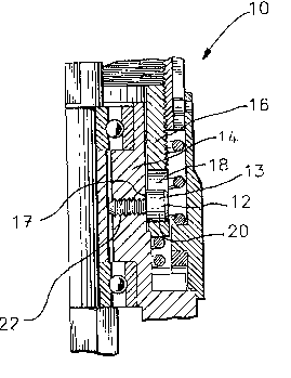
Figure 3 is side elevational view in partial section of the locking
system of the present invention.
To understand the present invention it is necessary to understand
the prior art. In rivet shavers 100 it is important that the adjustment
bushing 67 which positions the cutter not rotate with respect to the
shaft housing 60. In prior art rivet shavers this was typically
accomplished in one of two ways. The first method is shown in Figure 1.
Therein a dog point set screw 65 passes through bushing 67 into shaft
housing 60. The end 66 of set screw 65 enters a slot 63 in shaft
housing 60 which thus prevents rotation of the adjustment bushing 67
with respect to the housing 60. Because of the vibrations normally
associated with air tool use set screw 65 may back out and become lodged
in the cavity 71 between collar 73 and bushing 67. Once this happens
it becomes impossible to adjust or disassemble the rivet shaver.
_2_

._,
In Figure 2 a second prior art method of locking the adjustment
bushing 67 to shaft housing 60 in a rivet shaver using a Woodruff key 85
is shown, key 85 is press fit into shaft housing 60. If key 85
becomes loose it may become tilted arid prevent longitudinal movement of
the bushing 67 with respect to the housing 60. Such prevention of
movement will render the rivet shaver inoperative.
As shown in Figure 3 the locking system of the present invention 10
includes a cap screw 12 which is threaded into housing 14. Cap screw 12
is placed in tension. This accomplishes three things. First,
adjustment bushing 16 is rotationally locked in position with respect to
shaft housing 14 as the cap portion 13 of cap screw 12 fits within slot
18 formed in bushing 16. Secondly, the tension placed on cap screw 12
creates a frictional force, between the underside 15 of the cap screw
head 13 and the side 20 of housing 14. This frictional force tends to
keep the cap screw 12 in place. Thirdly, the complete insertion of cap
screw 12 into housing 14 results in an interference threaded fit of cap
screw 12 into the threaded hole 22 in shaft housing 14. This
interference fit occurs because in the space just under the head of
typical cap screws there is an imperfectly formed thread or a flat
~0 portion. When this imperfectly formed' thread or flat portion is
threaded into threaded hole 22 in shaft housing 14 an interference fit
occurs with the uppermost thread in threaded hole 22. It is this
interference fit which assists in retaining screw 12 in pcsitio'n.
According to the present invention there is provided a locking
system for a rivet shaver wherein the locking element is not free to
vibrate lose and thus jam the components within the rivet shaver.
_3_

Still other embodiments of the locking system of the present
invention will apparent of those of ordinary skill in the art once
having read the foregoing description and accompanying claims.

Representative Drawing
A single figure which represents the drawing illustrating the invention.
Administrative Status

2024-08-01:As part of the Next Generation Patents (NGP) transition, the Canadian Patents Database (CPD) now contains a more detailed Event History, which replicates the Event Log of our new back-office solution.

Please note that "Inactive:" events refers to events no longer in use in our new back-office solution.

For a clearer understanding of the status of the application/patent presented on this page, the site Disclaimer , as well as the definitions for Patent , Event History , Maintenance Fee  and Payment History  should be consulted.

Event History

Description Date
Time Limit for Reversal Expired 2009-07-13
Letter Sent 2008-07-14
Inactive: IPC from MCD 2006-03-11
Grant by Issuance 2000-10-17
Inactive: Cover page published 2000-10-16
Inactive: Final fee received 2000-07-13
Pre-grant 2000-07-13
Notice of Allowance is Issued 2000-01-21
Letter Sent 2000-01-21
Inactive: Approved for allowance (AFA) 2000-01-05
Amendment Received - Voluntary Amendment 1998-05-28
Inactive: Application prosecuted on TS as of Log entry date 1997-08-22
Letter Sent 1997-08-22
Inactive: Status info is complete as of Log entry date 1997-08-22
All Requirements for Examination Determined Compliant 1997-07-11
Request for Examination Requirements Determined Compliant 1997-07-11
Application Published (Open to Public Inspection) 1991-02-08

Abandonment History

There is no abandonment history.

Maintenance Fee

The last payment was received on 2000-06-29

Note : If the full payment has not been received on or before the date indicated, a further fee may be required which may be one of the following

  • the reinstatement fee;
  • the late payment fee; or
  • additional fee to reverse deemed expiry.

Patent fees are adjusted on the 1st of January every year. The amounts above are the current amounts if received by December 31 of the current year.
Please refer to the CIPO Patent Fees web page to see all current fee amounts.

Owners on Record

Note: Records showing the ownership history in alphabetical order.

Current Owners on Record
COOPER INDUSTRIES, INC.
Past Owners on Record
PHILIP A. SNIDER
Past Owners that do not appear in the "Owners on Record" listing will appear in other documentation within the application.
Documents

To view selected files, please enter reCAPTCHA code :


To view images, click a link in the Document Description column. To download the documents, select one or more checkboxes in the first column and then click the "Download Selected in PDF format (Zip Archive)" or the "Download Selected as Single PDF" button.

List of published and non-published patent-specific documents on the CPD .

If you have any difficulty accessing content, you can call the Client Service Centre at 1-866-997-1936 or send them an e-mail at CIPO Client Service Centre.


Document
Description 
Date
(yyyy-mm-dd) 
Number of pages   Size of Image (KB) 
Representative drawing 1998-07-05 1 12
Representative drawing 2000-09-18 1 16
Claims 1993-11-19 1 26
Drawings 1993-11-19 1 37
Description 1993-11-19 4 103
Abstract 1993-11-19 1 14
Acknowledgement of Request for Examination 1997-08-21 1 178
Commissioner's Notice - Application Found Allowable 2000-01-20 1 166
Maintenance Fee Notice 2008-08-24 1 171
Correspondence 1994-05-30 5 206
Correspondence 2000-07-12 1 34
Fees 1998-06-22 1 49
Fees 1999-06-27 1 35
Fees 1997-06-26 1 42
Fees 2000-06-28 1 35
Fees 1996-06-24 1 36
Fees 1995-06-29 1 32
Fees 1994-06-19 1 36
Fees 1993-05-27 1 27
Fees 1992-06-24 1 25