Note: Descriptions are shown in the official language in which they were submitted.
-- 1 --
HIGH EFFICIENCY TURBOEXPANDER
Technical Field
_ _ ~ _ _ _
This invention relates generally to the
field of turboexpansion whereby fluid is expanded to
produce useful work.
_ackqround Art
A high pressure fluid is often expanded,
i.e. reduced in pressure, through a turbine to
extract useful energy from the fluid and thus to
produce work. The high pressure fluid enters the
turbine and passes through a plurality of passages
defined by turbine blades which are mounted on an
impeller hub which in turn is mounted on a shaft.
The fluid enters the blade passages and causes
rotation of the impeller and ultimately leads to the
recovery of energy and to the production of work
from the spinning shaft.
It is desirable to operate the expansion
turbine with as high an efficiency as possible.
Since turboexpanders generally handle large volumes
of fluid, even a small increase in turbine efficiency
will have a significant impact on operating results.
Accordingly, it is an object of this
invention to provide an improved method for operating
25 a turboexpander to achieve increased efficiency over -
that attainable with known operating methods.
It is another object of this invention to
provide a high efficiency turboexpander having
increased efficiency over that attainable with known
turboexpanders. ~
~ '
D-16250
.;-- .. ,, .. : . : . : : ... - :.
-- 2
SummarY Of The Invention
The above and other objects which will
become apparent to one skilled in the art upon a
rea~ing of this disclosure are attained by the
present invention one aspect of which is:
A method for operating a turboexpander
having a rotatable assembly comprising a shaft, an
impeller hub mounted on the shaft, and a plurality
of blades on the impeller hub to form a plurality of
fluid flow paths, each fluid flow path defined by
the impeller hub surface and two adjacent blades,
said met~od comprising:
(A) passing fluid into a fluid flow pa~h at
an angle directed toward the leading edge of the
15 trailing blade of the two adjacent blades forming .
the fluid flow path; and
(B) passing the fluid through the fluid
flow path while maintaining the pressure normal to
the mean streamline of the fluid in the meridional
plane between the impeller hub surface and the
shroud surface substantially constant.
Another aspect of the present invention is:
A turboexpander having a rotatable assembly
comprising a shaft, an impeller hub mounted on the
shaft, and a plurality of blades on the impeller hub
to form a plurality of fluid flow channels, each
fluid flow channel defined by the impeller hub
surface and two adjacent blades, characterized by:
(A) means to provide fluid into a fluid
flow channel at an angle directed toward the leading
edge of the trailing blade of the two adjacent
blades forming the fluid flow channel; and
(B) the impeller hub and the two adjacent
D-16250
-. , :, , - .............. - - : :,. : .............. .
., ,, , , ., ~ , ~. . . . .
- 3 ~ ~ ~2i~
blade surfaces forming the fluid flow channel being
contoured so that as a fluid element moves through
the fluid flow channel along the mean streamline,
the sum of t~e forces on the element normal to the
streamline in the meridional plane is about zero.
As used herein, the term "turboexpander
efficiency'` means the ratio of the actual to the
ideal enthalpy difference between the inlet and the
outlet conditions of the turboexpander.
As used herein, the term "mean streamline"
means the fluid flow path line which connects the
midpoints of the fluid flow channel along the fluid
flow path.
As used herein, the term "meridional plane"
means any plane that contains a point on the mean
streamline of the fluid flow and the centerline of
the impeller shaft.
As used herein, the term "substantially
constant" means within plus or minus 10 percent,
preferably within plus or minus 5 percent.
Brief DescriPtion Of The Drawinqs
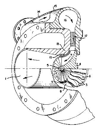
Figure 1 is a simplified illustration in
cross-section showing a turboexpander which may be
used to carry out this invention.
Figure 2 is an inlet velocity diagram illus-
trating the negative incidence of this invention.
Detailed Description
The invention will be described in detail
with reference to the Drawings.
Referring now to Figure 1, fluid 14, such
as nitrogen gas, at an elevated pressure is passed .
:
D-16250
, .. . - . - . - . -. , . , - .-, - . . - ., . ; - . , .. . ,.: . ., , .. -
, . , ., , . .. j .... , . ,,, ,- .. . , , ,,,: .. , . ~ ..
" ~ - , -, - - , " , : : :: . : - . .:
t.Vhih~
into and through turboexpander 15 and into the
rotatable assembly. The fluid inlet chamber 16 may
be a volute or plenum that directs the fluid to
inlet nozzles 17. The rotatable assembly comprises
shaft 5 and impeller hub 4 mounted on shaft 5. A
plurality of curved blades 6 are mounted on impeller
hub 4 and, in this arrangement, shroud 8 covers the
blades. The arrangement results in a plurality of
fluid flow paths 3 defined by the impeller hub
surface, the shroud inner surface and two adjacent
blades. Shrouded impellers, as illustrated in
Figure 1, typically utilize a labyrinth seal 9 with
seal face member 10 to prevent fluid bypass of the
rotating assembly. Non-shrouded or open impellers
can be utilized with this invention and would
utilize blade contours closely fitted to the
stationary housing 18. In the case of non-shrouded
or open impellers, the stationary housing surface
would be equivalent to the shroud surface and thus
the plurality of fluid flow paths would be defined
by the impeller hub surface, the housing inner
surface and two adjacent blades.
Fluid passes through the curved flow paths
as illustrated by arrow 7. As the fluid passes
through the flow paths the volume along the flow
path increases and the fluid is expanded. In the
course of this expansion the fluid pressure is
reduced by momentum transfer onto blades 6. This
energy exchange causes the rotatable assembly to
rotate. The shaft is connected to means which uses
energy such as compressor or generator. In this way
useful work is transferred from turboexpander flow
to, for example, compressor operation. The expanded
D-16250
~ lh~
fluid is passed out of turboexpander 15 as
illustrated by arrows 1. Typically the fluid is
expanded from a pressure within the range of about
300 to 800 psia to a pressure within the range of
about 15 to 100 psia.
The fluid is passed through the flow
passages in a pressure balanced manner wherein the
pressure normal to the mean streamline in the
meridional pl~ne between the impeller hub surface
and the shroud surface is kept substantially
constant. One way of maintaining the pressure
normal to the mean streamline substantially constant
is to provide a turboexpander having flow passage
contours which balance the forces on a fluid element
including the centrifugal force due to wheel
rotation, the centrifugal force due to the curved
trajectory of the element, the coriolis force due to
the movement in a moving coordinate system and the
force due to changes in momentum such that the sum
of these forces on a fluid element is about zero as
it moves along a pressure balanced flow mean
streamline in the meridional plane. A flow path
where the forces on a fluid element are balanced as
described above is commonly referred to as a
pressure balanced flow path. Those skilled in the
art of turboexpansion are familiar with the concept
of a pressure balanced flow path and the conditions
under which pressure balanced flow is attained. A
particularly useful and comprehensive text
describing turbomachinery in general, and pressure
balanced flow paths in particular, is Turbomachines,
O.E. Balje, John Wiley ~ Sons, New York 1981,
particularly chapter 6.
D-16250
-- 6 --
The invention comprises the discovery that
if high pressure fluid is introduced into the fluid
flow paths at a defined negative angle and then
passed through the fluid flow paths while
maintaining the fluid pressure normal to the mean
streamline in the meridional plane substantially
constant, an unexpected increase in turboexpander
efficiency is attained.
This defined negative angle will now be
described with reference to Figure 2. In Figure 2
there is shown a simplified diagram of an impeller
wheel 20 having blades 21, 22 and 23. Adjacent
blades 21 and 22 form the sidewalls of flow p~h 24
and adjacent blades 22 and 23 form the sidewalls of
flow path 25. Assuming impeller wheel 20 rotates in
a clockwise direction 26, blade 23 is the leading
blade and blade 22 is the trailing blade of flow
path or flow channel 25. Similarly blade 22 is the
leading blade and blade 21 is the trailing blade of
flow path or flow channel 24. The right side of
each blade is the leading edge and the left side of
each blade is the trailing edge.
Elevated pressure fluid is passed into the
rotatable assembly at a certain absolute velocity
illustrated in Figure 2 by the vector C2. This
vector C2 can be resolved as shown in Figure 2
into the vectors W2 and U2. U2 represents the
tangential impeller velocity at the point where the
fluid enters the rotatable assembly. W2 represents
the fluid velocity relative to the impeller
surfaces. Vector W2 forms an angle A2 with the
line 27 which represents the theoretical extension
of blade 22. This angle A2, known as the relative
~-16250
- : , ., . : , - - " . "- " . ,, , . ~ , ., .. .; ., ~, .. .. .
, ~ . . :., : . . .: , . - . . . - , , : . . .: . - ..
flow angle, represents the angle between the fluid
flow and the blades.
In the practice of this invention, at the
design point elevated pressure fluid is introduced
into the rotatable assembly of a turboexpander with
an absolute velocity such that the angle between the
fluid flow and the blades is negative. In other
words the elevated pressure fluid flowing into a
flow path does so at an angle directed toward the
leading edge of the trailing blade of the two
adjacent blades forming that flow path. Preferably
this incidence angle is within the range of from -
10 to - 40 degrees.
The desired negative incidence inlet flow
is attained by adjusting the inlet nozzles 17 shown
in Figure 1. It should be noted that the invention
is preferably utilized with substantially no fluid
swirl at the outlet of the turbine impeller. This
means that the blade exit angle must be such that
t'le fluid exiting into diffuser 1 has essentially
zero tangential velocity.
The following Example and Comparative
Examples are presented to further illustrate the
invention or to demonstrate the improved efficiency
attainable by use of the method of this invention.
They are not intended to be limiting.
EXAMPLE
Gaseous nitrogen at a pressure of from
about 500 to 650 pounds per square inch absolute
(psia) was expanded by passage through a
turboexpander of this invention to a pressure of
from about 70 to 90 psia. The expansion caused the
D-16250
' : .
,. ' ' ':
- 8 -
rotatable assembly of the turboexpander to rotate at
about 23,000 revolutions per minute (rpm). The
fluid passed throuqh each flow path while the
pressure normal to the mean streamli~e in the
meridional plane of that flow path was substantially
constant and the fluid exited from the impeller with
substantially zero swirl. The f~id was passed into
the rotatable assembly at ~n absolute velocity and
direction which caused the fluid to h~ve an
incidence angle of about -15 degrees. The
turboexpander was operated until steady state
conditions were reached and the efficiency was
measured.
COMPARATIVE EXAMPLE 1
lS For comparative purposes a procedure
similar to that described in the Example was carried
out except that the turboexpander design and the
fluid absolute velocity and direction resulted in an
incidence angle of about 0 degrees. The measured
efficiency of the turboexpander was 1.7 percentage
points less than that achieved in the Example.
COMPARATIVE EXAMPLE 2
For comparative purposes a procedure
similar to that described in the Example was carried
out except that the turboexpander design and the
fluid absolute velocity and direction resulted in an
incidence angle of about +11 degrees. The measured
efficiency of the turboexpander was 2.5 percentage
points less than that achieved in the Example.
It is thus demonstrated that the method and
apparatus of this invention enables an increase in
D-16250
~ ~ 2 ~
turboexpander efficiency over that attainable when
the invention is not employed.
It is surprising that such an efficiency
increase is attained. Heretofore it has been the
conventional thinking in the turboexpander art that
when fluid is expanded through a turboexpander in a
pressure balanced flow path, the fluid angle of
incidence with the blades should be about 0
degrees. This is because such a zero incidence
injection would cause the fluid to become aligned
with the blades within the flow channels in the . :
shortest possible time thus reducing swirls, eddy
currents and other fluid flow behavior wi~hin the
flow channels which would detract from turboexpander
efficiency
While not wishing to be held to any theory,
applicant believes that the unexpected increase in ~
turboexpander efficiency attained when the fluid is ~.
passed into the flow paths at a negative incidence
angle and expanded through the flow paths in a
pressure balanced manner may be explained as follows.
Since the blades have a defined or non-zero
thickness the fluid passing into the rotatable
assembly is confined in volume by the blade volume.
The fluid flow is thus disturbed by this contraction
caused by the leading blade thickness. This -~
disturbance results in an efficiency penalty.
However, if the fluid is introduced into the ~.
rotatable assembly at a negative incidence angle, - ~-
30 i.e. directed toward the leading edge of the trailing ~ -
blade, the fluid flow is divided, the disturbance
discussed above is reduced, and the fluid most
closely follows the path intended by the designer. :
D-16250
.:
- 10 -
~3
Now by the use of this invention one can
carry out turboexpansion with an efficiency higher
than that heretofore attainable. While the
invention has been described in detail with
reference to a certain embodiment it will be
understood that there are other embodiments of this
invention within the spirit and scope of the claims.
D-16250