Language selection

Search

Patent 2021997 Summary

Third-party information liability

Some of the information on this Web page has been provided by external sources. The Government of Canada is not responsible for the accuracy, reliability or currency of the information supplied by external sources. Users wishing to rely upon this information should consult directly with the source of the information. Content provided by external sources is not subject to official languages, privacy and accessibility requirements.

Claims and Abstract availability

Any discrepancies in the text and image of the Claims and Abstract are due to differing posting times. Text of the Claims and Abstract are posted:

  • At the time the application is open to public inspection;
  • At the time of issue of the patent (grant).
(12) Patent: (11) CA 2021997
(54) English Title: BLOCK FOR CONCRETE WALL FORM CONSTRUCTION
(54) French Title: BLOC DE BETON POUR LA CONSTRUCTION DE MUR
Status: Term Expired - Post Grant Beyond Limit
Bibliographic Data
(51) International Patent Classification (IPC):
  • E04G 11/06 (2006.01)
  • E04B 02/02 (2006.01)
  • E04B 02/26 (2006.01)
  • E04C 02/20 (2006.01)
(72) Inventors :
  • HOLLAND, GEARY C. (United States of America)
  • ALLISON, CHARLES E. (United States of America)
(73) Owners :
  • PERMA-FORM ENTERPRISES, INC.
  • REAL SOLUTIONS TECHNOLOGIES DE MEXICO, S.A. DE C.V.
(71) Applicants :
  • PERMA-FORM ENTERPRISES, INC. (United States of America)
  • REAL SOLUTIONS TECHNOLOGIES DE MEXICO, S.A. DE C.V. (Mexico)
(74) Agent: SMART & BIGGAR LP
(74) Associate agent:
(45) Issued: 2001-10-30
(22) Filed Date: 1990-07-26
(41) Open to Public Inspection: 1991-10-27
Examination requested: 1997-07-04
Availability of licence: N/A
Dedicated to the Public: N/A
(25) Language of filing: English

Patent Cooperation Treaty (PCT): No

(30) Application Priority Data:
Application No. Country/Territory Date
514,734 (United States of America) 1990-04-26

Abstracts

English Abstract


This invention provides a block to be used with the block
means of similar character to create a form for a concrete wall.
The blocks are of lightweight plastic and are of substantially
rectangular shape, and have opposite ends, opposite sides, upper
and lower interlocking surfaces, a substantially hollow interior
compartment, and opposite end walls and opposite side walls. The
upper interlocking surfaces comprise an elongated longitudinal
rib having a rectangular bass and an inverted V-shaped upper
surface. These ribs have a width less than that of the side
walls, and have a substantially horizontal ledge adjacent either
side thereof. Lateral extending ribs spaced from each other
extend across the ledges and ribs. The lateral extending ribs
also have an inverted V-shaped upper surface which extends from a
lower rectangular base portion. A plurality of cylindrical plugs
extend upwardly in spaced relation from the ribs. The lower
interlocking surface is a mere image of the upper interlocking
surface. Spanner ribs with a U-shaped notch in the upper portion
thereof extend through the interior compartment of the block.
The notches are adapted to receive an elongated reinforcing rod.
The ends of the blocks have U-shaped openings into which a U-
shaped plug can be inserted in locked condition to dam off the
end of the block which appears at the end of the concrete wall to
be poured.


Claims

Note: Claims are shown in the official language in which they were submitted.

CLAIMS:
1. A block means to be used with block means of similar character to create a
form
for a concrete wall, comprising:
a block of substantially rectangular shape having opposite ends, opposite
sides, an
upper interlocking surface, a lower interlocking surface, a substantially
hollow interior compartment, opposite end walls, and opposite side walls;
said upper interlocking surface comprising an elongated longitudinal first rib
on
each of the upper surfaces of said side walls, and extending along the
length of said side walls;
said ribs having a width less than that of side walls;
a substantially horizontal ledge adjacent at least one side of each of said
ribs;
spaced apart laterally extending interlocking surface means comprising
intersecting ribs extending completely across the upper surfaces of said
side walls and intersecting said ledges and said first ribs;
said lower interlocking surface comprising a mirror image of said upper
interlocking surface;
said first ribs and said intersecting ribs have an upper surface comprised of
an
inverted V-shaped;
a plurality of cylindrical plugs extending upwardly at the intersection of
said first
ribs and said intersecting ribs.

2. The block means of claim 1 wherein said laterally extending interlocking
surface
means have a rectangular base portion.
3. The block means of claim 1 wherein a plurality of spanner ribs extend
laterally
across said interior compartment between said side walls, with each of said
spanner ribs
having a notch means to receive and support an elongated reinforcing rod.
4. The block means of claims 1, 2 or 3 wherein said block is comprised of a
lightweight plastic material.
5. The block means of claim 1 wherein said plastic material is expanded
polystyrene.
6. The block of claim 1 wherein one of said end walls have oppositely disposed
upper and lower U-shaped openings and a central spanner rib portion in
alignment with
said spanner ribs.
7. The block of claim 6 wherein a U-shaped plug is locked into one of said U-
shaped
openings.
8. The block means of claim 1 wherein said block is stacked in interlocking
relation
with a plurality of other like blocks to form an elongated wall section, with
said wall
comprising a plurality of courses of blocks, with each course of blocks
comprising a
plurality of blocks laid in end to end relationship, and with the lower
interlocking surfaces
of the blocks in the upper adjacent course of blocks.
9. The block means of claim 8 wherein the blocks of each course of blocks
longitudinally overlap at least two blocks in adjacent courses of blocks.

10. The block means of claims 8 or 9 wherein hardened concrete is located
within the
interior compartments of the blocks in each course of blocks.
11. The block means of claim 10 wherein elongated reinforcing rods extend
longitudinally through each course of blocks.
12. The block means of claims 8, 9, 10 or 11 wherein the material of said
block is
lightweight plastic material.

Description

Note: Descriptions are shown in the official language in which they were submitted.


~~2~.~~~~'~
BACKGROUND OF THE INVENTION
Hollow plastic blocks with interlocking upper and lower
surfaces have been used in the past for assembly into a wall
structure to serve as a form for plastic concrete. The blocks
serve essentially as the form for the concrete and provide no
structural strength ~o the structure after the concrete has set.
The blocks thereafter do provide permanent insulation, sound
attenuation, and further facilitate the installation of electric,
gas and water conduits.
Existing blocks used for the foregoing purposes often cannot
maintain the poured concrete wall in straight condition, or
cannot permit the pouring of a wall of any substantial height.
This was because the interlocking surfaces of the blocks are
inadequate to maintain the great weight of the plastic concrete.
The assembled plastic form blocks often move to a condition of
disalignment, and sometimes fail altogether before the concrete
has set.
Therefore, the principal object of this invention is to
provide a block for concrete wall fo::m construction which will
permit substantial interlocking surfaces with adjacent blocks to
permit the forming for concrete walls of substantial length and
height, and which will maintain the proper alignment thereof.
A further object of this invention is to provide a block for
concrete wall form construction which has an increased interlock
ing surface to strengthen the assemblage with like blocks to
create a form for a poured concrete wall.
i

A still further object of this invention is to provide a
block for concrete wall form construction which will easily
accammodate elongated lengths of reinforcing steel.
A still further object of this invention is to provide a
block for concrete wall form construction which has indices means
on the outside surface thereof to permit the insertion of utility
lines and boxes. °
These and other objects will be apparent to those skilled in
the art.
BRIEF SUMMARx OF THE INVENTION
This invention provides a block to be used with the block
means of similar character to create a form for a concrete wall.
The blocks are of lightweight plastic and are of substantially
rectangular shape, and have opposite ends, opposite sides, upper
and lower interlocking surfaces, a substantially hollow interior
compartment, and opposite end walls and opposite side walls. The
upper interlocking surfaces comprise an elongated longitudinal
rib having a rectangular base and an inverted V-shaped upper
surface. These ribs have a width less than that of the side
walls, and have a substantially hori~antal ledge adjacent either
side thereof. Lateral extending ribs spaced from each other
extend across the ledges and ribs. The laterally extending ribs
also have an inverted V-~shaPed uPPex surface which extends from a
lower rectangular base portion~ A plurality of cylindrical plugs
extend upwardly in spaced relation from the ribs. The lower

r~~~~.~~:~>3
interlocking surface is a mirror image of the upper interlocking
surface.
Spanner ribs with a U-shaped notch in the upper portion
thereof extend through the interior compartment of the block.
The notches are adapted to receive an elongated reinforcing rod.
The ends of the,blocks have U-shaped openings into which a
U-shaped plug can be inserted in locked condition to dam aff the
end of the block which appears at the end of the concrete wall to
be poured.
BRIEF DESCRIPTTON OF THE DRAWIIdOS
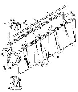
Fig. Z is an exploded perspective view of the block of this
invention showing a reinforcing rod and the plugs which can be
inserted into the U-shaped openings at the end of a block which
appears at the end of the concrete form; ,
Fig. 2 is an exploded view of the left-hand end of Fig. 1 at
a smaller scale;
Fig. 3 is a top plan view at a reduced scale of the device
of Fig. 1;
Fig. 4 is a side elevational view of the block of Fig. 3;
Fig. 5 is a partial plan view taken an line 5-5 of Fig. 3;
Fig. 6 is a partial perspective view of the upper and lower
interlocking surfaces of the black;
Fig. 7 is a partial elevational view taken on line 7-7 of
Fig. 6;
Fig. B is a sectional view taken on line 8-8 of Fig. 6; and
- 4 -

s~g,~.~ ~~~~v
~~r:'~i.~. ~.9~ ya
Fig. 9 is a perspective view of two intersecting concrete
wall forms made in accordance with this invention and incorporat-
ing a plurality of the blocks of this invention.
DESCRIPTION OF THE PREFERRED EMBODIMENT
Block 1Q is comprised of a lightweight plastic material,
preferably of flameproof construction. A typical material is
E.P.S. Modified Bead, F-Grade, F-554 produced by Huntsman Chemi-
cal, Rome, Georgia. Block 14 has ends 12 and end walls 12A;
sides 14 and side walls 14A; upper and lower interlocking surfac-
es 16 and 18, respectively; and a hollow interior compartment 20.
Spanner ribs 22 extend across the hollow interior compartment 20
and join side walls 14A. The spanner ribs have a height less
than that of the side walls.
A U-shaped opening appears in each of the end walls 12A. A
lock grove 26 extends around the periphery of the U-shaped open-
ings 24. A U-shaped p~.ug 28 with a locking flange 3D adapted to
be inserted into the lock groves 26 are adapted to close the U-
shaaed openings 24 when it is desired to dam off the interior
compartment 20. U-shaped plugs 28 are normally used at the end
of the concrete form to be constructed.
Shallow score lines 32 are formed in the outer sides 14 of
block 10 directly opposite the ends of the spannex ribs 22. The
score lines 32 merely locate the position of the spanner ribs to
permit electrical boxes, arid various utility lines and connec-
tions to be placed in suitable cutout portions of the block and
the spanner ribs 22.

~~~~.~'~~~
notches 34 are formed in the uPPer Portions of the spanner
2 and the end walls 12A to receive and position elongated
ribs 2
reinforcing rods 36.
a er interlocking surface 16 comprises an elongated rib
The PP
which extends along the top of each of the side walls 14A
38
er ortion of: rib 38 is comprised of an inverted ~-shaped
The uPP p
surface 40 which is above a rectangular shaped base 42~ Trans--
erse ribs 44 are spaced apart and extend across ribs 38. The
v
ansverse ribs 44 also emerge from a rectangular base 42~ The
tr
transverse ribs 44 also intersect ledges 4~ which are substan°
1 horizontal and extend along the lateral sides of ribs 38.
tial y
drical plugs 50 emerge from the intersection of ribs 38 and
Cylin
nsverse ribs 44, and extend a slight distance above the ribs
tra
as best shown in Fig. 8.
As seen in Fig. 6, the lower interlocking surface is a
o~ image of the upper interlocking surface 16. Further, the
miry
et of the upper and lower interlocking surfaces 16 and 18
symm z=Y
ermit various of the blocks 10 to be stacked in overlapping
P
'tion so that any of the transverse ribs 44 and cylindrical
pose
can be received in the corresponding mirror image por-
plugs 50
dons of any lower interlocking surface.
It should be noted that the upper end plug 2g in Fig. 1 has
an interlocking surface similar to the configuration of uPPer
ocking surface 16. The interlocking surface appearing at
interl
m lug 28 in Fig. Z has a mirror image of the interlock°
the botto P
ing surface of the upper Plug 28'
°

~~?~~~2
Fig. 9 shows a plurality of the blocks 10 arranged in the
intersection of two wall forms 52. Each wall 52 is comprised of
courses of blocks 54, 56, 58 and 60. It is seen that the plugs
28 are inserted as described above at the corner 62 of the inter-
secting walls. It should.also be noted that the individual
blocks 10 in Fig. 9 a.re overlapped with respect to the blocks in
the adjacent courses. The reinforcing rods 36 are positioned in
the notches 34 as the walls 52 are being assembled from the
individual blocks.
After the form of Fig. 9 has been created to create the
complete wall form of a given height, plastic concrete (not
shown) is poured into the hollow interior compartments 20 of the
blocks through the uppermost course. The upper and lower inter°
locking surfaces l6 and 1B maintain the individual blocks 10 in
rigid connection with each other ~o maintain the plastic concrete
until the concrete hardens. The plastic blocks remain intact and
can be used for insulation purposes. By using the score lines
32, electricians, for example, can dig away some of the plast=c
material and insert an electrical box in the cutout portion of
the blocks 10. A conduit can be extended completely through the
wall by inserting a hole in one of the spanner ribs 22. If
desired, some utility limes can be inserted iota the wall farm
before the concrete is poured.
The interlocking surfaces 16 and 18 present substantially
more interlocking surfaces than existing blocks, and as a result,
the blocks of this invention are much better able to serve their
_ 7 _

~~~~.~~'~~
intended purpose than those of the prior art. It is therefore
seen that this invention will achieve at least its stated ob~ee-
tives.
g _

Representative Drawing
A single figure which represents the drawing illustrating the invention.
Administrative Status

2024-08-01:As part of the Next Generation Patents (NGP) transition, the Canadian Patents Database (CPD) now contains a more detailed Event History, which replicates the Event Log of our new back-office solution.

Please note that "Inactive:" events refers to events no longer in use in our new back-office solution.

For a clearer understanding of the status of the application/patent presented on this page, the site Disclaimer , as well as the definitions for Patent , Event History , Maintenance Fee  and Payment History  should be consulted.

Event History

Description Date
Inactive: Expired (new Act pat) 2010-07-26
Letter Sent 2010-02-24
Inactive: Single transfer 2010-02-03
Inactive: Late MF processed 2009-08-05
Letter Sent 2009-07-27
Inactive: Office letter 2007-05-23
Inactive: Corrective payment - s.78.6 Act 2007-02-01
Inactive: IPC from MCD 2006-03-11
Inactive: Entity size changed 2003-07-08
Grant by Issuance 2001-10-30
Inactive: Cover page published 2001-10-29
Inactive: Entity size changed 2001-08-23
Inactive: Final fee received 2001-07-23
Pre-grant 2001-07-23
Letter Sent 2001-04-10
Notice of Allowance is Issued 2001-04-10
Inactive: Received pages at allowance 2001-04-02
Inactive: Office letter 2001-01-04
Inactive: Approved for allowance (AFA) 2000-11-30
Amendment Received - Voluntary Amendment 2000-10-02
Inactive: S.30(2) Rules - Examiner requisition 2000-03-31
Amendment Received - Voluntary Amendment 1997-11-07
Letter Sent 1997-08-19
Inactive: Status info is complete as of Log entry date 1997-08-14
Inactive: Application prosecuted on TS as of Log entry date 1997-08-14
All Requirements for Examination Determined Compliant 1997-07-04
Request for Examination Requirements Determined Compliant 1997-07-04
Application Published (Open to Public Inspection) 1991-10-27

Abandonment History

There is no abandonment history.

Maintenance Fee

The last payment was received on 2001-07-25

Note : If the full payment has not been received on or before the date indicated, a further fee may be required which may be one of the following

  • the reinstatement fee;
  • the late payment fee; or
  • additional fee to reverse deemed expiry.

Patent fees are adjusted on the 1st of January every year. The amounts above are the current amounts if received by December 31 of the current year.
Please refer to the CIPO Patent Fees web page to see all current fee amounts.

Owners on Record

Note: Records showing the ownership history in alphabetical order.

Current Owners on Record
PERMA-FORM ENTERPRISES, INC.
REAL SOLUTIONS TECHNOLOGIES DE MEXICO, S.A. DE C.V.
Past Owners on Record
CHARLES E. ALLISON
GEARY C. HOLLAND
Past Owners that do not appear in the "Owners on Record" listing will appear in other documentation within the application.
Documents

To view selected files, please enter reCAPTCHA code :


To view images, click a link in the Document Description column (Temporarily unavailable). To download the documents, select one or more checkboxes in the first column and then click the "Download Selected in PDF format (Zip Archive)" or the "Download Selected as Single PDF" button.

List of published and non-published patent-specific documents on the CPD .

If you have any difficulty accessing content, you can call the Client Service Centre at 1-866-997-1936 or send them an e-mail at CIPO Client Service Centre.

({010=All Documents, 020=As Filed, 030=As Open to Public Inspection, 040=At Issuance, 050=Examination, 060=Incoming Correspondence, 070=Miscellaneous, 080=Outgoing Correspondence, 090=Payment})


Document
Description 
Date
(yyyy-mm-dd) 
Number of pages   Size of Image (KB) 
Claims 2001-04-09 3 73
Representative drawing 2001-10-02 1 19
Abstract 1994-02-04 1 36
Drawings 1994-02-04 3 173
Claims 1994-02-04 4 90
Description 1994-02-04 7 232
Representative drawing 1999-07-11 1 38
Claims 2000-10-01 2 75
Acknowledgement of Request for Examination 1997-08-18 1 178
Commissioner's Notice - Application Found Allowable 2001-04-09 1 163
Maintenance Fee Notice 2009-08-24 1 170
Late Payment Acknowledgement 2009-08-24 1 163
Courtesy - Certificate of registration (related document(s)) 2010-02-23 1 103
Fees 2002-07-14 1 30
Fees 2002-07-14 1 27
Correspondence 2001-07-22 1 41
Fees 2001-07-24 1 44
Correspondence 2001-04-01 4 115
Fees 1997-07-03 1 31
Fees 1999-07-22 1 28
Correspondence 2007-05-22 1 14
Fees 2009-08-04 1 24
Fees 1996-07-10 1 31
Fees 1995-07-09 1 33
Fees 1994-07-13 1 28
Fees 1993-07-22 1 24
Fees 1992-07-19 1 20