Note: Descriptions are shown in the official language in which they were submitted.
~02~~049
FN 93677 CAN lA
DIFFRACTIVE LENS
Field of the Invention ,
The present invention relates to lenses having
diffractive power.
Background of the Invention
Refraction is the well-known phenomenon whereby .~
light changes direction when passing from a medium having
a first index of refraction to one having a second index
of refraction unless the beam of light strikes the
interface between the two media perpendicular to that
interface. Traditional lenses operate because of
refraction. Such lenses, operating by refraction, have
been known for many years.
It is also possible to construct lenses
operating due to the principle of diffraction.
Diffractive lenses, while of more recent origin than
refractive lenses, still have been known for over one
hundred years. Diffractive lenses are very sensitive to
the wavelength of the light striking them. Furthermore
they require that the sizes of the di,ffractive regions be
very precisely manufactured. Therefore diffractive lenses
were not in significant usage until recently. With the
advent of good monochrome light sources, such as lasers
and light emitting diodes, and precise machining and
replication techniques, diffractive lenses have become
more important.
One type of diffractive lens is sometimes called
a kinoform. In such a lens the diffractive zones are
formed as a series of structures on a surface of the .lens.
2022~4~
_2_
These structures can be formed in a variety of ways. They
may be etched using a photolithographic process, they may
be directly lathe cut in the sur:Eace of the lens, or a
master may be manufactured from which the lenses are
manufactured using known techniques such as injection
molding. Alternatively the structures may be formed at
the interface of two materials with different indices of
refraction in order to construct a kinoform with smooth
outer surfaces. Similarly the structures may be formed by
introducing a dopant that alters the index of refraction
into selected regions of the lens substrate.
In order for the lens to operate properly the
sizes of the zones must be very precisely contrblled.
Because the zone widths are smaller in the zones farther
from the optical axis of the lens, it is often hard to
form the outer zones. This problem is particularly
pronounced in "fast" lenses, i.e. those designed to
operate at a high aperture to focal distance ratio. In
such lenses the outer zones are very narrow.
Summary of the Invention
In the invention, a lens has diffractive power
produced by diffractive zones. The zones are terminated
by optical steps. A first group of zones has optical
steps having optical heights equal to j~ and a second
group of zones has optical steps equal to k~ where ~ is a ..
design wavelength of light of the lens and j and k are
unequal nonzero integers. Alternatively, the invention
may be described as a lens having diffractive power
produced by diffractive zones where a first group of zones
has optical steps having optical heights such that a step
will produce a relative phase shift equal to 2jn at a
point on the optical axis at a distance from the lens
equal to the back focal distance between two light rays of
the design wavelength of the lens emanating from a point
source on the optic axis of the lens at a distance equal
~~~204~
-
to the front focal distance of the lens from the lens and
striking the lens immediately on opposite sides of the
optical step. The lens further has a group of zones
having optical steps having optical heights such that a
step will produce a relative phase shift of 2kn at a point
on the optical axis at a distance from the lens equal to
the back focal distance between two light rays of the
design wavelength of the lens emanating from a point
source on the optical axis of the lens at a distance equal
to the front focal distance of the lens from the lens and
striking the lens immediately on opposite sides of the
step. In this formulation, j and k are unequal nonzero
integers.
Brief Description ',
of the Drawings
Figure 1 is a schematic cross-sectional view of
a prior art kinoform;
Figure 2 is a schematic cross-sectional view of
a diffractive lens according to the invention;
Figure 3 is a schematic cross-sectional view of
a diffractive lens according to a different embodiment of
the invention;
Figure 4 is a schematic front view of a lens
according to the invention; and
Figure 5 is a schematic front view of a lens
according to a different embodiment of the invention.
Detailed Description
of a Preferred Embodiment
Diffractive lenses typically use diffractive
zones that are either linear or circular. Lenses using
linear or rectangular zones have focal characteristics
similar to those of a cylindrical refractive lens.
Diffractive lenses utilizing concentric circular zones
~~220~~
-4-
have focal characteristics similar to those of a spherical
refractive lens. The present invention will be described
in the context of such lenses utilizing linear or circular
zones. Those skilled in the art, however, will recognize
that these zones could be elliptical or even of arbitrary
shape. The effect is simply that the focal length would
vary along different radii of the lens.
Figure 1 shows a kinoform 10 of the prior art.
It is important to note that the nature of dfffractive
optics makes it necessary to design a lens with a specific
front conjugate point and a specific back conjugate point,
unlike the more familiar spherical refractive optics in
which moving the front conjugate point will simply move
the back conjugate point. in the case of diffractive
optics moving the front conjugate point will generally
degrade performance quite rapidly. The lens of Figure 1
is a collimator. A collimator is a special case where the
front conjugate point is at a finite distance from the
lens, the front focal distance, while the back conjugate
point is at an infinite distance. The invention will be
described with respect to collimators, although those
skilled in the art will recognize that the front focal
distance could be infinite and the back focal distance
finite or both focal distances could be finite within the
scope of the invention.
In Figure 1 diffractive lens 10 has a smooth
side 12 and a structured side 14. As shown, structured
side 14 is designed to be the first surface, i.e. the
surface struck by the in-coming light, although kinoforms
in which the structured surface is the second surface are
also known. As will be explained, the size of the
structures on structured surface 14 is determined by the
intended focal length of the lens, the relative indices of
refraction of the lens and the surrounding media, and the
wavelength of the light for which the lens is designed,
often known as the design wavelength.
2~2~049
-5-
The lens of Figure 1 will be described with
respect to light emanating from a point source at the
front focal distance from the lens. Since lens 10 is a
collimator such light would emerge from the lens
collimated. Lens 10 has a smooth surface, 12, and a
structured surface 14. Light rays 16, 18, and 20 emanate
from a point 22. Light ray 16 strikes structured surface
14 at point 24. Light ray 16 travels along the optic axis
of lens 10. Normally this would be at the center of the
lens but nothing prevents the lens from being asymmetric
and having the optic axis at another location. Structured
surface 14 follows a smooth curve 26 from point 24 to
point 28. Curve 26 is designed such that, if the distance
from point 22 to point 24 is equal to the front foca1
distance of the lens, the optical path length from point
22 through any point on curve 26 to surface 12 will be
equal. More generally the optical path length from the
front conjugate point through the lens, to the back
conjugate point should be constant, but, since in Figure 1
the back conjugate point is at infinity, the distance
after the light emerges from lens 10 may be ignored.
Using light ray 18 as an example, the optical path length
is defined a~s (lzz x n2) + (146 x nl) where 12z is the
distance from point 22 to point 44, 146 is the distance
from point 44 to point 46, nl is the index of refraction
of the lens and n2 is the index of refraction of the
surrounding medium. Point 28 is chosen such that an
optical step 30 may be provided where optical step 30 has
an optical height equal to the design wavelength of the
lens and the lens has the same thickness after the optical.
step as it had at point 24. For these purposes optica1
height is defined as h x (nl-n2) where h is the actual
physical height of the step, nl is the index of refraction
of the material of lens 10 and n2 is the index of
refraction of the surrounding medium.
More generally optical step 30 does not
necessarily cause lens 10 to have the same thickness after
step 30 as it had at point 24. This is because the lens
~0~2040
-6-
may have a refractive power in addition to its diffractive
power. In order to provide such a refractive power,
surface 12 may be curved. Alternatively the structures of
surface 14 may be superposed on a smooth curve or such '
superposition may occur in conjunction with a curvature of
surface 12. Thus, in general, the actual contour of
surface 14 deviates from the underlying curve over the
width of each diffractive zone arid returns to the
underlying curve at the optical steps. Lens 10 is then a
special case in which the underlying curve has an infinite
radius of curvature, i.e., is a plane surface.
The statement that the optical steps have
optical heights of one wavelength is actually an
approximation, although normally a very good one.
Actually, the optical steps should be of a size that will
produce a relative phase shift of 2rt at the back conjugate
point (i.e., one wavelength) between light rays of the
design wavelength emanating from a point source on the
optical axis at a distance equal to the front focal
distance from the lens and striking the lens immediately
on opposite sides of the step. For these purposes it
should be noted that the back conjugate point is a point
on the optical axis at a distance from the lens equal to
the back focal distance. As the angle between the optical
axis of the lens and the line connecting the front
conjugate point with the step increases, a correction to
the optical height of the step based on trigonometric
considerations must be introduced. This requirement is
most relevant to lenses designed to operate with a very
large aperture to focal distance ratio. The term focal
distance is used here without reference to the front or
back focal distance because the ratios of the aperture to
both focal distances are important.
In order to achieve the constant optical
distance described above, curve 26 should preferably be
hyperbolic. If so the zone is said to have a hyperbolic
contour. In many circumstances, however, a circular curve
60557-3950
CA 02022049 2000-03-14
7
will be a close enough approximation to a hyperbola to function
properly. In some situations even a straight line will
suffice. Such zones are said to have circular and linear
contours, respectively.
After step 30, structured surface 14 follows curve 32
until it reaches point 34. Curve 32 again provides a constant
optical path length from point 22 to planar surface 12. After
curve 32 reaches point 34, another optical step having an
optical height equal to the design wavelength is provided.
Succeeding diffractive zones are similarly designed. Each zone
becomes progressively smaller than the proceeding one. In
general the distance from point 24 to the optical step at the
outer edge of any given zone will be equal to Ro + ~2n~f+n2~2
where Ro is the distance from point 24 to the outer edge of the
inner or central zone, n is the number of the zone counting
from the central zone, ~ is the design wavelength of the lens,
and f is the focal length of the lens. Most common designs
allow Ro to be equal to zero.
As will be readily apparent outer zones such as zones
38 and 40 will be quite small. If the aperture to focal length
ratio was to be even greater, even smaller zones would be
required. Because of the extremely small size of such outer
zones it is very difficult to accurately manufacture them.
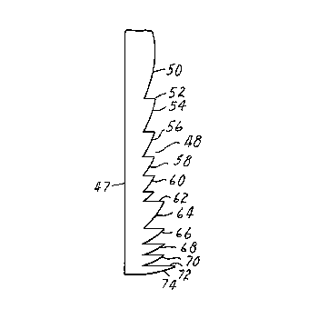
Figure 2, illustrates the lens according to the
present invention. The lens of Figure 2, includes a smooth
surface 47 and a structured surface 48. As shown in Figure 2,
smooth surface 47 is planar and the bases of the structures on
structured surface lie in a plane. Alternately, surface 47
could be curved or the structures on structured surface 48
60557-3950
CA 02022049 2000-03-14
7a
could be superposed on a curved surface having a finite radius
of curvature or both. In such a case, the lens could add
refractive power to the diffractive power.
2~2~p49
_g_
As shown in Figure 2, the diffractive zones are
formed as structures on surface 48. These structures
cause a relative phase shift between two rays of light
striking the lens immediately on opposite sides of an
optical step. This phase shift arises from the difference
between the indices of refraction of the lens material and
the surrounding medium. If a diffractive lens having
smooth surfaces is desired, the diffractive zones could be
formed by implanting selected regions of the lens with a
dopant that alters the index of refraction of the lens.
Alternatively, the zones could be formed on the interior
of a lens by covering surface 98 with a material with a
different index of refraction.
The structure of Figure 2, avoids the problem of
the small size of the outer zones by combining what would
have been two or more zones according to prior art into a
single zone. Thus in the lens of Figure 2, zones 50, 54,
56, 58, and 60 correspond to the first 5 zones of the lens,
of Figure 1. The optical step associated with each of
these zones, such as optical step 52, all have an optical
height equal to the design wavelength. Diffractive zone
62, however, corresponds to zones 6 and 7 of the lens of
Figure 1. Diffractive zone 62 is therefore the first
"superzone," a zone corresponding to more than one zone of
a Prior art lens. The step 64 associated with zone 62 has
an optical height equal to twice the design wavelength.
Similarly zones 66 and 68 would each have a width equal to
2 zones of a prior art lens and would have steps having an
optical height equal to 2 times the design wavelength.
Diffractive zone 70 is a superzone corresponding to 3
diffractive zones of a lens of the prior art. The step 72
associated with zone 70 has an optical height equal to 3
times the design wavelength. Similarly zone 74
corresponds to 3 zones of a prior art lens. In general, '
the invention may be characterized as a lens having
diffractive power where diffractive zones are terminated
by optical steps where one group of zones has optical
2022040
_g_
steps having optical steps with optical heights equal to
j~ and a second group of zones has optical steps having
optical heights equal to ka where ~ is the design
wavelength of the lens and j and k are unequal nonzero
integers. As described with respect to the lens of Figure
1, this requirement may be more precisely stated by saying
that the first group of steps have optical heights such
that they introduce relative phase shifts of 2jn at the .
back conjugate point between light rays of the design
wavelength emanating from a point source on the optical
axis at a distance equal to the front focal distance from
the lens and striking the Lens immediately on opposite
sides of a step while the second group has heights that
introduce relative phase shifts of 2kn at the back
conjugate point between light rays of the design
wavelength emanating from a point source on the optical
axis at a distance equal to the front focal distance from
the lens and striking the lens immediately on opposite
sides of a step, where j and k are unequal nonzero
integers.
Figure 2 shows a lens utilizing 5 zones similar
to the zones of the prior art, 3 zones corresponding to 2
zones of a prior art lens and 2 zones corresponding to 3
zones of a prior art lens. Those skilled in the art will
realize that these numbers are arbitrary. In practice,
the number of zones in each group will be determined by
the size of those zones and the manufacturing equipment
available. When the zones of any given group become too
small to accurately produce, a new group is started where
the zones of the new group correspond to a large number of
zones of a prior art lens. Furthermore, there is no
requirement that super zones cannot be associated with
more than three prior art zones. The maximum number must
be determined on a design-by-design basis. Normally each
group of zones will include a plurality of zones, although
it is entirely possible that one or more of the groups
would include only a single zone. Furthermore it is
2022049
-lo-
possible to skip one group, going, for example, from a
group of superzones where each zone corresponds to eight
prior art zones to one in which each superzone corresponds
to ten prior art zones.
Figure 3 shows a lens corresponding to the lens
of Figure 2, except that the diffractive zones utilize a
linear approximation to the curves of the zones of Figure
2.
A possible alternative approach to the invention
would be to make all of the zones in the lens superzones
of the size of the largest superzone required. A
disadvantage to such an approach is that deviations from
the desired hyperbolic contour in the zones closest to the
optical axis degrades lens performance by a greater degree
than such deviations in zones more remote from the optical
axis. This problem is magnified in a lens using the
linear contour of Figure 3 because the linear
approximation deviates from the hyperbolic contour more in
a superzone than in a single prior art zone. Thus, the
invention allows the use of superzones in the regions
where the performance degradation is minimal and standard
zones, or superzones corresponding to fewer standard
zones, in the regions where performance degradation would
otherwise occur.
Figure 4 is a front view of a circular lens
according to the invention.
Figure 5 is a front view of a diffractive lens
having linear rather than circular zones.
SWB/srd
SWBAPP9(13)