Note: Descriptions are shown in the official language in which they were submitted.
2 ZI ~
,' ~ ~' '' '
~"",';~;
, ' ~ ' , . ,:
. ': : ,',
",''
,`.~." ~
INSULATED INJECTION MOLDING NOZZLE
" . . ...
BACKGROUND OF THE INVENTION . ....... .... `
1 This invention relates generally to injection
molding, and more particularly to an injection molding -
nozzle having an integral electrical heating element
,...., :..
surrounded by layered ceramic insulation. `
Injection molding nozzles having integral spiral
. ,,
electrical heating elements are well known. For instance,
the applicant's U.S. patent number 4,238,671 which issued ~ ~;
December 9, 1980 shows a helical electrical heating ~
~: .... ~,
;~ element cast into a conductive material around a high
strength corrosion resistant inner core portion. More
. . . . . .
recently, the applicant's U.S. patent number 4,865,535
which issued September 12, 1989 shows a nozzle in which
;~ the heating element has a multiple thickness extending
into a tapered nose portion. As shown in both of these
~ 15 ~
: :
,
2 2~a22~2~ ~ ~
,~.
. ':
1 patents, it is also well known to provide insulation
between the heated nozzle and the surrounding cavity plate
by havins an insulative air space between them.
With the development of smaller sized injection ~ ~-
molding components and the increased demand for more
...~.. . ...
temperature critical materials, the relationship of
heating, cooling and insulation in injection molding
.,., ., .~, .., ~
systems has become even more critical to successful -
operation. This is particularly true for systems using -- -
temperature assisted or thermal gating. An example of ~ ~
,, :...
thermal gating using cooling is shown in U.S. patent ;
number 4,687,613 to Tsutsumi which issued August 18,
.
1987. Examples using heating are shown in the applicant's
U.S. patent number 4,911,636 which issued March 27, 1990 ;~ ~-
and U.S. patent number 4,922,082 to 8redt et al. which
issued May 1, 1990. The length of cycle time is also a
factor which is critical to the successful operation of ~
these systems. Thus, temperature time response as well as ;I~-
location of the heating and cooling relative to the gate
is very important. While these previous nozzles are
satisfactory for many applications, in addition to thermal
conductivity problems, some of them have the disadvantages
that they are relatively costly to make and the location ~-
of the heating or cooling elements adjacent the gate
structurally weakens them.
:- `
.
3 2~22~ 2~
SUMMARY OF THE INVENTION .
1 Accordingly, it is an object of the present
invention to at least partially overcome the disadvantages
of the prior art by providing an injection molding nozzle ~ .:
having an integral spiral heating element surrounded by
alternating layers of steel and insulating material.
To this end, in one of its aspects, the ~- .
invention provides an elongated injection molding nozzle ... ~
to be seated in a bore in a cooled cavity plate, the . . :
nozzle having a body with a forward end, a rear end and a
melt bore extending therethrough to convey melt from an .
inlet at the rear end to a gate leading to a cavity, the . :
nozzle having an electrically insulated heating element `:
with a spiral portion having coils which is integrally ::~
brazed to extend concentrically around at least a portion
of the melt bore, the improvement wherein the spiral ~ -
portion of the heating element is surrounded by a ~. -
plurality of layers of steel alternating with a plurality
of layers of insulating material, the layers of steel
including an outer layer and an inner layer which is
sprayed over an outer portion of the coils of the spiral
portion of the heating element, the layers of steel other
than the inner layer each being sprayed over an inner
adjacent one of the layers of insulating material, the
:~
-~ 4 2022I24
1 layers of insulating material each being sprayed over an ~ ~ ~
. ..; .,
inner adjacent one of the layers of steel.
F~rther objects and advantages of the invention `~
will appear from the following description, taken together
with the accompanying drawings.
BRIEF DESCRIPTION OF THE DRAWINGS
Figure 1 is a sectional view of a portion of an
injection molding system showing a nozzle according to a ; `~
preferred embodiment of the invention, and
Figure 2 is an enlarged sectional view showing
the same nozzle.
-, .
DETAILED DESCRIPTION OF THE DRAWINGS
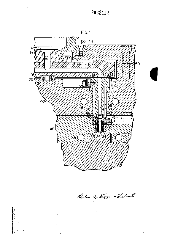
Reference is first made to Figure 1 which shows
. . .
a portion of a multi-cavity injection molding system. A
melt passage 10 extends from a common recessed inlet 12 in ;~
a manifold extension 14 to an elongated manifold 16 where ;~
it branches out to a number of outlets 18. As can be
seen, each branch 20 of the melt passage extends through a
rearward nozzle 22 and a forward nozzle 24 to a gate 26 ;-
leading to each cavity 28. The rearward nozzle 22 is a
conventional nozzle with an integral spiral electrical -~
heating element 30, and the forward nozzle 24 is a heated
.
~ 25 nozzle according to a preferred embodiment of the
'..~..~ ~ .;,
!~' ~ ' . ' : .
- 5 ~02`2;~2~ :
1 invention as described in greater detail below with
reference to Figure 2.
The elongated manifold 16 is heated by a heating
element 32 which is integrally brazed into it. The ~:
manifold 16 is held in place by a central locating ring 34 `~
and insulating pressure pads 36. The locating ring :
bridges an insulative air space 38 between the heated
manifold 16 and a cooled spacer plate 40. The pressure
pads 36 provide another insulative air space 42 between
10 the heated manifold 16 and a cooled clamp plate 44, The ;~
spacer plate 40~ clamp plate 44 and the cavity plate 46
are cooled by pumping cooling water through cooling `~
conduits 48. The clamp plate 44 and spacer plate 40 are :
secured in place by bolts 50 which extend into the cavity
15 plate 46. The manifold extension 14 is held in place by
screws 52 and a locating collar 54 which is secured to the
clamp plate 44 by screws 56. ;~
Each rearward nozzle 22 is seated in a well 58
in the spacer plate 40. It is located by an insulation
20 flange 60 seated on a circumferential shoulder 62 with a .
central melt bore 64 aligned with one of the melt passage - ~-
outlets 18 from the manifold 16. This also provides
another insulative air space 66 between the heated nozzle :
22 and the surrounding cooled spacer plate 40. In this
embodiment, the forward end 68 of the rearward nozzle 22
R.~ ~ `. . - ., , ~, . ..
6 2~Z23. ~
... ~, ....
1 has a gate insert 70 which is also seated in the rear end
72 of the forward nozzle 24.
Reference is now made to Figure 2 to describe in
.:: ~
detail the forward nozzle 24 according to a preferred :~
:::--:, ,-
embodiment of the invention which is received in a
matching bore 73 in the cavity plate 46. It has a steel
body 74 with a central cylindrical portion 76 extending
between a larger diameter collar portion 78 at the rear
end 72 and a larger diameter collar portion 80 at the -
forward end 82. The body 74 also has a melt bore 84 which :.
extend centrally therethrough from an inlet 86 at the rear -
end 72 which is aligned with the melt bore 64 of the :~ :
rearward nozzle 22 to the gate 26 at the forward end 82.
An electrical heating element 88 has a spiral portion 90
and a radial portion 92 which extends outwardly to a cold ;.
terminal 94 as described in the applicant's U.S. patent ~:
number 4,837,925 which issued June 13, 1989. The spiral '~
portion 90 is cylindrical shaped with the coils 96 wound-~:~
~ ,.
adjacent each other around the central cylindrical portion
76 of the body 74. The nozzle 24 also has a thermocouple
(not shown) to measure the operating temperature. In this
embodiment it is seated in a hole (not shown) which is
drilled radially inward in the body 74 adjacent the cold -.
terminal to nearly reach the spiral portion 90 of the
heating element 88. In other embodiments, the ~-
~ ''' ~'''~`''
: ' ~
: ~,
:
7 2 ~
1 thermocouple may be located further forward to be closer
to the area of the gate 26. ~-
The coils 96 of the heating element 88 are first -~
covered by a thin inner layer 98 of stainless steel which ` --
is plasma sprayed over them. The inner layer 98 of
stainless steel is then covered by a layer 100 of ceramic -~
insulating material such as alumina oxide which is plasma
sprayed over it. As seen in Figure 2, this is followed by i~
,~
several layers of stainless steel 102 and ceramic
insulating material 104 which are alternately plasma
sprayed over each other. In this embodiment, the layers
of stainless steel 102 are approximately 0.002 inches
thick and the layers of ceramic insulating material 104
are approximately 0.010 inches thick, although other
suitable thicknesses can be used. It has been found that
making the layers of ceramic insulating material 104
thicker than 0.020 inches when alumina oxide is used
results in unacceptable cracking. This is avoided by
using alternating layers of stainless steel and alumina
oxide. The outer layer 106 of ceramic insulating material ~ ~-
is covered by a thick layer 108 of stainless steel which
is plasma sprayed over it. In this embodiment, the thick
outer layer 108 of stainless steel is approximately 0.050
inches thick, although other suitable thickness can be ` ~-
used. Finally, the thick outer layer 108 has a plasma ~
2 0 2 2-1 2 ~
1 sprayed nickel coating 110 which can be machined to ~ .
provide a finished cylindrical outer surface 112.
In this embodiment, the heating element 88 has a ~`
nickel-chrome resistance wire 114 extending centrally
S through a refractory powder electrical insulating material ~ -
such as magnesium oxide 116 inside a steel casing 118. .--~
The coils of the heating element 88 are integrally cast in
a nickel alloy 120 by a first brazing step in a vacuum
furnace. As described in the applicant's U.S. patent ~
number 4,911,636 referred to above, brazing in a vacuum
furnace will result in the nickel alloy flowing by
capilliary action into all of the spaces around the coils
96 inside the inner layer of stainless steel 98 and .
metallurgically bonding to the steel casing 118 of the
coils 96 and the central portion 76 of the body 74. This ~:
produces very efficient and uniform heat transfer from the
coils 96 to the central portion 76 of the body 74 around
the central melt bore 84. .-.
A hollow cylindrical collar or shoulder portion
122 is then mounted over a rear portion 124 of the coated .
outer layer of stainless steel 108 adjacent the rear ;~
collar portion 78. The shoulder portion 122 is then -:
: integrally brazed in place by a second brazing step of
applying a copper-nickel brazing paste and heating in a
vacuum furnace. The shoulder portion 122 is made with a
~,'~ "'``~''
: '.~'.;
f`-' 9 2a~2`~4
...... ~
1 groove (not shown) to receive the radial portion 92 of the
heating element 88 and both the rear collar portion 78 and
the shoulder portion 122 are shaped to receive the
electrical terminal 94 when they are joined together.
In use, after the injection molding system has
been assembled as shown in Figure 1, electrical power is
applied to the heating elements 30, 32 and 88 to heat the
manifold 16 and the rearward and forward nozzles 22,24 to ~-
a predetermined operating temperature. Hot pressurized
melt is then introduced into the melt passage 10 through
the recessed inlet 12 from a molding machine (not shown) ;
according to a predetermined cycle. The melt branches in ;~
the manifold 16 and flows through the melt bores 64 and 84
: ~:
of each rearward and forward nozzle 22,24 to the gate 26
and fills the cavity 28. After the cavities 28 are full,
injection pressure is held momentarily to pack and then
released. When temperature assisted or thermal gating is ~
used, the electrical power to the heating element 88 is ~-
controlled so that no heat is provided for a short period
of time before and when the mold is opened which freezes
the gate 26. After a short cooling period, the mold is -~
:
opened to eject the container. Shortly after the mold is
opened, electrical power is reapplied to the heating
element 88 to start melting the cold plug so the gate
- 25 reopens when injection pressure is reapplied after the ~
: :
: - .
. ~.
.~
~2 2 1 2 ~
. . ~
1 mold is closed following ejection. This precise cycle is ~ -
repeated continuously with a frequency dependent on the
size and shape of the cavity and the type of material
~: .
being molded.
While the description of the insulted injection
molding nozzle accoeding to the invention has been given
with respect to a particular embodiment, it is not to be
construed in a limiting sense. Variations and
modifications will occur to those skilled in the art. In ;
lOparticular, it is apparent that the composition, number
and thickness of the layers 102,104 can be different for
. . -
different applications. Reference is made to the attached
claims for a definition of the invention.
,. :
," ' ~ ,''''.
." . ~.....
"~"
. ~
'' ~
. ~
.... .
`'' ' -'- .
' - -~ ~' . ', ""
~ . . :. .
':- . '' ' '
: ::: ...-: ::