Note: Descriptions are shown in the official language in which they were submitted.
2022293
SUMMARY OF INVENTION
Field of the Invention
- The present invention relates to an improved
method and system for remotely switching, regulating and
monitoring electrically operated devices by the use of
signals generated by a telephone or modem.
Description of Prior Art
In my earlier U.S. Patent No. 4,845,773 issued
July 4, 1989, I described a method and a system for
remotely switching an electrically operated device, such
as electrical baseboard heaters, by the use of signals
generated by a telephone. In that particular system, I
controlled remote switches by detecting a specific code
of sound signals generated by the telephone. It was
necessary to locate the switching system in close
proximity to a telephone whereby to detect the rlnging
sound whereby the switching system could be actuated.
With that particular system, I was more concerned with
the control of various electrical devices such as heat
pumps, motors, electric elements, contactors, etc.
However, there is a need to provide an improved system in
which it is not necessary to detect audible sound signals
and which has an infinite number of applications and
which is also programmable by the use of DTMF telephone
signals or modem signals.
SUMMARY OF INVENTION
Accordingly, the improved system of the present
invention is comprised of a common telephone input
consisting of two wires which are to be connected to a
standard telephone telecommunication network. A 12-volt
or 24-volt power supply and a battery back-up provide the
~ ? 2022293
power to the system with inputs and outputs for three
sub-systems. The first is an audio sub-system and
consists of microphones which allows the system to listen
to its environment. The outputs of this sub-system are
loudspeakers which permit the user to communicate with
the room on the other end of the line. This is similar
to a "hands free" telephone receiver. The second
sub-system is an t'ON/OFF" switching sub-system whose
input is the feedback line from the extexnal switching
element (sensor), and the ou.puts are dry contacts used
to switch electrically operated devices on or off
remotely by telephone. The third sub-system also
consists of inputs and outputs and wherein the inputs
represent analog variables (for example a pressure
measurement), and the output is a command signal (for
example to a motor ox actuator), which incrementally
changes the analog reference which is measured by the
input.
The device allows the remote access to the
three sub-systems through the use of a telephone or a
computer and modem. For example, if the user wishes to
speak to, or simply audit the activities in a conference
room, auditorium, classroom, etc., he/she simply
communicates with the system, accesses the audio
sub-system and commands either the speak/listen or simply
the listen mode of that system.
For the "ON/OFF" switching sub-system, the user
employs a standard DTMF telephone keypad to switch on or
off, or simply confirm the status of an externally
switched electrically operated device.
2~222~3
,
For the third sub-system, the user remotely
gains access to the system, again by telephone, and may
control and/or monitox the status of an analog variable.
A digitally synthesized voice will verbally convey the
status of the variable. The user may also vary the
predetermined setting of the reference for this variable
by commanding an incremental change to it. The user will
wait for and receive verbal feedback, via the digitally
synthesized voice, of the status of the changing
variable. This communication may also be performed by
computer if the user implements the "Computer Communica-
tion" via a modem.
Therefore, this is a bidirectional system where
the user may listen to a digitally synthesized message,
or audit the conversation in a room, or may remotely
switch on or off, or simply change the setting of an
analog variable, all commanded simply with a DTMF
telephone keypad.
This is a bidirectional system on the
"incoming call" level. The system also has the capacity,
via the "auto-dialer", to call and convey messages,
however, the system is unidirectional in this mode as it
is unable to receive commands. As an example of this
mode, the "ON/OFF" switching sub-system can sense a
malfunction in an electrically operated device, for
example, caused by an open or closed pressure switch
triggered by an abnormally high pressure buildup or loss.
There is an interruption requested in the interior of the
device which will then send an auto-dialing code in the
, ~-:
system, which proceeds to dial one or more preprogrammed
telephone numbers. A synthesized voice will communicate
-- 3
~ 202229~
the breakdown to the person who answers the telephone call.
This "auto-dialer" function may also be executed through a
modem. The system dials the modem telephone number and sends
the computer codes which identify the defective zone.
We can thereby conclude that this is a simple
"STAND ALONE" system, which is not as complex as the current
energy management systems used in large buildings or
industrial security systems. The system of this invention
easily connects with standard electrically operated devices
thereby rendering it universally functional with an infinite
number of possible applications, such as alimentary,
agricultural, manufacturing, plastic, industrial, process
control, government institutions and building management, to
name a few. It is pointed out that the three sub-systems are
not exclusively integrated in all system applications.
According to a broad aspect of the present
invention, there is provided a stand-alone switching system
for remotely controlling electrically operated devices or
monitoring locations by the use of DTMF code signals
generated by a telephone keypad. The system comprises a
telephone line input for connection to a telephone network.
An input interface circuit is connected to the input and has
an auto-dialer circuit. A communication circuit is connected
between the interface circuit and a microcontroller. The
microcontroller is connected to a switching sub-system for
switching the electrically operated devices and/or analog
control and monitoring sub-systems, all of which perform
predetermined functions implemented by the user through the
telephone keypad by using a programming or command access
algorithm through a series of option codes punched on the
keypad. The communication circuit operates in a DTMF or
-~- 2022293
modulated signals depending on the source of the input signal
codes. The input interface circuit has a digitally filtered
ring detector for discriminating between true telephone rings
and undesirable pulse signals. A switching device, when in a
first position, connects a telephone ring detector to the
telephone line to receive the true telephone rings and
connects them to the microcontroller. The microcontroller
causes the switching device to assume a second switch
position after the ring detector has réceived a predetermined
number of rings. Feedback signals are connected through the
second switch position to feed back information to the user.
A speech circuit is connected to an output of the second
position of the switching device. A modem circuit is
connected between the speech circuit and the microcontroller
for two-way communication through modulated signals or a DTMF
decoder circuit connected between the microcontroller and the
speech circuit for receiving and decoding DTMF function code
signals as well as frequency from the speech circuit to feed
the microcontroller to execute output or programming commands
or to monitor the status of the electrically operated
devices. The switching sub-system has a plurality of input
and output channels. The output channels are equipped with
switches to switch the electrically operated devices. The
input channels are connected to feedback signaling elements
to verify the operation and to monitor the electrically
operated devices which have been switched. The analog
control and monitoring sub-system has a plurality of input
and output channels. The input channels are monitoring
channels and receive analog signals from a remote industrial
device and converting same to a digital signal, said output
~ 2022293
channels feeding regulating signals to industrial actuator
~ devices to be controlled.
BRIEF DESCRIPTION OF DRAWINGS
A preferred embodiment of the present invention
will now be described with reference to the example thereof
as illustrated in the accompanying drawings in which:
<~
~ 202229~
FIGURE 1 is a basic block diagram showing the
main functions of the system of the present invention;
FIGURE 2 is a detailed block diagram showing
the global interconnections between the different
circuits used in the system of the present invention;
FIGURE 3 is a schematic diagram of the
telephone network interface with the system including the
circuit of the ring detector;
FIGURE 4 is an illustration of the calling
signals and pulses vs. the other undesirable signals to
be rejected;
FIGURE 5 is an algorithm showing the procedures
of the method to reject the undesirable signals
illustrated in FIGURE 4;
FIGURE 6 is an interconnecting block diagram of
the integrated circuits used to process the incoming and
outgoing telephone calls;
FIGURE 7 is a schematic diagram showing the
connections of the MODEM with the microcontroller and the
telephone interface;
FIGURE 8 is an interconnecting circuit diagram
of the voice synthesizer with the microcontroller, the
voice ROM and the telephone speech interface;
FIGURE 9 is a flow chart showing, via incoming
calls, the access to remotely controlling, supervising or
programming the system;
FIGURES lOA, lOB and 10C are illustrations
showing the locations and codes to program the options of
the system. The codes shown represent the factory
preprogrammed codes;
- ~- 2022293
FIGURE 10D is a table showing the switching
application attributes of the output channels when
programming the ON/OFF switching sub-system;
FIGURE 10E is a schematic ladder diagram
showing four different control circuit applications
illustrating the different switching output contact
activation methods and illustrating some examples of
supervision feedback connections for monitoring the
ON/OFF switching sub-system;
FIGURE 11 is a schematic and interconnecting
diagram of the audio sub-system showing the remote
controlled audio elements by telephone via a micro-
controller;
FIGURE 12 is a flow chart showing the remote
control and monitoring algorithm of the audio sub-system;
. FIGURE 13 is a flow chart showing the stay on
line and automatic hook-off algorithm when the system is
communicating via the telephone network;
FIGURE 14 is a flow chart showing the algorithm
to program the options of the system;
FIGURE 15 is a flow chart showing the remote
control and supervision of the ON/OFF switching
sub-system;
FIGURE 16 is a schematic diagram showing the
input channels of the supervision and the output visual
s-tatus monitors of the ON/OFF switching sub-system of the
invention;
FIGURE 17 is an illustration of the input
signals for the supervision of the ON/OFF switching
sub-system;
2022293
FIGURE 18 is a flow chart of the method used
for digitally filtering the AC supervision signals in the
ON/OFF switching sub-system;
FIGURE 19 is a schematic diagram showing the
output relay drivers controlled by the microcontroller
for the ON/OFF switching sub-system;
FIGURE 20 is a flow chart showing the remote
monitoring and temporary shifting of the reference window
for regulation of the analog control and monitoring
sub-systém;
FIGURE 21 is an interconnecting block diagram
showing the analog input interface between an external
linear transducer and the A/D converter for the analog
control and monitoring sub-system of the current
invention;
FIGURE 22-is an interconnecting block diagram
showing the output regulation interface between the
microcontroller and the external linear actuator for the
analog control and monitoring sub-system; and
FIGURE 23 is a flow chart showing the
auto-dialing and call process algorithm of the system.
DESCRIPTION OF PREFERRED EMBODIMENTS
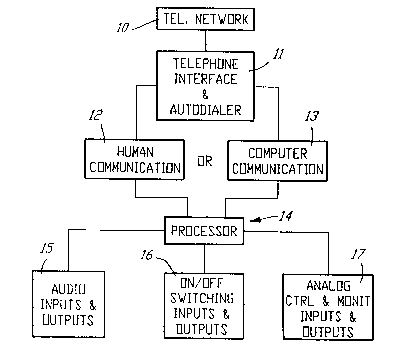
Referring now to Flgure 1, this block diagram
illustrates the general layout of the system including
the three sub-systems. The telephone network 10 is
connected via a simple telephone jack to the system
interface 11. This interface contains an "auto-dialer"
which would automatically dial a telephone number should
a functional defect occur. The telephone interface of
the "auto-dialer" is common for the three sub-systems.
Reference numeral 12 represents the user communication
- 8 -
;
i
2022293
with the device by use of a standard DTMF telephone
keypad. This communication is also possible via a
computer 13. The processor 14 is the control center of
the system. It integrates the algorithms and methods
implemented. The inputs and outputs are included in 15,
16 and 17, representing the three sub-systems, the
"audio", the "ON/OF switching" and the "analog control
and monitoring input/output" respectively.
In Figure 2, a more detailed block diagram for
the system is shown. The various lnterrelated circuits,
the heart of which is the microcontroller 22 is
illustrated in this Figure. Numeral 18 denotes the
protective filter which is incorporated on the printed
circuit board and is used to eliminate all transients and
surges over the telephone lines, thereby protecting the
system. Numeral 19 denotes a circuit which contains a
relay which can be in either the hook-on or hook-off
position. If all is normal, the relay will be in the
hook-off position. When the system answers the
telephone, the relay places itself in the hook-on
position. The relay is constantly monitored by the ring
detector 20 when in the hook-off position. This circuit
is used to analyze the pulses from the telephone rings
and will be further explained in Figure 3. The output 20
goes to the microcontroller and is analyzed algorith-
mically. The hook-on/hook-off relay 19, when in the
hook-on position, is connected to a clrcuit called the
"speech circuit". This circuit adapts the impedance of
the telephone line with the system, via the speech input,
all the sounds, signals, voices, etc., will pass through
this wire to the hook-on/hook-off relay contact. This
2022293
circult will be further explained in the discussion of
Figure 6. Note that the arrows in the illustrations
indicate inputs and outputs. For example, at numeral 23,
we note the "DTMF dialer", as it receives orders from the
microcontroller, lt will send DTMF signals in order to
dial the telephone numbers recorded for automatic message
sending to the outslde. Numeral 26 denotes the DTMF
decoder used to lnternally decode numerlcal functlon
keyed as well as the frequency from the speech 21, and
once decoded, wlll send them to the mlcrocontroller whlch
will execute eithex output commands or programmed
commands, or monitor the status of electrically operated
devices. This is done by the decoded DTMF, as given by
human input. Numeral 26' is an independent DTMF input
which ls used to glve commands to the microcontroller via
a local dual tone generator. The modem circuit 25
performs the same functions as the DTMF, but rather than,
as in the human case, the commands come from the speech
circuit, it is connected to another external modem which
modulates sounds in order to send digital signals to the
microcontroller via output 25'. Numeral 27 denotes the
call progress circuit which serves to monitor sounds from
the telephone llne in order to alert the microcont.roller
if there is no response from an automatically dialed
telephone number after a predetermined number of rings.
This circuit will send a code to the microcontroller by
communicating the status of the telephone line at that
given moment. The status refers to the sounds provided
by the telecommunication company in order to communicate
a "busy" signal, or other common sounds including a dead
(soundless) telephone line. The call progress circuit
-- 10 --
2û22293
will convey the status via a binary code to the
microcontroller, which will proceed to hook-off or
re-dial another number, etc., as will be later explained
in the call progress algorithm. The audio switching
circuit 28 is the audio sub-system 15 of Figure 1. It is
the sub-system which allows communication with microphone
or the loudspeakers in order to monitor or speak with a
room, moreover the sub-system which permits the
connection to the microphone, speaker, etc. Also present
are independent audio-in and audio-out inputs of
different impedance which serve to monitor the sounds
originating from audiovisual equipment, along with an
auxiliary input for a local preamplifier rather than a
speaker and microphone. The microcontroller is related
to a memory called the EEPROM 29 which is an electrically
erasable and programable read-only memory. The content
of this memory will be programmed by the user. We will
later explain the "custom" codes which the user may
program by telephone, such as the access code and the
master code which allow reprogramming of the device, the
telephone numbers which the device dials in its automatic
dialing mode, the number of rings after which the unit
will answer the Lelephone, etc. All this information,
along wlth the setup of the device, must be programmed in
the EEPROM and must be retained even during a power
failure. The external ROM 30 is a read-only memory used
to augment the internal memory of the microcontroller and
is devoted to the storage of the words, phrases and the
data used in the digitally synthesized voice which will
be monitored and controlled by the speech synthesizer.
Thus, the microcontroller selects the combinatlon of
20~22g3
words which must be used at a given time and sends this
to the speech synthesizer which then sends it to the
speech circuit so that the listener at the other end of
the phone line may hear the message. Therefore, the
words, phrases and various codes are all stored in the
form of binary codes in the "external voice ROM".
With ~eference to 31, 31', 32, 32', 35, 36, 35'
and 36', all these numerals collectively belong to the
"ON/OFF" switching sub-system 16 of Figure 1. In this
description, we are discussing only two input and output
channels, however the dash-line between 31' and 32
represents "n" systems with "n" possible input and output
channels. The output circuits 32 and 32' are identical.
They consist of dry contacts which may be programmed to
be normally open, normally closed, momentary action or
continuous action. These contacts serve to switch an
external electrically operated device, such as a motor
contactor, a heating element, lamp or lighting system,
etc. The inputs 31 and 31' are used to verify that the
command sent by the output was properly executed. For
example, the switching on of a motor by the output 32
drives a belt which in turn powers a compressor thereby
increasing the pressure in a tank. The tank contains a
pressure switch which will trip at a given pressure -
this switch will also provide a feedback input 31 and
will determine if the pressure is truly built up in the
tank. Therefore, this input serves to supervise the
output 32. We will later see that this feedback not only
serves to monitor the output, but also serves, in the
case of a malfunction, to send a signal to the
2~22293
microcontroller which will proceed to shut off the load
32. The m crocontroller will then access the auto dialer
and will communicate the problem to the user.
The visual indicator No. 1 t35) is a light
emitting diode which lights up if switch 31 is opera-
tional. This is to say, if output No. 1 is active Vl
lights up, similar to 35' which is for V2, but for output
No. 2.
With reference to 11 (36), this is a local
momentary action push button which is used to switch on
output No. 1 if pushed once, and to switch it off if
pushed a second time. In other words, Ll and L2 are
local commands used to activate or deactivate the outputs
without use of the telephone. Note that if the unit is
in contact with exterio~ telephone communication, the
operation of these inputs is inhibited. Visual indicator
VO ref (33) is the visual indicator connected to the
telephone network, for example a light, which will be lit
if the device is connected to the telephone network. If
the device is not connected to the network, then this
light will remain switched off. This is triggered vla
the switching element, which is a common switch LO (34)
which is in series with two wires that provide the
telephone connections to the input filter circuit 18.
Visual indicator VO (33) is not only a visual indicator
of connection, but as the telephone rings, it switches on
and lights up in unison with the rings of the telephone
allowing one to visualize that someone is contacting the
device. This same visual indicator VO (33) has a third
function which is the visual confirmation of the 7eroing
of the master code and access code, described later.
- 13 -
,i
20222~
This is used in the case of loss of the access code or
master code, which are normally programmed by telephone.
Due to their loss, either through attrition or forgetful-
ness, then this must be manually reset by dismantling the
device and shorting out two pins on the printed circuit
board. At this point, the system will reset the master
code to 0000000 and the access code to 1111. Visual
indicator VO (33) will blink rapidly in order to indicate
the re-setting of the hardware.
With respect to the analog control and
monitoxing sub-system 17 of Figure 1, it consists of
blocks 39, 39', 40, 40', 41, 42, 41' and 42'. The input
for circuit lA (for analog) will later be described in
Figure 22. It is also shown to consist of input and
output channels, but the dash-line between 39' and 40
indicates an infinite number of analog circuits. For the
time being, we will represent them as only two channels;
two inputs and two outputs. Input channel 39 receives
the standard analog signal from a remote source such as
an industrial process where we often find transducers
which give 4 to 20 mA signals, or 4 mA on the bottom
scale and 20mA on the top scale. This signal will be
interfaced to the microcontroller via an A/D converter.
The output 40 is capable of incrementally increasing or
decreasing the output signal which serves to regulate the
value of the actua.or. This actuator may be a motor, a
valve, or a servomechanism, etc.
Also, note that the microcontroller will
maintain the output at a given value or within a specific
range. The visual indicator lA (41) may be a liquid
crystal display which will display the value of the
- 14 -
-.- .- cr,~:
':' .'.
~ ~ 202229~
monitored analog variable. LlA may be employed as a
local switch increasing or decreasing the controlled
analog variable, whose output 40 is to be regulated.
Circuits 41' and 42' operate in a similar fashion. Note
that the microcontroller 22 also incorporates a "time
clock" function which is used in the "input/output
switching" sub-system giving it the capability of
preprogrammed switching (on and off at predetermined
times), complementing the telephone dispatched command.
The features of this timer, such as its ability to skip
Saturdays and Sundays, will be discussed later. The time
clock may be disengaged by programming of the device, and
then activated by telephone communication. The
microcontroller 22 manages all the operations of the
system, such as switching, communications, automatic
dialing, DTMF decoding, call progress analysis. It even
manages the mannex in which the speech synthesizer sends
its messages. The microcontroller is in fact the heart
of the system - and all the methods employed comprise the
control software of the microcontroller.
Block 43 represents the power supply and backup
battery charger.
Figure 3 illustrates thè telephone input filter
18 of Figure 2 ! the switch used to relay the telephone
network to the device, the hook-on/hook-off relay 48 to
the opto-coupler used to detect the rings thereby sending
this information to the microcontroller. Numeral 44
represents the tip and ring connection. Resistor 45 is
used as a protective fusible resistor while varistoxs 46
are used as voltage attenuators in the case of a power
suxge, by producing a voltage drop across 45, and in the
- 15 -
2022293
case of an extremely high transient voltage, actually
melt the resistor 45, thereby making it act as a fuse.
Therefore, this prevents power surges from passing
through the electronic circuitry. Switch 47 is similar
to switch 34 described in ~igure 2 and is used to switch
on and off the system's telephone line, while at thé same
time, the two poles serve to inform the microcontroller
of its "ON" and "OFF" position. The double pole, double
throw relay "DPDT" 48 in its rest position connects the
telephone line to the resistor-capaci~or network 49, 50,
51 52 which composes the input to the ring detector.
Resistor 49 serves to limit the current through the two
diodes 51 and 52. Capacitor 50 blocks the direct current
of the telephone signal while letting the 20 Hz
alternating current component pass through. Diode 51 is
used to remove the negative AC half-wave, while the light
emitting diode 52 illuminates with the presence of a 20
Hz frequency. This signal is then transmitted to the
opto-coupled transistor 53 which is then relayed to the
input port of microcontroller 54. This microcontroller
will proceed to analyze, uslng a procedure which will
later be described, the waves sent through the telephone
lines when the telephone rings When the microcontroller
counts a given number of rings, it will ask the device to
"hook-on". Transistor 55 will receive this signal from
the microcontroller to energize the coil of relay 48,
thereby switching the relay contacts to the hook-on
position. In this position, the ring detector circuit is
disconnected from the microcontroller while circuits 56,
57 and 58 will be connected to the speech circuit. The
speech circuit has an impedance in Ohms required by
- 16 -
:
- 2022293
communication companies, therefore, the line will be
loaded as per this regulated impedance. Diode bridge 57
is present in order to prevent the reverse polarity of
the tip and ring. Zener diode 58 is used to augment the
protection already provided by 45 and 46 in case the
voltage exceeds 40 or 50 volts. It will provide
protection from sudden transient surges (voltage spikes).
Capacitor 56 eliminates radio frequencies and filters
high frequency noises.
The transistor 59 and light emitting diode 60
a~e used as visual indicators and are illustrated in
Figure 2 by block 33. This light emitting diode will
turn on and off as the telephone rings, and will also go
off if switch 47 is in the off position, as shown. If
this switc~ is in the ON position, the telephone network
is connected to the device and the light emitting diode
will turn on. This same diode, as previously
described, will blink rapidly if the user resets the
access and master codes in the circuit.
The square waves 62 of a telephone ring are
illustrated in Flgure 4. These are seen at the output of
the opto-coupled transistor 53 when the telephone rings.
The envelope of these waves, representing the total time
for a calling pulse and silencej is illustrated in 61.
~ lternately, some telephone companies and
office telephone system manufacturers (for internal
calls) employ a double ring calling pulse 63.
The 20-cycle sinusoidal ringing signal 64 is
similar to the one "seen" by the opto-coupled transistor.
Due to the differences in the calling pulses generated by
different telephone system manufacturers and between one
20222~3
country and another, the microcontroller has been
equipped with a method of analysis for the calling
pulses. There is a switch ton either the hardware or
software) which is always in the off position. However,
when the device is installed by the user, this switch is
placed in the on position, thereby placing the device in
the learn mode. The user will then call from another
telephone and let it ring five or six times. The
~icrocontroller will study ~he particular calling pulse.
The user then disconnects the device placing the switch
in the off position. The system will have programmed the
particular calling pulse pattern within the EEPROM. The
device will then compare calling patterns from incoming
calls to these standards.
The pattern generated by a rotary dial
telephone connected on the same line is shown in 65.
When we dial a number on such a telephone, these may be
transmitted to the microcontroller which must discrimi-
nate and eliminate sùch pulses since they represent
nothing. The algorithm which analyzes and rejects these
pulses will later be described. The square waves 66
represent hook-on/hook-off "glitches". These glitch
patterns are sensed by the microcontroller via the
opto-coupled transistor. If they do not conform to the
pattern of the telephone rings, they will be eliminated.
The algorithm in Figure ~ represents the filtering method
of these undesired signals and is used to validate the
actual calling pulse.
Figure 6 illustrates the detailed speech
circuit 21 of Figure 2 with its inputs, outputs and its
interconnections with other blocks. The audio signal
- 18 -
-
2Q22~g~
output is accessed at 71 and 68. These two wires are the
output of push/pull amplifier used to drive a speaker.
This signal, available between 68 and 70 is caused by
voices from external telephone sounds along with the
signals emanating from an internal microphone 70. The
output audio signal coupled with the input to the DTMF
decoder The sounds coming from a distant telephone will
be decoded. This audio signal is also coupled with the
call progress circuit which serves to analyze the sounds
~rom an automatic dialing to recognize a busy signal, an
unanswered call or a defective communication. This same
audio signal if connected with the modem circuit input
thereby permits the analysis of the modulated signals
coming from an exterior modem connected to the device
through telephone lines. The microphone input to the
speech circuit is shown at 70. This input, as described
later, is used to send to an external telephone the
sounds within the room where the device in installed.
The DTMF input 69 is used to send all the sounds other
than those picked up by a microphone, such as the touch
tone sounds generated by the device during an auto
dialing call and those sent to the telecommunications
company. This DTMF input is also used by the speech
circuit as an input for the voice generated by the speech
synthesizer or by the internal modem The output signal
of this modem, shown in Figure 7, is sent to a remote
modem. Mute control 72 is a sound inhibitor towards the
output 71 and 68. While the auto dialer dials a
telephone number by pulse or touch tone, the mute control
attenuates the audio output so that these sounds are not
processed by the internal DTMF decoder. These tones are
- 19 -
:.;
202~93
not meant for the device but for the telephone company
which will link the device to an external telephone. The
microcontroller 22 will trigger the automatic dialing by
sending the information to the DTMF dialer via point 73
during an emergency interruption. This information, or
numbers, are stored in the memory of the EEPROM 29. If
the telephone company or this device fail to understand
the DTMF codes, it would be possible, via the micro-
controller, to auto-dial using the pulse mode rather than
the DTMF dialer 37, see Figure 2. The dialing of the
telephone numbers will occur with the rapid opening and
closing (10 pulses per second) of the hook-on/hook-off
relay. In the programming of the initial system
configuration, the option for pulse or DTMF dialer is
provided for, as will be discussed later. The call
progress circuit receives audio sounds in the input of 68
and contains a binary output 76 which is made up of three
bits. The eight possible combinations of these three
bits will tell the microcontroller the status of the
telephone line. For example, 000 may indicate that the
line is functional, 001 may indicate an occupied
telephone connection, etc. The valid data output 77 is
used to inform the microcontroller that the data input 76
is vaIid and may be accepted. Connections 75 are used as
control functions between the call progress circuit and
the microcontroller. The DTMF decoder 74 is used to
decode the tones and frequencies which emanate from the
speech circuit by line 68. These frequencies, generated
by the external telephone keypad, are decoded and the
results are transmitted to the four-bit data bus 78 which
gives a possible sixteen combinations-for the numbers on
- 20 -
`::
-- 2022293
- the keypad. The valid data 79 is similar to the function
- of 77. The DTMF input 80 is an auxiliary input. This
- input permits the inputting of local commands or to
. ,
' locally program the microcontroller with a local DTMF
generator without the use of a remote telephone.
~ - Figure 7 represents the modem circuit. Input
,. ~,
~ 81 represents the analog input to the modem and is
'; ~ connected to the audio output of the telephone speech
circuit of Figure 6. The modem transmit output 82 passes
through the telephone speech circuit before being sent to
- the outside, while 84 represents serial data sent to the
~~ microcontroller once demodulated by the modem circuit.
, : .
The serial data in 83 comes fxom the microcontroller and
are modulated before transmission to an outside modem.
"''
- The controls 85 are used to connect the modem circuit
with the microcontroller for data manipulation.
- Referring to Figure 8, the speech synthesi2ex
86 is an integrated circuit used to synthesize words and
- I phrases according to the serial data 90 coming fxom the
: - microcontroller. This data is stoxed in the voice ROM
, .
87, chosen by address 89 and sent to the microcontroller
to be subsequently transmitted to a speech synthesizer
,. . .
- 90. The vocal signal is transmitted through filter 92
before being finally sent to the telephone speech circuit
-- in order to produce the messages communicated to the user
on an external telephone. Control signals 91 are
.: , ,
~- - bidirectional linking the voice synthesizer 86 with the
~- microcontroller for the data manipulation 90.
~- Figure 9 demonstrates the programming or
command access algorithm. After detecting a given numbex
of telephone rings, the device connects itself to the
, .~
- 21 -
`:
: :: 2022~93
~ telephone line (hook-on position). Function 95 discerns
-- - whether it is a modem or human command on the other end.
-~ If it is a human command, the communication is made with
..: ,:
-` the DTMF mode, and in the case of a modem, then the
communication is accomplished with modulated signals.
The human on the other end of the telephone line may get
access by inputting a code. If this is an access code,
: -:
~ that is to say a valid four-digit code, the user may
,. . .
- access the sub-system selection by command 98. If it is
- ~ a master code, a seven-digit code, the user will directly
access the programming procedures 99. If the code is
- neither the access or master code, the system denies
. .
access and hangs up. Similarly for 97, the system
verifies if the code is an access code transmitted by
--~ modem, in which case, it will gain access to the commands
~- ~ via 98. If it is the master code, or any other code,
-~ - access is refused and the device hangs up. It is
- therefore not possible to program the system via point 99
.
- ~ using a modem. This may only be done with a DTMF
~- I communication. The programming procedures 99 will be
-` shown in another algorithm. The audio system procedures- .~
- ~- will also be discussed later, as will procedure 101 and
-- ~ 102.
~-~ ` The option codes shown in Figures 10A, 10B and
~; 10C are codes which are stored in the EEPROM memory and
- retained in the case of power failure. These codes are
- very important in that they are the starting point for
','. :,-
~ the operation o the system and sub-system. The codes
. .: .::
~ shown in this Figure are the default codes pre-progxammed
............... .
in the manufacturing of the system, and may be changed by
the user according to taste or application. Numeral 103
. , v,
- 22 -
~ " r. ~
"''` ~':
- -:
.~ ,
- 2022293
. -- -- , .
.~ .
denotes the personal access code. This is a four-digit
: code which may go up to 9999. As described in the
-: :
preceding Figure, this code allows access to the command
mode only, and not the programming mode of the option
~ codes of the system. Numeral 104 denotes the seven-digit
-~ "high level security programming master code". This code
~ .
gives us access to re-progam any of the codes shown in
~ ~igures 10A, 10B and 10C. The first four digits of this
.-,~: , .
- code cannot be the same as the first digits making up the
` personal access code 103. These two codes 103 and 104
-~ may be reset to their default value with the hardware, in
: ,:
case they are forgotten, by shorting two pins on the
printed circuit board. Other codes will remain
unchanged.
The "device identification transmission code"
105 is employed in identifying a malfunction as monitored
by the system. This code is used to communicate, when
the auto dialer calls the user, which of the monitoxed
devices tfrom 0 to 999 units) is malfunctioning. The
number of rings after which the device will pick up the
telephone line is given by 106. This number may be from
0 to 9. If the device is programmed to 0 rings, the
system will respond but to a unique 1nput condition; two
rings, hang up, call the device a second time at which
time it will answer after the first ring on the second
call. It is programmed in such a way so as to permit two
devices to be connected to the same telephone line. This
, .
would permit the user to program the first device to S
- ~
- rings, for example, and the second device to 0 rings.
---` The first will respond if we let the phone ring S times,
-
while the second device will only respond if we let the
- 23 -
.
:
:- ~ 2022293
."
- phone ring twice, hang up and call again. They both
cannot answer the same call. Therefore, this permits
: ~
`~- economical use of the user's telephone network; a unique
;. telephone line for two devices. This feature also allows
:~: ".
the user to connect a telephone answering machine to the
-
same telephone line as the device. If the user wishes to
- communicate with the device, he lets the phone ring
:
- twice, hangs up and calls again; thereby circumventing
the answering machine if it is programmed to answer after
three or more rings.
',~ '
~ - Numeral 101 denotes the selection of the
:j: :
language used for the voice synthesizer. 0 is for
-~ ~ English l, 2, 3, ...... up to 9 different languages may be
.-
permitted, if necessary. Numeral 108 denotes thepulse/tone selector for the auto dialer; 0=pulse, l=tone.
If the installation location of the device does not
: :
i accept DTMF codes for the dialing of telephone numbers,
~. .
j~j then programming in pulse mode is imposed. For this
~: ,...
case, set 108 to 0. If DTMF is permitted, the set 108 to
l. It is pointed out that even if the telephone line
' ",~;' .
-; does not permit dual tone, the programming and commands
~ for the device may be made in dual tone since the device
-~. integrates an internal DTMF decoder. Numerals lO9 and
llO denote the two telephone numbers programmed for auto
- dialing. The first digit of this series o numbers
defines whether communication is to be made with a human
,~ . "
~;5 0 or an external modem l. These numbers are dialed
;- sequentially, as will be later described by the
` respective algorithm. If the call is local, then the
.i-
number dialed, for example 555-5555 will be connected,
- and the next four digits of the number will be ignored by
:
- 24 -
20222~~
the telephone company. However, if the first digit of
-- - the telephone number is a 1, then the number dialed is : .
- ~ long distance and may be followed by a regional or area
,, .
code, such as 1-514-555-5555. The default number
programmed in the system is a "no service" number.
All the option codes in Figure 10B, with the
exception of 118, are part of the "ON/OFF" switching
sub-system, with 111, 112 and 113 being closely related.
Option 112 is the "output contact arrangement" t with
0=normally open and l=normally closed. Considering that
our system simply has two channels, the right cell, which
is doubly framed, always represents the second channel.
In certain applications of this sub-system, it is
important that the output channel or the dry contact of
the output channel be normally open while for other
applications it would be normally closed. Before going
through the explanation for 113 and 111, it is important
. .: .
~ to define the meaning of both the output channel and the
,
control circuit. The term output channel with the dry
contact refers to latching relays, (see Figure 19)
reference Nos. 190, 193, 192, 191. The contact of each
relay is connected to two terminals, and this terminal
switches one external low voltage circuit supplied by the
user. The user programs each of the contacts to be
either normally open or normally closed. Additionally,
these contacts are programmed for continuous actlon or
momentary action or momentary pair action according to
each application (see Figures 10D and 10E). The term
control circuit as used here refers to one output circuit
connected to the sub-system and is used to control one
load only. If a load is to be controlled by means of a
- 25 -
2022293
. ` -
-, .
- momentary pair contact action, two output channels are
required to handle one control-circuit, for example, see
- Figure lOE. A control circuit serving a motor needs two
output channels of the sub-system, each programmed for
momentary pair contact action. In the case of a lighting
-~ system using low voltage control, the control circuit
~ will llkewise take two output channels of the sub-system,
-- each programmed for momentary pair contact action. A
~ control circuit switching a hot water heater on/off uses
-~ only one output channei programmed for continuous contact
action. A control circuit to set a security system "on"
and to reset it "off" uses always only one of the
.. .. .
channels programmed for momentary contact action. Choice
~ of contact action determines the number of available
" - control circuits. When all output channels are
- programmed for continuous or momentary or a combination,
the sub-system handles a maximum number of control
circuits, in this case, two control circuits. When
~ momentary pair action is selected, only one control
-~ circuit is available in our case, (see Mode Selection
:
Table-Figure lOD).
- Referring to Figure lOE, there is shown the
: :-
~ coil 257 of the contactor for motor starting, when
., ,
controlling a motor. Each of the two output channels 260and 261 must be programmed for momentary pair action.
The output contact 260 used for starting will be
programmed normally open. The contact 261 used for
stopping the motor will be programmed normally closed.
The start push-button 255 is located in the control panel
of the motor and 256 is also the stop push-button located
also in the motor control panel. An auxiliary contact
- 26 -
-:- 2022233
259 of the coil 257 is used to maintain the start action.
The thermal overload contact 258 protects the motor. The
supervision input terminal block 264 corresponds to
channel No. 1 of the system. The normally open pressure
switch 263 will close when the motor builds up a
pressure. Contact 262 is the auxiliary contact of the
coil 257. A few seconds after starting of the motor,
contact 263 will close and contact 262 also will close
and the supervision terminal block 264 of channel one
will receive the feedback signal. In a low voltage
control of a lighting system, both output channels on and
off, contacts 250 and 251 are programmed normally open
and provide momentary pair contact action. The momentary
pulse lasts half a second. If a pair of output channels
is programmed for momentary pair contact action, the
first push-button 181 of Figure 16 and push-button 36 of
Figure 2, will switch the load on. The second
push-button will switch it off.
Referring to Figure lOE, there is shown the
coil 266 of the contactor for controlling a heating
system. The coil is switched on and off by a programmed
continuous action of contact 267. The thermostat
normally closed contact 268 will cycle on and off to keep
the temperature of the heated water constant. The
thermostat 269 which is normally open will give the
feedback to the supervision input 270. In the security
system 271, the momentary key switch 272 is used to
trigger the security system and also to reset the
security system if it is turned again. The momentary
action contact 273 of one output channel will trigger or
reset the security system by telephone. The internally
-2~-
2022293
continuous action contact 274 in the security system will
give the feedback to the supervision input 275 of the
sub-system to be monltored as set or reset, or as they
say in security slang, as in DAY position o.r NIGHT
position.
In the application mode option 111 of Figu.re
lOB, the digit which we may place in the right cell may
not be greater than 4 since the maximum for a double cell
system of two channels is 4 modes, as shown in Figure
lOD. In choosing the first mode in Figure lOD, the
device will be programmed for continuous action on
channel number 1 and continuous action on channel number
2. In the "auto-off" function 113, it must be noted that
if the digit, in the case of the second channel, is
followed by an apostrophe, depending on the application
mode chosen in 111, the data entered in this second cell
will be refused, if the control circuit of the selected
mode monopolizes two output channels.
The auto-off and emergency off 113 are features
of the system which the user has the option to program
enable or leave unused. It is used in an application
involving limit pressures or temperature, pumps, or
motors or similar loads programming the auto-off option
and the emergency-off option causes the system to
instantaneously and permanently disconnect the load if a
monitoring circuit detects stoppage of a load which
should be operating according to the position of the
corresponding output channel. If when monitoring,
feedback of supervision is interrupted, the system will
cause an automatic dialing of the telephone numbers as
shown in 109 and 110. The difference between the
: : i
~:
2022233
,. . .
emergency-off and the auto-off is explained as follows.
If the auto-off mode is programmed, that is to say 1, the
~-~, ,,
user may remotely reconnect the load in question by
re-telephoning, even if it was previously disconnected.
If the malfunction persists, the system will shut it down
again. However, if the emergency-off is programmed, that
is to say, a 2 is placed in this cell, then it would be
impossible to turn on a load once an interruption is
caused by a malfunction. A local reset will reconnect
the load by pressing button 181 of Figure 16 five times.
If in 111 the chosen application comprises of one or two
momentary channels, as in mode 2 and mode 3 in Figure
~t: .
lOD, in 113 the program will refuse all the auto-off and
emergency-off for each momentary channel. The reason for
,,
this is as follows, as shown by 272 in Figure lOE, if 273
is used to trigger-on or trigger-off the alarm system,
the supervision 275 will serve to give the information by
telephone regarding the status of contact 274 and not to
deactivate contact 273 by sending a second pulse. In the
case of "mismatch", this pulse, rather than trigger-off
may trigger-on the system. For option 115, the
:
-~ "auto-dialing function", O=disable, l-enable the auto-
dialing, has little to do with the option chosen in 113.
If the auto-dialing is selected, it will be executed for
~ all disaccord or conflicts between the supervision and
; the state of the command.
Examples of disaccord or conflict exists
. . .
between the supervision monitoring input and the status
of the output channel, if the system responds to a
telephone command to connect load 1 and the load cannot
- be turned on. For example, the load may be a broken
.: ,'-
~ - 29 -
:
: `
.:
2~2293
.. ..
. .
- drive belt, defective heating elements, burned out
filament, etc. Monitoring input of channel 1 receives
feedback of 0 volts or if the system is functioning
normally, and aftex a few minutes or hours, something
- goes wrong with the supervision input, the system will
- provoke an interruption and wil auto-dial to send to the
~ ; user a malfunctioning message. We call this a disaccord
- or a conflict between the output status of the channel
and the input supervision monitoring status. Programming
~:-, .
- the option function 115 with 1 (see Figure 10B), will
enable the auto-dialing features and programming it with
- a 0 will disable the auto-dialing monitoring feature.
~ The code 114 represents a feedback waiting delay.
- Referring to Figure 10E, coil 266 controls a
.~ .
heater element in a water tank. when phoning the system
-~ to command contact number 267 to close, the temperature
of the water will not rise fast so thermostat 269 will
: :'
~ close maybe after ten minutes and during this time of ten
~::
~- minutes, we could have a signal of disaccord because the
supervision 270 will not be in accord with the action of
. . .
closing of contact 267. The delay needed to inhibit
temporarily this non-correct disaccord has to be set in
114 of Figure 10B option. The proper number to program
in this case is 7, because 7 gives a delay of 640 seconds
which is equivalent to ten minutes and forty seconds.
Please note that the setting numbers are not linear with
the delay seconds. 0 is used for one second, 1 is used
for ten second delay, 2 is used for twenty second delay
and 3 is used for doubling twenty seconds, that means
forty seconds. Number 4 is used for eighty seconds, 5
for 160 seconds, and so on. Option functions 116 and 117
, .
"~
- 30 -
-3- 2022293
are the time clock options. These two options are used
to turn on or turn off the output channels without
telephone communication. These are used as a timer
independently from the commands received by telephone.
In 111 an application where one control
circuit is selected with two momentary pairs of contacts,
in 117 if the user wishes to turn on the load, say at
7:20 a.m. to 5:30 p.m. for every day except Saturday and
Sunday. We therefore enter 07:20 for 7:20, i7:30 for
5:30 p.m. and the last digit is zero because we want the
system to stay OFF on Saturday and Sunday. The second
series of digits will not be accepted because we have
only, in this case, one control circuit because we
programmed 111 with a momentary pair of contacts as shown
in action mode No. 4 (Figure 10D).
Options 111 to 115 are in effect together with
option 117. Numeral 116 denotes the real time clock
setting when we set up the system and these settings are
necessary to synchronize option 117. The programming
option 118 is associated with the audio sub-system and
configurates the switches 142, 143, 144 and 145 of Figure
11, to enable two-way audio communication for channel 1
if programmed at 0. Switches 142 and switch 144 will
stay closed to enable the speaker and the microphone of
channel 1. By entering a 1, switch No. 142 will stay
open. Switch 144 will stay closed, only if the
microphone of channel 1 is enabled. In option 118, if we
enter a 2, this will disable only the microphone of
channel 1 which means that switch 144 will stay open and
switch 142 will stay closed. Entering a 3 in 118
20~2293
." .
, . ..
disables completely the audio features of channel 1. The
-~ ~ same is applicab]e for channel 2 which consists of switch- :-
~- Nos. 143 and 145.
:
- - In Figure 11, we show a complete audio system
: ~ -
~ - with the controls. The terminal 130 is the input audio
;~ of this circuit which comes from the telephone speech
circuit. The two wires 130 and 131 come from the
~ push/pull output amplifier from the telephone speech
- circuit to be connected to the telephone handset shown at
-; 132, and called also the speaker of the handset which is
-~ normally an open circuit because switch 134 is not pushed
on the handset. The microphone 133 of the telephone
,
-~ handset is-used to work with the speaker 132. When
switch 134 is not pushed, the signals generated by the
-; :
microphone 133 are shorted to ground. To speak and
listen with this telephone handset, the user should push
~ the switch 134. This telephone handset is auxiliary and
-- is installed close to the system to allow occasional
~- ~ communication with two persons, one close to the system
. :.
and the other person out of the premises using anothex
:
- telephone. Capacitor 135 allows AC coupling between the
signal generated by the telephone speech circuit and
-~ amplified by the amplifier 136 which has a push/pull
output to drive speaker LPl and LP2 137, and 137'.
-~ Microphones 138 and 138' could be installed in rooms and
-~ the signal generated by these microphones is amplified by' the amplifier 139. This amplified signal is AC coupled
- with capacitor 147 to finally be connected to the
- microphone input of the telephone speech circuit (see
Figure 6 - reference 70). To eliminate feedback between
the microphone and the speaker of the same channel, an
~-.. ..
- 32 -
~ 2022293
automatic gain control 140 with 141 serves to change the
gain of the amplifier 136 when somebody is speaking in
the microphone 138 or 13B'. As shown in Figure 10C, all
of these programming options are in the configuration of
the analog monitoring and control sub-system.
Referring to Figure 10C, options 119 and 120
are the type of read units and the name of the unit for
the speech synthesizer messages. The two first digits
are reserved for channel No. 1 and the next two digits
are for the channel No. 2. The number entered in the
programming option 119 allows the microcontroller (see
Figure 8) to retrieve from the voice ROM 87 the proper
message unit to be sent by the voice synthesizer to the
telephone network. Example, if the type of unit read by
the input transducer of channel 1 is the temperature, the
message sent by the voice synthesizer should be the word
"temperature". In the voice ROM 87, the listed type of
units are 45 if the type of unit used is not listed, the
user should program 00 for the word "reading". Example,
the message will be "the reading is" or "the temperature
is" or "the pressure is", etc...
Option 120 in Figure 10C is used to program the
good name of the unit needed. In the same way, the voice
ROM lists 45 names of units. Example: degrees Celsius,
degrees Fahrenheit, kilopascal, psi, etc. If option 120
is programmed by 00, the word will be "units" sent as a
pa~tial message by the voice synthesizer and an example
of a full message will be: "The reading is 23 uits" or
"The temperature is 25 degrees Celsius" or "The pressure
is 2.5 psi".
3~_ 2~22293
Referring to Figure 21, the external linear
transducer 220 translates an input physical variable to
an electrical standard signal, for instance, from 4 to 20
mA, and this signal of 4 to 20 mA is interfaced by 221
analog scaling interface to a signal of 0 to 5 volts DC
which is proportional to the input variable read by the
transducer. The internal A/D converter included in the
microcontroller 222 will allow to digitalize the actual
instant value of the read variable by the transducer with
a ten-bit output definition. Numeral 223 is the last
channel used.
It is pointed out that the present system is
not limited to a two-channel system.
In option 121 of Figure lOC, the programming
cells associated with channel No. 1 are composed of four
digits. The first digit specifies the minus sign and the
three others, the bottom scale magnitude setting. The
message sent according to the reading of the input
variable could be in a range of 999 sampllng points. In
the top scale magnitude setting 122, the fixst digit
designs the minus sign, if the minus sign exists, and we
should enter a 1 in the first digit. As shown in Figure
22, the external actuation element 228 could be a valve,
a motorized potentiometer, or any kind of actuator that
should be regulated. The output interface circuit 225
will generate signals, pulses, or other types of
variables which will keep the external actuation element
regulating the variable which is read by the external
linear transducer 220 of Figure 21. The analog
monitoring and control sub-system is also a regulator
sub-system; see Figure lOC.
, ~
:'
-
. ~ .
2~22293
;
Option 123 in Figure 10C is the center window
~ reference for regulation. Numeral 124 denotes the
- boundaries of the window in which the reference is in the
~`:
- ~ middle for tracking the regulation. The minimum delta of
~ i these boundaries could be set to 1/100 of the full scale
:::
which means a regulation of plus or minus 0.5% according
to the center window reference 123. The maximum delta
regulation boundaries is 99 which means 1/10 of the full
scale which gives a regulation of plus or minus 5%
according to 123.
Option 125 is the decimal scale divider and has
three values: 0, 1 and 2.0 divide by 1, 1 divide by 10
and 2 divide by 100, all the values being read according
to 121 to 123. For example, if we set 121 as being 000,
and 122 as being 100, that means 0100 if the decimal
scale divider is set to 2 for channel No. 1, and that
means that the value read has to be divided by 100. The
voice synthesizer 1 when the transducer will produce 20
milliamps which will be 1.00 instead of 100. If the
transducer gives 8 milliamps, the messaqe will be 0.5.
Programming option 126 allows interaction between the
analog control and the monitoring sub-system with the
ON/OFF switching sub-system and if the number entered in
the cell is 1, it allows this interrelation. This means
that if the variable stays out of the boundaries for moxe
than the delay setted in 127, the auto "OFF" or emergency
"OFF" option 113 will deactivate the channel related to
these variables by stopping a motor or switching off an
~ -:
- external element that affects these variables. This
interrelation is not a regulation option, but an extra
,-`.: ''
safety of the system used as an over-limit or cut-out.
- . .
- 35 -
2~22293
- Option 127 allows the user to program the
reading rate of the sampling in the analog monitoring and
control sub-system. Some variables do not change fast.
For instance, temperature could change very slowly. The
time constant of the variable should be taken into
conslderation by programming the proper reading and the
regulation rate. The variable reading rate could be set
from 1 second to 10 seconds; 1 second for the faster time
constant and 10 seconds for the slowest. This option
also is not exclusive. If we use two cells per channel,
reading and regulation rates could be set higher than 10
seconds. This rate is also the speech message rate,
which means that when the user is calling the system to
monitor the analog variable by synthesized voice
messages, the first message is complete and the next
sample messages are shortened. Example: the temperature
is 25.6 degrees (first message), 2S.7 degrees (second
message), 22.2 degrees (third message), etc.
Option 128 in the analog control and monitoring
system permits to command by telephone to shift up or
down temporarily the center of the window reference to
increase or decrease the tracking level of the regulation
(temporarily). Then we proceed to the programming
procedure algorithm 99 (see Figure 9).
Referring now to Figure 14, there is shown the
algorithm when calling from another telephone line.
After a predetermined number of rings, the system will
answer by giving a message from the device identification
transmission code. The user should enter the master
programming code. If this is correct, message 160 will
follow: "Please enter the option number you wish to
- 36
- 2~222~
program". At 161, the option number corresponding to one
of the programming options shown in Figures lOA, B or C
is entered by using the keypad of the touch tone
telephone. After the option number is entered, messase
162 wL11 send you a message that confirms the option
number you have entered. If correct, you should enter
the new option code, if not, you will try again. After
you entered your new option code, 164 will confirm by
message all the numbers you have entered to program the
new option code. If these numbers correspond to your
programming, you can hang up or you can program another
option, or the same option if necessary. As shown in
Figure 9, item 98 selects the command procedure of the
three sub-systems. If the number of channels is greater
than 2 for each sub-system, connection of supplement
channels could be modular and interconnected with the
main system via twisted pairs of wires. Each of these
modules has its proper microcontroller and the main
microcontroller of the system will manage the
interconnection of each sub-system and each module with
the system.
Now we will explain the command procedure audio
algorithm 100 with reference to Figure 12. This
procedure is designed to function with humans and by the
use of the DTMF codes to command the speakers or to
control the microphones. From an external telephone
line, the user telephones the system and after a
predetermined number of rings, the device answers by
giving the device identification transmission code. The
user should enter his personal access code. If this code
is correct, after selecting the number which gives him
i
2~22293
access to the audlo sub-system, an initial message 148'
will say: "Which audio channel would you like to
select?" The user via the commands of the DTMF codes
enters the audio channel number 1 or 2, 149. After
entering the channel number, a confirmation message will
say: "You have entered channel No. 1 - proceed or not?"
If correct, the device will permit the user (see 151) to
wait on the line, to speak or to listen to what is
happening in the room where the microphone of channel 1
is connected. The time which the user can stay on the
line is limited by regulations of the telecommunication
companies. So if the user does not touch a DTMF tone key
during this allowed tlme, the system wlll hang up
automatically, (see Figure 13). The stay-in-line
algorithm 154 explains the stay-on-line procedure. The
on-line timer is reset each time you enter a DTMF code
except the star (*). If the user does not touch any
command of the DTMF sounds, or frequencies, before the
on-line timer overflow, a time-off warning message 155
(that is a beep) advises the user that if he does not
touch any command of the DTMF codes, except the star (*),
the system will hang up automatically in a few seconds.
Touching the star (*) of the keypad obliges the system to
hang up automatically, even if the on-line timer is not-
overflowed.
As shown in Figure 12, there is provided a DTMF
interrupt test 152. If the user interrupts by DTMF
before the time-off warning message described in Figure
13 (155), the system will understand that the user wants
to scan another channel to listen or speak. If it is
yes, the confirmation message 153 will say to the user
- 38 -
;:
:
2022293
that he has asked for interruption to change the channel.
The next message 148' will be the initial message that
is: "Please enter the channel you want to monitor" and
so on. This terminates the audio command procedures.
Referring to Figure 13, there is shown the
stay-on-line algorithm 154. It is valid for any
procedure, programming procedure, audio command
procedure, on/off switching command procedure, or analog
control command procedures. As shown in Figure 9, a
command procedure 101 is provided for the on/off
switching of the sub-system. With further reference to
Figure 15, it can be seen that after a user has accessed
the system, via the personal access code, if selection is
the on/off switching command and supervision 165, the
initial message 166 will say to the user: "Enter the
control commands for a particular channel to be switched
off, switched on or a command to receive a message
confirm?.t1on of the actual status of the load". The one
- ,:
word command 167' is a series of few DTMF touch tone
entries. The first entry should be the channel number to
choose, the second entry is O for turning off, a 1 to
turn on, or a 9 to ask for a confirmation. If O or 9 was
chosen the system will execute the command, if a 1 is
chosen as a second digit, the system will wait for up to
3 other digits which have their own duration time in
minutes to keep the load on after the command entry.
When a 1 was chosen as a second digit, the last touch to
enter should be the number (#) on the telephone keypad,
for example, we want to turn on load No. 2 for 999
minutes, we should enter 21999 followed by the touch tone
number (#). In a second example, if we want to turn on
,~
, ~ .
- 39 -
. ~
.
2n22293
load No. 1 indefinitely, we should enter 11 followed by
the number on the keypad, and if we want to turn off load
No. 1, we should enter 10, the number ~#) is not needed
in this case. If we want to confirm the status of the
load No. 1 of channel 1, we should enter 19, and the
system will execute by sending a confirmation message in
this case, and the number (#) on the keypad is not
.
needed. If the second digit is a 1 and the number (#) on
the keypad is not entered, then the system will refuse to
~ -.
execute any command because it is not completed. If the
duration function 170 was entered, the system will
memorize the duration in 171. And, after executing the
~- command, the system will wait until the feedback delay of
.: .
the ~upervision is last, 172. Please see reference
numeral 114 in Figure lOB. Also, see Figure lOE,
-:- .:: .
reference numeral 266. Now suppose we ask a command that
is to switch on a heater for 99 minutes, the thermostat
269 for monitoring supervision will take up to six
:
minutes- to close because of the temperature thermal
constant of the water to be heated. When programming the
- unit for channel 1, (see 114 of Figure lOB), the proper
-~ number entered for this application is 25% greater than
the thermal constant of the hot water, to close the
~; - thermostat 269. Function 172 will eliminate the event of
a disaccord. The user who turned on the load in,question
::
` does not have to stay on the line to wait for the
feedback delay supervision. He can hang up and phone
later after the delay is last to ask for a confirmation
- I message to be sùre that the system responded with the
thermal constant delay. Even if the user does not call
.- :
- back~ if the system after the delay encountered is a
:::
- 40 -
2022293
-disaccord, the system itself will auto-dial after this
delay is last to say to the user that the feedback was
not correct after the delay of, the supervision. This is
why it is important to be accurate in setting of 114 when
programming the unit for these particular applications.
-- Referring to Figure 2, circuit blocks 31, 31',
32, 32', 35, 36, 35' and 36' denote the inputs and
outputs of this sub-system. Details of these blocks are
shown in Figure 16. The opto-coupler 179 permits the
interface of the exterior supervision circuit with the~
:
microcontroller 180. When a 1 is entered at input 1, it
is necessary for a voltage of a DC or AC current at a
specific frequency to be present for the microcontroller
to recognize that the supervision is present. This
signal which is applied to this input is a signal whereby
the decision of the microcontroller is binary on or off,
that is to say, whether there is supervision or not.
Therefore, it does not consist of an analog signal. Even
if the level of this signal may be 12 volts DC or 24
volts DC, or simply signals for 12 or 24 volts AC at an
industrial frequency, as illustrated by reference
numerals 184, 185 and 186 in Figure 17.
Referring again to Figure 10E, the terminal
blocks 254, 264, 270 and 275 are those found in Figure
16, input 1. For example, as terminal block 270 receives
supervision feedback, such as the closing of thermostat
269, a voltage of 24 volts AC will be present at the
block 270 signifying that the supervision is ON. If the
thermostat 269 is open, the potential at terminal block
270 i6 0 voIts, therefore, the supervision is OFF and
resistor 177 serves to limit the current flowing into
- 41 -
~222~3
diodes 178 and 179. Diode 179 is a light emitting diode
of an opto-coupler. Diode 178 is used to impede the
unwanted part of the sinusoidal input which may damage
the light emitting diode 179. The signals at input 177
may also be a DC as well as an AC of industrial
frequency. The processor, via the algorithm shown in
Figure 18 will accept the AC signals as a validation that
the supervision is ON. "TEST IF INPUT STATE OF A CHANNEL
STAYS ~OW FOR MORE THAN 100 MILLISECONDS, IF TRUE
CONSIDER THE SUPERVISION FEEDBACK OFF, IF NOT TRUE
CONSIDER IT ON". This statement permits the validation
of the AC signals at the input of the supervision has a
starting frequency of 10 Her~z up to frequencies higher
than 60 Hertz. If the AC signal at the input 177 is at
low voltage, less than 24 volts, the waves are saturated
at the exit of the op~o-coupled transistor 179 and
represented by square waves 186. The OFF periods of
these square waves should not last more than 100
milliseconds as in the worst case shown in 186 it is less
than 100 milliseconds as the completed period of the
square waves has a frequency of 10 Hertz and 100
milliseconds. The OFF period should be less than 100
milllseconds. If the signal at input 177 is 12 or 24
volts DC, the problem does not exist. This analysis
method for AC signals eliminates the need for filters
consisting of capacitors and diodes, thereby eliminating
the need of a mo e complex and populated circuit from a
material ~hardware) point of view. This method, as
illustrated in Figure 16 is achieved by a resistor, a
diode and an opto-coupler. The light emitting diode 183
is the visual indica~or described in Figure 2, reference
,,
- 42 - ~
202~293
35. Resistor 182 services to limit the current in this
diode as it illuminates. This diode, from a functional
viewpoint, indicates the accord or disaccord of the
output status of the contact for channel 1 and the
supervision status of the correspondent input. Push
button 181, also shown in Figure 2 as reference 36, is
used to locally activate or deactivate output number 1,
even if the operation could have been done by telephone.
In Figure 19, there is shown a latching relay
having a double coil 190 and 191 and contacts 193 and
192, respectively. When a pulse is sent to coil 190, the
two contacts 192 and 193 close. Whereas if a pulse is
sent to coil 191, these two contacts will open and remain
in one or another state even in the case of no power.
Contact 192 is the output contact of channel 1. The
other contact 193 is used to send information to the
microcontroller in order to know what position the output
contact is in. This internal supervision, via contact
193, is sampled at intervals of every tenth of a second
by the system in order to know if the contacts have
changed position for any reason, say a mechanical shock,
without the authorization or command of the micro-
controller. Varistor 196 is used to protect the circuit
from power surges caused by the opening of contact 192 in
the case that this is in series with a circuit of
external inductive coils. In addition to this, the
protection 196 increases the life of contact 192,
transistors 188 and 189 as well as 194 and 193, and
serves to drive the action of connecting and disconnect-
ing coil No. 1 or No. 2 from the latching relay.
- ~ r
2022~93
Referring now to Figure 20, if after accessing
the unit the user needs to proceed to the analog control
monitoring command sub-system, then after selecting that
sub-system, an initial message 199 will ask the user to
enter the proper commands to choose the channel to ask
for a monitoring confirmation to shift the window up one
delta or to shift it down one delta. Here reference
should also be made to Figure 10C which illustrates at
119 to 128' the programming configuration set-up option
programmed before the start-up of the system. The
algorithm illustrated in Figure 20 is similar to the
algorithm of the on/off switching supervision sub-system
of Figule 15. As in 167', the entry word to command for
a monitoring confirmation or to shift up and down are
also similar to the on/off switching supervision
commands. For example, the first diqit of the command
words should be the channel number, the second digit
should be 0, 1 or 9. No. 0 is to reset the window to the
original center window reference 123, if 9 is chosen as a
second digit in the command word, the system will confirm
by a synthesized voice the instantaneous value of the
analog input of the channel in question. If No. 1 is
chosen as a second digit, the system will shift down the
reference window for one delta. If 2 is chosen as the
second digit in the command word, the system will shift
up the reference window for one delta. Ylease note: in
case of entering 1 or 2 as the second digit, the user
must enter an ON duration delay ater which the system
will automatically reset the center window to the preset
value in the programming option 123. When 1 or 2 is used
.... .
as the second digit in the command word, the user should
2022293
terminate this command by pressing the (#) button on the
telephone keypad as we already described with reference
to 167'.
After the command is entered in the system, the
system will memorize the up duration (see 205) in minutes
and the system also at 206 will wait for an analog
feedback delay regulation rate as shown at 127. A
confirmation message will follow in circuit 207. If the
new value of the analog input is included in the new
shifting of the new reference window, the system will
wait at 209 for the next sampling followed by a new
confirmation message which has to be a value that is
included in the reference window. If there is disaccord
at 208, which means that the analog input signal did not
reach the new value of the reference window, the system
will reset the window according to the option setting at
123 and if programmed with a 1, see 126 at Figure lOC,
the system will also switch off the correspondent channel
in the on/off switching sub-system. A confirmation
message at 211 will follow. The user stays on the line
as the same algorithm 198 could shift the window up or
down a few times to increment the shifting not only by 1
but several times without having to hang up and to dial
again. Functions 212 to 218 have the same operation as
205 to 211. Function 201 refers to 167' and if the
second digit entered is a 9, then it refers to 203 and
204. The user stays on the line and listens fo~ many
minutes for the feedback confirmation of the instan-
taneous value of the analog input of the channel in
question. Each message will be repeated with the
sampling rate as programmed in 127 (see Figure lOC and
~ 45 ~
y~
202229~
Figure 13). In case the user stays on the line more than
the time allowed by the stay-on line algorithm, a
time-off waxning beep 155 will ask him to touch any touch
tone telephone number except the star (*) to reset the
on-line timer and to stay on the line waiting for the
next message. Please refer to Figure 23, wherein the
auto-dialing and system monitoring procedure 230 is
illustrated. This algorithm takes effect only if the
system is not in the communication mode, that is to say,
if a user is commanding the unit by telephone, this
algorithm is not in effect but will be in effect only
after the system is hung up. The interruption request
231 is the trigger to auto-dial. As shown in Figures lOB
and lOC, options 115, 118' and 128' are configuration
settings to allow the three sub-systems to enable or
disable the auto-dialing feature which could trigger the
auto-dialing procedure for the switch on and off
sub-system. As shown in Figure lOE, if elements 253, 262
263 or 269 or 274 opens, for any reason, and one command
is activated, this will trigger the auto-dialer. In the
analog control and monitoring sub-system of Figure 21, if
analog input 219 reading is out of the window 124 and 123
for more than the delay of the sampling rate 127, this
will cause a triggering of the auto-dialer for the audio
sub-system Function 118' enables microphones by
analyzing the sounds in the room and comparing them to a
pattern. The system can recognize the difference between
human voices and other noises or a specific noise
recognized which may trigger the auto-dialing system.
For example, an infrared motion detector, that is not
part of the present invention or other similar pick-up
- 46 -
.
2~2~293
elements that are used in security systems, could trigger
the auto-dialer by permitting the user in another place
to listen at what is happening in the place where the
microphones are installed.
As shown in Figure 23, the system 232 will set
. ,
to N the round counter, N being the number of times the
system has to dial as programmed in the configuration
option 110'. If the auto-dialing system can reach both
persons at the two phone numbers programmed in 109 and
110, the system will not telephone more than once. If
the auto-dialing system cannot reach one or both of the
phone numbers, it will try again for N times minus one
wi.hin an interval time in minutes as shown in Figure
10A, in 110". If after N calls the system will not reach
or cannot reach both of the two telephone numbers, the
light emitting diode 60 in Figure 3 will blink. The
blinking of the light emitting diode 60 will provide
proof that the system tried to call out of the premises
because of interruption and nobody was reached. Reset of
this light emitting diode could be done by activating the
push button 47 on and off, see Figure 3. Functions 239
to 245 illustrates the procedures to dial the first phone
number and the selection if the communication is to a
modem or a human (see 242, 243 and 244). The second part
of the algorithm for the second phone number is simila-r
to the first one. Function 247 relates to the
documentation of the round counter each time the system
dials again. The delay 237 illustrates the interval
between one call and another call. In the dialing loop,
the "OR" logic or test 233 will test if both telephone
numbers are reached. If yes, the system will hang up and
- 47 -
~ . 2022293
the light emitting diode 60 in Figure 3 will not blink.
The logic "N" test function 236 is the decrementation of
the ring counter and is equal to 0. The function 235 and
the test 236 will cause a hang-up and let the light
emitting diode 60 flash. This is only if both of the
telephone numbers could not be reached. If one is
reached, the light emitting diode will not blink.
Depending on the importance of the interruption request,
the user could set up the good number of calling time and
the interval between these calling times to be sure that
at least one of the two phone numbers can be reached and
all this according to the laws of the telecommunication
commission.
- 48--