Note: Descriptions are shown in the official language in which they were submitted.
2022355`
Case 6006
BJL:cmg
10-02-89
IMPROVED FEMALE CONNECTING MEMBER WITH
DISASSEMBLY FEATURE FOR ARTICULATED CONNECTION
Background of the Invention
The present invention relates generally to the repair
of articulated connections in railway vehicles and, more
particularly, to an improved female connecting member and
method to facilitate removal of a ring seat from the female
connecting member.
The use of articulated connections with male and female
connecting members joining adjacent ends of railway cars on
the bolster of a single truck to form a semi-permanent unit
is well known and is shown in the following United States
patents, among others: Tack et al, U.S. Pat. No. 3,721,482;
Altherr, U.S. Pat. No. 3,716,146; Radwill, U.S. Pat.
No. 4,336,758; and Altherr, U.S. Pat. No. 4,258,628.
Furthermore, the female connecting members of
articulated connections are known to include an annular
groove within which a spherical ring and ring seat are
received to, in turn, act as a mounting surface for the male
connecting member. The purpose of such spherical ring and
ring seats are to allow, in part, for vertical and
horizontal ~ngling movement as well as rotational movement
between the male and female connecting members when their
respective railway cars are travelling on grades, around
curves or rocking with respect to each other.
The use of such parts in an abutting relationship under
high loads requires the maintenance of close tolerances to
20223~5
prevent high impact forces which cause excessive wear and
possible fracture within the connection. During an extended
period of service, the ring and ring seat and their
respective opposing surfaces wear resulting in the lowering
of the male connecting member and the car body to which it
is secured. Consequently, a corresponding decrease in the
restrictive space allocated for side bearing clearance
occurs which is below the minimum height set by the American
Association of Railroads. One way to restore the male
connecting member to an acceptable height is to place a shim
within the annular groove underneath the ring seat. This is
done by disconnecting the male connecting member from within
the female connecting member and lifting the ring and ring
seat from within the annular groove; placing the shim within
the annular groove; reinserting the worn ring and ring seat
over top the shim; and reconnecting the male connecting
member within the female connecting member.
A problem that has occurred dùring this maintenance
procedure is that the ring seat often becomes lodged or
"frozen" within the annular groove making it extremely
difficult and sometimes impossible to lift out. If the ring
seat cannot be removed during repair, it is then necessary
to destroy the ring seat, typically accomplished by cutting
it into several pieces using a cutting torch, to effect its
removal. Such destruction of the ring seat requires the car
owner to prematurely purchase a new ring seat.
~0223S~
Accordingly, it is an object of the present disclosure to
provide an improved female connecting member with means for
applying an upward force to the undersurface of a ring seat.
A further object is to provide a method for ejecting a
ring seat from a female connecting member.
It is proposed to overcome the difficulties encountered
heretofore. To this end, it has been discovered that providing
the female connecting member with one or more access
passageways extending from the exterior surface of its front
wall to the annular groove will allow for applying an upward
force to the undersurface of the ring seat to eject the ring
seat from the annular groove.
More particularly in accordance with a first aspect of
the invention there is provided, an improved female connecting
member in an articulated connection for joining adjacent
railway cars wherein a male connecting member is secured to an
end of one of said cars and said female connecting member is
secured to an end of the other of said cars, said male
connecting member is received in an open end of said female
connecting member having an annular groove for receipt of a
ring seat providing for support of said male connecting member
while allowing for vertical and horizontal movement
therebetween, the improvement comprising:
at least one access passageway in said female connecting
-- 3
20223S~
member, said access passageway having a first end and a second
end, said first end of said access passageway located in an
exterior surface of said female connecting member, said second
end of said access passageway located at said annular groove at
a position which is covered by said ring seat to provide for
the insertion of a tool to apply a force to an undersurface of
said ring seat with sufficient force to eject said ring seat
from said annular groove.
In accordance with a second aspect of the invention there
is provided, an improved method of removing a ring seat from an
annular groove of a female connecting member of an articulated
connection for joining adjacent railway cars in which a top
surface of said ring seat provides support for a male
connecting member received in an open end of said female
connecting member, said method comprising: removal of said
male connecting member from said ring seat; inserting a tool
through an access passageway located between an exterior
surface of said female connecting member and said annular
groove; applying a force with said tool against an undersurface
of said ring seat thereby ejecting said ring seat from said
annular groove.
Embodiments of the invention will now be described with
reference to the accompanying drawings wherein:
Figure 1 is a simplified view of two railway cars being
- 3a -
202235~
connected by an articulated connection and supported by a
single truck therebelow to form a unit;
Figure 2 is a perspective view of the articulated
connection depicted in Figure 1 and embodying the present
invention;
Figure 3 is a perspective view of the apparatus of
Figure 2 in partial section;
- 3b -
20223~5
Figure 4 is a side elevational view in section showing
the articulated connection of Figure 2;
Figure 5 is a top plan view, partially in section,
showing a female connecting member of the articulated
connection of Figure 2;
Figure 6 is an elevational end view, partially in
section, of the female connecting member shown in Figure 5;
Figure 7 is a partial elevational view in section of a
female connecting member embodying the present invention and
showing a shim underneath a ring seat;
Figure 8 is a partial elevational view in section of a
female connecting member embodying the present invention and
showing a tool inserted to wedge or pry a ring seat from an
annular groove;
Figure 9 is a partial elevational view in section of a
female connecting member embodying the present invention
showing a tool rotated to eject a ring seat from an annular
groove;
Figure 10 is a partial elevational view in section of
an alternative embodiment of a female connecting member of
the present invention in which an access passageway is
vertically offset and showing a tool inserted to punch a
ring seat up from an annular groove; and
Figure 11 is a partial elevational view of an
alternative embodiment of a female connecting member of the
present invention in which the access passageway has a
rectangular cross-section.
2Q223~
~i Description of the Preferred Embodiments
,~ ~
Figure 1 shows a first railway car body 12 and a second
railway car body 13, each having unattached ends 14 and 16
respectively which are supported by conventional railway
trucks 18 and 20 respectively in a known manner. The inner
end 22 of first railway car body 12 is joined to the inner
end 24 of second railway car body 13 by an articulated
connection 26 which is, in turn, carried on a bolster 28 of
a single railway truck 30 to form a unit. It should be
understood that more than two railway car bodies may be so
joined to form a unit.
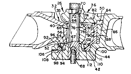
In Figures 2-4, articulated connection 26 is shown in
varying detail to include a male connecting member 32 having
a front end 33 attached in a fixed manner to inner end 22 of
first railway car body 12 and a rear or outer end 34 which
is received in an open front end 35 of an improved female
connecting member 36. Female connecting member 36
additionally has a rear end 38 attached in a fixed manner to
inner end 24 of second railway car body 13. Outer end 34 of
male connecting member 32 includes a vertical pin aperture
40. On a bottom 42 of female connecting member 36 is center
plate bearing surface 44 which forms the inserting portion
of a center plate joint 46. A corresponding center bowl 48
of center plate joint 46 is formed as part of bolster 28 of
railway truck 30 and receives center plate bearing surface
44 therein.
2Q223~5
As can additionally be seen in Figures 5 and 6, the
open front end 35 of female connecting member 36 leads to an
inner cavity 50. In a bottom bounding surface 52 of inner
cavity 50 is an annular groove 54 positioned about a
circular hub 56. Annular groove 54 is bounded by a floor
112 on its bottom and by concentric raised inner 57 and
outer walls 59 on its sides. A vertical circular aperture
58 extends through hub 56 and center plate bearing surface
44. Aperture 58 aligns with a second vertical circular
aperture 60 extending through a top portion 62 of open front
end 35 of female connecting member 36. A vertical primary
pin 64 extends through apertures 58 and 60 in female
connecting member 36 and through aperture 40 in male
connecting member 32 forming a movable joint 66 between male
connecting member 32 and female connecting member 36. A
lower end of primary pin 64 is formed having a cylindrical
cutout 67 to accommodate an upper end of a center pin 68,
the lower end of which extends into center bowl 48 of center
plate joint 46 on bolster 28. Primary pin 64 is secured
against undesired vertical movement by a horizontal
retaining pin 69 which passes through a horizontal aperture
70 in the top portion 62 of female connecting member 36.
Retaining pin 69 also passes through an annular notch 72
located about the perimeter of primary pin 64 which permits
rotation of primary pin 64 while providing against
unintentional removal of primary pin 64 during use.
2~22~5~
Movement between male connecting member 32 and female
connecting member 36 is regulated in part by a pin bearing
block 74 which is located within aperture 40 in male
connecting member 32 between primary pin 64 and an end wall
76 of rear outer end 34 of male connecting member 32. The
surface 78 of pin bearing block 74 which abuts end wall 76
is convex-shaped to correspond to the concave-shaped surface
80 of end wall 76. These corresponding shaped surfaces
provide for vertical angling movement of male connecting
member 32 relative to female connecting member 36.
In addition, movement between male connecting member 32
and female connecting member 36 is regulated in part by a
follower 82 and a wedge shim 84 which are located between
end wall 76 of male connecting member 32 and an innermost
surface 86 of inner cavity 50 of female connecting member
36. The surface 88 of follower 82 which abuts end wall 76
is concave-shaped to correspond to the convex-shaped surface
90 of end wall 76. These corresponding shaped surfaces
provide for both horizontal and vertical angling movement of
male connecting member 32 relative to female connecting
member 36. The wedge shim 84 provides for a slack-free
connection. As in-service wear occurs, end wall 76 of male
connecting member 32 tends to move away from surface 86 of
inner cavity 50 of female connecting member 36. During such
movement, wedge shim 84 drops to take up slack.
Movement between male connecting member 32 and female
connecting member 36 is further regulated by a spherical
2~223~i~
ring 92 and ring seat 94, spherical ring 92 having an outer
bottom radiused surface 96 complementary with an outer top
radiused surface 98 on ring seat 94 for movement within ring
seat 94. These complementary surfaces provide for
horizontal and vertical angling movement as well as
rotational movement between male connecting member 32 and
female connecting member 36. Spherical ring 92 and ring
seat 94 are received within annular groove 54 about hub 56
in female connecting member 36. An undersurface 110 of ring
seat 94 meets the floor 112 of annular groove 54. A top
surface 100 of ring 92 engages a flat undersurface 102
formed about aperture 40 in male connecting member 32.
While the railway vehicle is in service, wearing away
of the metal occurs in surfaces 100 and 102 and to a greater
extent in surfaces 96 and 98 resulting in the lowering of
male connecting member 32 and car body 12 to which it is
secured. Consequently, a corresponding decrease in the
restrictive space allocated for side bearing (not shown)
clearance occurs which is below the minimum standard set by
the American Association of Railroads. One way to restore
male connecting member 32 to an acceptable height is to
place an annular shim 104 within annular groove 54
underneath undersurface 110 of ring seat 94 (as shown in
Figure 7). This is done by disconnecting male connecting
member 32 from within female connecting member 36 and
lifting ring 92 and ring seat 94 from within annular groove
54, placing shim 104 within annular groove 54 and replacing
2~223~
ring 92 and ring seat 94 over top shim 104. Lifting ring
seat 94 from annular groove 54 is often made difficult by
the lodging of ring seat 94 within said annular groove 54
due to the accumulation and solidification of lubricant,
dirt and debris between the outer perimeter 111 of ring seat
94 and outer wall S9 of annular groove 54.
It has been found that restoration is facilitated by a
method of ejecting ring seat 94 from annular groove 54,
after first withdrawing male connecting member 32 from
female connecting member 36, by applying or transmitting an
upwardly directed force against the undersurface 110 of ring
seat 94 from one or more locations outward of female
connecting member 36. In this manner, physical impediments
to removal are readily overcome and ring seat 94 is
propelled out of annular groove 54.
Such a force may be applied by providing an access
passageway 106 between locations on an outer portion 107 of
annular groove 54 normally covered by ring seat 94 and an
exterior surface 108 of female connecting member 36, and
inserting a tool 116 against undersurface 110 of ring seat
94. In accordance with the location and attitude of access
passageway 106, a sufficient force to eject ring seat 94 may
be applied by wedging between undersurface 110 of ring seat
94 and floor 112 of annular groove 54, by levering or prying
surfaces 110 and 112 apart, or by pushing upwardly against
undersurface 110 thereof.
2~223S~
An apparatus for performing the foregoing method
comprises an ejecting means extending between an exterior
surface 108 of female connecting member 36 and outer wall
107 of annular groove 54. It is important that the ejecting
means be located in an area of annular groove 54 that is
normally covered by ring seat 94. It is additionally
convenient to locate the ejecting means in an area of
exterior surface 108 at a level above the portion inserted
within center bowl 48 so as to be exposed for the
application of an ejecting force without need to remove
female connecting member 36 from center bowl 48
(''detrucking'' is unnecessary). The ejecting means may take
the form of one or more access passageways 106 extending
from front exterior surface 108 of center plate 44 to outer
wall 107 of annular groove 54 permitting insertion of a tool
116 against an undersurface 110 of ring seat 94. Access
passageway 106 is most conveniently located at front open
end 35 of female connecting member 36 which becomes fully
exposed upon removing male connecting member 32.
Once male connecting member 32 is disconnected from
female connecting member 36, ring 92 and ring seat 94 may be
ejected from angular groove 54 by inserting tool 116 in
access passageway 106 in a number of different ways. For
example, Figure 8 shows tool 116 as a hardened tapered
chisel point which is wedged between undersurface 110 of
ring seat 94 and floor 112 of annular groove 54 and either
pushed straight in wherein the natural taper of tool 116
-- 10 --
2~223~
provides an upward force to undersurface 110 of ring seat 94
to eject ring seat 94 or, if necessary, tool 116 may be
pushed downward in a lever-like motion thus ejecting ring
seat 94 from annular groove 54.
An alternative method of ejecting ring seat 94 is shown
in Figure 9 in which a tool 128 such as a screwdriver is
wedged between undersurface 110 of ring seat 94 and floor
112 of annular groove 54 and rotated providing a similar
upward force to pry undersurface 110 of ring seat 94 from
floor 112 of annular groove 54.
Another alternative method is shown in Figure 10 in
which access passageway 117 extends at an angle from front
exterior surface 132 of female connecting member 134 to the
floor 136 of angular groove 138 and a tool 140 such as a
punch is inserted in access passageway 117 to undersurface
141 of ring seat 142. Tool 140 is then pushed straight in
providing an upward force on undersurface 110 of ring seat
142, thus ejecting ring seat 142 from annular groove 138.
It is preferred that passageway 106 be substantially
horizontal at a level in which the center point of
passageway 106 is at the same vertical height as that at
which undersurface llO of ring seat 94 meets floor 112 of
annular groove 54. Alternatively, the access passageway may
be offset so as to extend at an angle from front exterior
surface 108 to annular groove 54. By way of example, an
access passageway 117 is shown to extend at a vertical
offset in the alternative embodiment of Figure 10.
2~2235~
While access passageway 106 may be located at any
position in female connecting member 36 and be directed in
any such way which will provide for insertion of tool 116 to
apply an upward force to undersurface 110 of ring seat 94
to, in turn, eject ring seat 94 from annular groove 54, it
has been found that stress conditions are most favorable
when access passageway 106 is located in front exterior
surface 108 of female connecting member 36 at a 45 angle
radially from longitudinal centerline A-A of railway car
bodies 12 and 13. In addition, stress conditions are most
favorable when the center line of access passageway 106 is
positioned to be directed through the center of hub 58.
Alternatively, ~ second access passageway 118 may be
located in front exterior surface 108 of female connecting
member 36 at a 45 angle radially from the longitudinal
centerline A-A but on the opposite side of centerline A-A
from access passageway 106. This provides for the insertion
of a second tool (not shown) resulting in a greater upward
force to undersurface 110 of ring seat 94 in the case of a
ring seat 94 which is extremely difficult to dislodge from
annular groove 54. Furthermore, second access passageway
118 provides a convenient alternative point of insertion of
a tool in the case where access from either side of
centerline A-A is desired.
The preferred embodiment of the invention consists of
an access passageway 106 with a circular cross section which
provides for ease and lower cost of manufacturing. In the
- 12 -
2~2Z3~5
alternative, an access passageway may be of any shape
desired. For example, Figure 11 shows a centerplate bearing
surface 120 of a female connecting member 122 including
access passageway 123 extending from front exterior surface
124 to annular groove 126 and having a rectangular slot-like
configuration which may be preferred for a corresponding
shaped tool (not shown) to be used to lift a ring seat (not
shown) from annular groove 126.
The foregoing description and drawings explain and
illustrate the best known mode of the invention and those
skilled in the art who have the disclosure before them will
be able to make modifications and variations therein without
departing from the scope of the invention which is defined
in the following claims.