Note: Descriptions are shown in the official language in which they were submitted.
202288~
ANIMAL TRAP
BACKGROUND OF THE lNV~NllON
Field of the Invention (Technical Field):
The invention described and claimed herein is generally related to
traps for catching small animals, such as mice or other small rodents.
More particularly, the present invention is related to those animal
traps having a spring-loaded, bail-type striker which is cocked upon
being set, and which upon release by a triggering mechanism strikes and
typically kills the animal.
Description of the Related Art Including Information
Disclosed under 37 C.F.R. 1.97-l.99 (Background Art):
Many animal traps having a bail-type striker are typically set by
a two step process, involving first cocking and latching the bail-type
striker, followed by the setting of a baited triggering mechanism. This
process is typically awkward and difficult for several reasons. One
reason is that the triggering mechanism must be set while the trap is
held cocked, a process that is awkward in and of itself even with two
hands. Typically the trap must be held cocked with one hand while the
other hand sets the triggering me~h~ni! , with the latter step being
somewhat difficult to perform with only one available hand.
Another disadvantage common to many of the previously available
traps is that the trigger mechanism of the trap must be manually set
while the bail-type striker is held cocked, but not latched, and with
the fingers in the path of the striker. This occurs because the
triggering mechanism typically lies within the path of the striker. The
setting process is thus at the very least awkward, and not infrequently
leads to the trap being sprung on the fingers while it is being set,
causing pain and even injury to the fingers.
Yet another disadvantage of many previously available traps is
that the trigger mechanism is not sufficiently sensitive to be entirely
reliable. Some trigger mechanisms are actuated only when an animal
pulls or pushes a piece of bait in a particular direction, but is not
actuated when the animal pushes or pulls the bait in all directions.
Consequently, it is possible under some circumstances for an animal to
remove the bait without triggering the trap.
r4~
2022~89
U.S. Patent No. 4,360,986, to Dushey, discloses a bail-type animal
trap which is intended to allow setting without exposing the fingers to
the bail. However, the trap disclosed in Dushey suffers from the common
disadvantage noted above of being triggered only by the bait being
depressed downwardly, and is not triggered when the bait is pushed or
pulled in other directions.
U.S. Patent No . 4,711,049, to Kness, discloses an animal trap
which is also intended to allow setting without exposing the fingers to
the bail. The trap disclosed in Kness also suffers however from the
disadvantage noted above of only being triggered by downward depression
of the bait.
U.S. Patent No . 4,574,519, to Eckebrecht, discloses a mouse trap
having a novel combined trip bar and holding member, for preventing
injury to the fingers during setting of the trap.
U.S. Patent No . 1, 458,404, to Goodman, discloses a rat trap which
is also designed to avoid injury to the finger upon setting the trap.
U.S. Patent No. 1,462,102, to Dodson, discloses a trap having a
trigger mechanism that is located primarily on the underside of the
traps, but which is actuated only by downward pressure on a bait holder.
SUMMARY OF THE lNV~NLlON
(DISCLOSURE OF THE INV~NLlON)
The present invention provides an improved animal trap which is
automatically self-setting and easily actuated. The preferred animal
trap of the invention comprises a generally flat base comprising a
forward end and a rear end; a bail-type striker hinged to the base for
relative swinging motion on the base between a cocked position at the
rear end of the base and a sprung position at the forward end of the
base; spring means for driving the striker from the cocked position at
the rear end of the base to the sprung position at the forward end of
the base; resilient latch means affixed to the rear end of the base and
extending upwardly therefrom, the latch comprising means operable to
engage and retain the striker in the cocked position, and the latch
means being resiliently disposed toward the rear end of the base so as
202~
-
to release the striker except when urged toward the forward end of the
base; a trigger plate comprising an integral downwardly protruding catch
and integral fulcrum means, the trigger plate further comprising means
for ret~ining a piece of bait placed thereon; connecting means
connecting the latch means to the trigger plate; and stop means affixed
to the base, the stop means being engagable with the catch of the
trigger plate, and the trigger plate, when engaged with the stop means,
operating through the connecting means to urge the latch means toward a
forward position ret~ining the striker in the cocked position. The
trigger plate may be disengaged from the stop means upon the trigger
plate being depressed downwardly, being lifted upwardly or being moved
sideways, by an animal, so as to thereby release the latch means and
allow the striker to be driven to the sprung position. In the preferred
animal trap of the invention, the bail-type striker comprises a heavy
gauge wire formed into a generally rectangular configuration having four
integral segments, one of the segments being an axial segment about
which the striker rotates.
The animal trap further comprises a self-setter. The preferred
self-setter comprises an elongate plate extending transversely from the
axial segment of the striker and oriented so as to urge the trigger
plate into engagement with the stop means upon the striker rotating from
the cocked position to the sprung position. In an alternative
embodiment, the self-setter comprises a resilient cross-bar affixed to
and extending across the striker, wherein the cross-bar is oriented so
as to urge the trigger plate into engagement with the stop means upon
the striker rotating from the cocked position to the sprung position.
In the preferred embodiment, the connecting means may comprise a
wire or rod extending between the trigger plate and the latch means.
The latch means preferably comprises a resilient plate extending
upwardly from the base, the resilient plate comprising an integral catch
extending forwardly from the plate. The stop means preferably comprises
a staple fully driven into the base so as to form a rigid stop
positioned close to the surface of the base. The integral fulcrum means
of the trigger plate may comprise an integral dent punched into the
trigger plate from its upper surface or a downwardly extending curve in
the trigger plate. The integral downwardly extending catch of the
trigger plate preferably comprises a downwardly punched section of the
2~22~89
plate, the downwardly punched section being formed by first forming a
punched transverse slit in the trigger plate, followed by punching
downwardly a segment of the plate immediately forward of the slit. The
catch means extending forwardly of the resilient plate of the latch
means preferably comprises a forwardly punched segment of the resilient
plate, the forwardly punched segment being formed by first forming a
transverse slit in the resilient plate, followed by punching forward a
segment of the resilient plate above the slit from the rear side of the
resilient plate.
Accordingly, and in view of the foregoing, it is an object and
purpose of the present invention to provide an improved animal trap
which can be set without significant risk of the trap being sprung on
the fingers while being set.
It is another object and purpose of the present invention to
provide an animal trap which is automatically self-setting when the trap
is cocked.
It is yet another object of the present invention to provide an
animal trap which is characterized by a trigger mechanism that is
actuated regardless of the direction in which a piece of bait is pushed
or pulled by an animal.
Other objects, advantages and novel features, and further scope of
applicability of the present invention will be set forth in part in the
detailed description to follow, taken in conjunction with the
accompanying drawing, and in part will become apparent to those skilled
in the art upon examination of the following, or may be learned by
practice of the invention. The objects and advantages of the invention
may be realized and attained by means of the instrumentalities and
combinations particularly pointed out in the appended claims.
These and other aspects of the present invention will be more
apparent upon consideration of the accompanying drawings and the
detailed description set forth below.
2022~
BRIEF DESCRIPTION OF THE DRAWINGS
The accompanying drawings form a part of and are incorporated by
reference into this specification. The drawings, when taken with
detailed description of the invention set forth below, serve to
illustrate certain preferred embodiments of the invention and the best
mode contemplated by the inventor of making the present invention.
In the drawings:
FIGURE 1 is an isometric view of the animal trap of the present
invention in the cocked, or set, position;
FIGURE 2 is a plan view of the animal trap of Figure 1 in the
sprung, or unset, position;
FIGURE 3 is a plan view of the animal trap of Figure 1 in the
cocked, or set, position;
FIGURE 4 is a side view of the animal trap of Figure 1 in the
sprung position;
FIGURE 5 is a side view of the animal trap of Figure 1 in the
cocked, or set, position;
FIGURE 6 is an end view of the trap in the uncocked, or sprung,
position;
FIGURE 7 is an isometric view of an alternative preferred
embodiment of the present invention;
FIGURE 8 is a partially cut-away isometric view of the trigger
plate of the trap; and
FIGURE 9 is a side view in cross-section of the trigger plate.
DETAILED DESCRIPTION OF THE PREFERRED EMBODIMENTS
OF THE INVENTION (BEST MODES FOR CARRYING OUT THE lNV~NLlON)
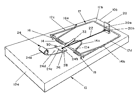
Referring to Figures 1 through 6, the preferred embodiment of the
animal trap of the present invention comprises a substantially solid
2022~9
_
rectangular base 10. Mounted on the upper side of the base 10 is a
spring-loaded bail-type striker 12. The striker 12 consists of a length
of heavy gauge material, such as steel wire, which is bent into a
generally rectangular configuration having four straight segments 12a
S through 12d, with one end of the length of wire preferably looped about
the opposite end to complete the rectangular configuration. The
striker 12 comprises a straight axial segment 12a about which the
striker 12 rotates in, swinging from a cocked position to a sprung
position. The straight axial segment 12a is encircled by a coil
spring 14 which drives the striker 12 and urges it toward the uncocked,
or sprung, position, illustrated in Figures 2 and 4. The coil spring 14
and the straight axial segment 12a are maintained in a fixed position
extending across the center of the base 10 by means of a pair of heavy
hinge staples 16 and 18, preferably u-shaped staples, which extend over
the straight segment 12a at opposite ends of the spring 14, and which
are affixed in the base 10 and function as journal bearings for the
axial segment 12a. The spring 14 comprises opposite end arms 14a
and 14b which extend generally transversely to the axis of the spring
and which engage the opposite side segments 12c and 12d of the
striker 12. The coil spring 14 further comprises an integral central
portion 14c which extends outwardly and downwardly, and which is urged
against the base 10 so as to maintain a suitable level of tension in the
spring 14. In operation, it is the outer segment 12b of the striker 12
which strikes and kills an animal upon the trap being sprung.
For the purposes of this description, the end of the trap at which
the outer end 12b of the striker 12 rests while in the uncocked
position, shown in Figures 2, 4 and 7, will be referred to as the
forward end lOa of the trap, and the opposite end will be referred to as
the rear end lOb of the trap. This orientation will also be used with
reference to various elements of the trap.
The striker 12 is retained in the cocked position, as shown in
Figures 1, 3 and 5, by means of a latch 20. The latch 20 consists of a
planar strip, such as a steel strip, that extends upwardly through a
slot in the base 10. The lower end of the latch 20 is folded under the
underside of the base 10 and is stapled thereto by a staple 21, as shown
in Figures 4, 5, and 6, so as to prevent the latch 20 from being pulled
upwardly from the base 10. The latch 20 extends upright from the slot
7 ~22~8~
and comprises an integral striker catch 20a which is formed by means of
a protruding, punched notch. More specifically, the catch 20a is made
by first forming a transverse slit in the latch 20, followed by punching
forward a segment of the latch strip just above the slit, so as to form
the protruding catch 20a having a downwardly facing angular edge. When
the striker 12 is positioned in the cocked position, shown for example
in Figure 1, the catch 20a of the latch 20 may be extended over the
outer segment 12b of the striker 12 so as to retain the striker 12 in
the cocked position.
The latch 20 further comprises a hole 20b, located below the
catch 20a, which receives a first end of a trigger wire 22. The trigger
wire 22 extends through the hole 20b in the latch 20 and is wrapped
around the latch 20 to firmly secure the first end of the trigger
wire 22 to the latch 20. In an alternative embodiment, not shown, the
"wire" may be a rod, such as a-steel rod, which engages with a slot in
the latch 20. Such an embodiment is useful for large rodents, such as
rats. The invention is not limited to the particular trigger mech~ni
shown in the drawings.
The opposite or forward end of the trigger wire 22 is affixed to
the rear end of a trigger plate 24, which is shown more particularly in
Figures 8 and 9. The trigger plate 24 functions in a dual capacity as a
bait holder and as a trigger which actuates the trap. The trigger
plate 24 preferably comprises a rigid arcuate strip, folded upwardly and
backward at its forward end 24a to assist in holding bait, although
other end shapes are useful in accordance with the invention. At the
rear end of the plate 24 is a hole 24b by which the trigger wire 22 is
affixed to the plate 24. The plate 24 also comprises an integral
trigger catch 24c, which is formed as a downwardly punched protrusion,
and which is formed in essentially the same manner as the catch 20a of
latch 20. More specifically, the catch 24c is formed by first forming a
transverse slit in the plate 24, followed by punching the plate 24
downwardly on the forward side of the slit, so as to form the downwardly
protruding catch 24c having a rearwardly facing edge. The trigger
plate 24 also preferably comprises a downwardly protruding dent 24d,
which is located forward of the catch 24c. The function of the dent 24d
is as described below. The trigger plate 24 is preferably curved
concavely upwardly, for the reasons discussed below.
8 202~89
The latch 20 is made sufficiently resilient such that when
striker 12 is in the cocked position and therefore retained by the
latch 20, the tension in the trigger wire 22 or rod is maintained by
the resiliency of the catch 20. Latch 20 is resiliently disposed
toward rear end lOb of base 10 so as to release striker 12, except when
urged toward forward end lOa of base 10.
The catch 24c of the trigger plate 24 engages a staple 26,
preferably a round staple, which is driven completely into the base 10
until the top of the staple 26 thus forms a rigid stop, against which
the catch 24d of the trigger plate engages to hold the striker 12 in
the cocked position. Stop 26 is thus affixed to base 10 and engageable
with catch 24c of trigger plate 24. Trigger plate 24, when engaged
with stop 26, operates through connecting means or trigger wire 22 to
urge latch 20 toward a forward position, retaining striker 12 in the
cocked position.
The downwardly protruding dent 24d in the trigger plate 24
functions as a lever and integral fulcrum, to cause the catch 24c of
the trigger plate 24 to be lifted upwardly and free of the staple 26
when the forward end 24a of the plate 24 is pressed downwardly by an
animal. Although the dent 24d is preferable, a trigger plate 24 curved
downwardly in this area will also function as a lever and integral
fulcrum. The trigger plate 24 is preferably curved concavely upwardly
so as to enable it to pivot about the end 24c. It will be noted that
the catch 24c will also release from the staple 26 when the forward end
24a of the trigger plate 24 is lifted upwardly by an animal. Thus it
will be apparent that one of the primary advantages of this aspect of
the invention is that the trigger plate 24 will be released from
engagement with the staple 26 either when the folded end 24a of the
plate 24, bearing the bait, is lifted upwardly, depressed downwardly,
or moved sideways. This results in increased sensitivity over similar
animal traps previously available.
The trigger plate 24 is preferably bent slightly upwardly at its
rear end, between the trigger wire hole 24b and the catch 24c, so that
when the trigger wire 22 pulls on the trigger plate 24, the plate tends
to pivot upwardly and more readily release from the stop 26.
A pair of small hooked pegs 28 and 30, each preferably having a
curved upper end, is embedded in the base 10 on opposite sides of the
trigger plate 24, just rearward of the staple 26. The curved upper
ends of the pegs 28 and 30 are oriented so as to extend over the
trigger plate 24 and retain the plate 24 in the general vicinity of the
staple 26. The pegs 28 and 30 do not firmly engage the trigger
plate 24, but rather simply limit the range of lateral and upward motion
2~228~9
of the trigger plate, with the trigger wire 22 operating to keep the
trigger plate from moving forward, and the staple 26 and folded end 24a
of the trigger plate operating to retain the plate 24 from moving too
far rearward.
S The trap further comprises a self-setter 32, which in the
preferred embodiment comprises a narrow elongate plate which extends
forwardly and downwardly from the axial segment 12a of the striker 12
when the striker 12 is in the sprung position shown in Figure 1. In the
sprung position shown in Figure 2, the self-setter 32 bears gently upon
the trigger plate 24 so as to urge the trigger plate 24 into engagement
with the staple 26. Thus the trap is generally set automatically by the
self-setter 32 each time the trap is sprung. It will be noted that the
self-setter 32 is short and is oriented at an angle with respect to the
striker 12, such that the self-setter 32 does not significantly di ini .sh
the strength of the spring 14 in driving the striker 12.
Figure 7 illustrates an alternative preferred embodiment for the
self-setter. In Figure 7, elements which are substantially identical to
elements shown in Figures 1 through 6 are like-numbered. In the
embodiment shown in Figure 7, the alternative self-setter comprises a
resilient, downwardly concave cross-bar setter 34, preferably made of
metal. The cross-bar setter 34 is affixed to the side segments 12c
and 12d of the striker 12. The cross-bar setter 34 urges the trigger
plate 24 downwardly and forwardly when the trap is in the uncocked, or
sprung, position, so as to set the trigger plate 24.
It will be appreciated that the present invention has been
described above with reference to a preferred embodiment and an
alternative preferred embodiment. However it will also be apparent that
various modifications, substitutions and alterations, which may be
apparent to one of ordinary skill in the art, may be made without
departing from the essential invention.