Language selection

Search

Patent 2023045 Summary

Third-party information liability

Some of the information on this Web page has been provided by external sources. The Government of Canada is not responsible for the accuracy, reliability or currency of the information supplied by external sources. Users wishing to rely upon this information should consult directly with the source of the information. Content provided by external sources is not subject to official languages, privacy and accessibility requirements.

Claims and Abstract availability

Any discrepancies in the text and image of the Claims and Abstract are due to differing posting times. Text of the Claims and Abstract are posted:

  • At the time the application is open to public inspection;
  • At the time of issue of the patent (grant).
(12) Patent: (11) CA 2023045
(54) English Title: PIPE SUPPORT STAND
(54) French Title: SUPPORT POUR TUYAUX
Status: Expired and beyond the Period of Reversal
Bibliographic Data
Abstracts

English Abstract


PIPE SUPPORT STAND
Abstract of the Disclosure
A pipe support stand is provided which is a plastic
modular unit of a generally pyramidal shape. The unit has a
hollow interior to permit stackability. Four angled legs are
defined at each of its corners. A central substantially vertical
rib increases the mechanical strength and stability of the unit.


Claims

Note: Claims are shown in the official language in which they were submitted.

THE EMBODIMENTS IN WHICH AN EXCLUSIVE PROPERTY OF
PRIVILEGE ARE CLAIMED ARE DEFINED AS FOLLOWS:
1. A stand for supporting an elongate tubular member
which comprises:
- a hollow generally pyramidal-shaped modular body
formed of plastic, said body further defining a
generally arcuate recess on its upper surface
adapted to receive the tubular member therein, said
body forming four angled legs at the outer corners
thereof and a pair of central ribs on the front and
rear sides thereof and said body further having a
substantially continuous base forming an outwardly
extending rectangular lip.
2. The stand as set forth in claim 1 wherein said
central ribs are substantially vertical.

Description

Note: Descriptions are shown in the official language in which they were submitted.


- 202304~
1 FIELD OF THE INVENTION
2 The present invention relates to a support stand for
3 pipeline construction proJects.
4 sAcKGR UND OF THE INVENTION
During the construction and installation of a pipeline,
6 it is necessary to support the interconnected pieces of pipe
7 prior to its insertion into the ground. Up to the present time,
8 a typical pipe support stand comprised a wooden four-legged horse
g having a strap across the top. The strap defined a groove which
was adapted to receive the pipe. The disadvantages of these
11 prior art units resided in their heaviness, propensity to
12 breakage and the limited stackibility of the units.
13 There existed, therefore, the need for a pipe support
14 stand exhibiting the following characteristics.
- lightness in welght;
16 _ abillty to stack more than 3 or 4 units together
17 such as was the case wlth the above-descrlbed
18 prlor art unlts;
19 - unbreakabllity; and
- stablllty when ln use thus avoldlng the
21 posslblllty of damage to the pipe coatlng, which
22 would occur when the stand toppled over.
23 SUMMARY OF THE INVENTION
24 In accordance with the present lnventlon, there ls
provided a modular plpe support stand formed of a substantially
26 unbreakable sultable plastlc. Preferably, the plastic would
27 comprise polyethylene. A further advantage of using such a

202304~
1 material resides in the fact that the stand is of a light welght
2 (in the order of about seven pounds). A hollow interior i8
3 provided which means that as many as fourteen or more unit~ may
4 be stacked together at one time. A central rib provides
increased mechanical strength and stability to the stand.
6 Preferably, two substantially vertical ribs may be provided at
7 the centre of the stand, thus improving the strength and
8 stability thereof. A continuous base defining an outwardly
9 projecting lip still further increases the stability of the
stand.
11 In a broad aspect, the invention relates to a stand for
12 supporting an elongate tubular member which comprises:
- a generally pyramidially shaped modular body
14 formed of plastic, said body further forming a
hollow interior, said body further defining an
16 upper generally arcuate reaess on its upper
17 surfaoe adapted to receive the tubular member
18 therein, and forming four angled legs at the outer
19 corners thereof and a central rib on each side
thereof and said body further havlng a
21 substantially continuous base forming an outwardly
22 extending lip.
23 DESCRIPTION OF THE DRAWINGS
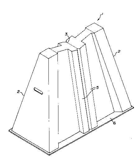
24 Figure l is a perspective view of the preferred
embodiment of the stand.
26 Figure 2 is a plan view taken from the base of the
27 stand.

" 202304~
l DESCRIPTION OF THE PREFERRED EMBODIMENT
2 Having reference to the accompanylng drawings, there is
3 provided a generally pyrlmidal pipe support stand 1.
The modular stand 1 is preferably formed of a
fluorescent 3/16" thick polyethylene.
6 The stand 1 defines four angled legs 2 at each of its
7 corners. A groove 3 formed on the upper surface of the stand 1
8 is adapted to receive the pipe 4. A pair of ribs 5 are formed in
g the central portion of the stand 1. At the base of the stand 1
there is provided an outwardly extending lip 6, the outer
ll perimeter of which is generally rectangular in shape.

Representative Drawing
A single figure which represents the drawing illustrating the invention.
Administrative Status

2024-08-01:As part of the Next Generation Patents (NGP) transition, the Canadian Patents Database (CPD) now contains a more detailed Event History, which replicates the Event Log of our new back-office solution.

Please note that "Inactive:" events refers to events no longer in use in our new back-office solution.

For a clearer understanding of the status of the application/patent presented on this page, the site Disclaimer , as well as the definitions for Patent , Event History , Maintenance Fee  and Payment History  should be consulted.

Event History

Description Date
Time Limit for Reversal Expired 1998-08-10
Letter Sent 1997-08-11
Grant by Issuance 1994-05-31
Application Published (Open to Public Inspection) 1992-02-10
All Requirements for Examination Determined Compliant 1991-01-07
Request for Examination Requirements Determined Compliant 1991-01-07

Abandonment History

There is no abandonment history.

Owners on Record

Note: Records showing the ownership history in alphabetical order.

Current Owners on Record
LYLE SCOTT
Past Owners on Record
None
Past Owners that do not appear in the "Owners on Record" listing will appear in other documentation within the application.
Documents

To view selected files, please enter reCAPTCHA code :


To view images, click a link in the Document Description column. To download the documents, select one or more checkboxes in the first column and then click the "Download Selected in PDF format (Zip Archive)" or the "Download Selected as Single PDF" button.

List of published and non-published patent-specific documents on the CPD .

If you have any difficulty accessing content, you can call the Client Service Centre at 1-866-997-1936 or send them an e-mail at CIPO Client Service Centre.


Document
Description 
Date
(yyyy-mm-dd) 
Number of pages   Size of Image (KB) 
Abstract 1994-07-08 1 11
Claims 1994-07-08 1 18
Drawings 1994-07-08 2 24
Description 1994-07-08 3 77
Representative drawing 1999-07-05 1 11
Maintenance Fee Notice 1997-09-30 1 179
Fees 1996-08-06 1 36
Fees 1996-01-22 1 40
Fees 1994-01-16 1 28
Fees 1995-02-08 1 40
Fees 1992-05-27 1 36
Prosecution correspondence 1991-01-06 1 37
Examiner Requisition 1992-03-26 1 58
Courtesy - Office Letter 1994-02-03 2 80
Prosecution correspondence 1992-05-04 2 66
PCT Correspondence 1994-01-16 2 31
Prosecution correspondence 1993-09-28 1 33
Courtesy - Office Letter 1992-02-18 1 50
Prosecution correspondence 1992-01-12 2 69
Courtesy - Office Letter 1991-05-08 1 21
Courtesy - Office Letter 1990-07-30 1 18
Prosecution correspondence 1991-01-06 1 28
Courtesy - Office Letter 1991-04-19 1 22
PCT Correspondence 1990-08-08 2 51