Note: Descriptions are shown in the official language in which they were submitted.
G-3,548 C-4,178
VARIABLE RELUCTANCE ROTATION SENSOR
Background of the Invention
This invention relates to a variable
reluctance rotation sensor which generates a high
output signal at very low rotational speeds. Such
a sensor would find particular utility in an vehicle
anti-lock braking or traction control, in which low
rotational speed sensing is required.
A variable reluctance rotation sensor of the
prior art may typically comprise a rotatable toothed
magnetic wheel and a stationary sensor unit having a
permanent magnet and apparatus establishing a main flux
loop including the permanent magnet and toothed wheel
and defining an air gap between a member of the sensor
unit and the closest tooth or teeth of the wheel. The
member defining the air gap may be a magnetic flux
member or the permanent magnet itself. The air gap
thus varies with rotation of the toothed wheel between
a small gap when the member is aligned with a tooth and
a larger gap when it is not. The main flux loop is
linked to all the turns of an electrical coil
surrounding the magnetic flux member; and an electric
voltage is generated in the coil proportional to the
rate of change of the flux linked thereto. As the
toothed wheel rotates, the total flux in the main flux
loop linked to the coil changes with the changing air
gap, as teeth and inter-teeth slots alternately pass
the stationary sensor unit; and an output electrical
signal is generated in a sinusoidal pattern, with a
~ ~ ~ ,f~J ~
maximum each time the member is aligned with a tooth
and a minimum each time it is aligned with a slot.
The amplitude of the signal in a variable
reluctance rotation sensor of the prior art varies with
such well known design factors as the energy product of
the permanent magnet and the minimum air gap size; and
good design in the prior art has tended to provide the
greatest magnetic energy from a magnet of a given size,
the smallest consistently producible minimum air gap
and the greatest possible concentration of main flux
through the tooth adjacent the magnet or flux member.
Although leakage flux, which escapes the main flux
path, is inescapable, the design tendency has been to
minimize it for the greatest possible percentage of
total magnetic flux in the main flux loop linked to the
entire coil. The recent use of new high energy product
magnetic materials has helped provide a high level of
magnetic flux from a small magnet in a limited space.
However, it is difficult to hold a tight minimum air
gap consistently in mass production at reasonable cost.
Also, the amplitude of the sensor signal decreases with
rotational speed, since the rate of change of flux due
to air gap variation decreases as the tooth moves more
slowly past the stationary member. Therefore,
inexpensive variable reluctance rotation sensors
generating a high output at very low rotational speeds
are not readily available.
In a vehicle anti-lock brake system, the
sinusoidal output of a variable reluctance rotation
sensor is filtered with a noise suppressing dead band.
A rotation is counted only if the sinusoidal peak of
the signal exceeds the deadband, with any signal event
2023700
within the deadband not accompanied by travel out of
the deadband being considered noise and ignored. The
greater the peak-to-peak signal level, the greater the
deadband can be established and the greater is noise
immunity. However, as rotational speed falls close to
zero RPM, the output of most available rotation sensors
falls to very low levels which can limit the usable
deadband and thus reduce noise immunity. This makes it
more difficult to use such sensors in anti-lock braking
systems.
Summary of the Invention
The variable reluctance rotation sensor of
this invention generates a higher output at very low
rotational speeds than those of the prior art and
therefore provides an improved rotational speed signal
for use in vehicle anti-lock braking and traction
control systems. In addition, the sensor of this
invention provides such a signal with a larger minimum
air gap than typical variable reluctance sensors of the
prior art. Whereas variable reluctance sensors of the
prior art are designed to sense variations in the total
flux level in the main flux loop linked to the entire
electrical coil, the variable reluctance sensor of this
invention relies more on changes in spatial flux
distribution to vary the linkages of flux to individual
coil turns. It accomplishes this by establishing
substantial flux loops, normally considered leakage
flux, which are separate for each magnet and which
include return paths crossing the air gap from the flux
member to the toothed wheel between the magnets so as
to be linked to a variable number of the total turns of
the electrical coil wrapped around the flux member. We
4 2023700
have discovered that this approach produces a
significantly more sensitive sensor with a higher
output than can be obtained from the traditional prior
art apparatus, especially at low rotational speeds and
with a larger minimum air gap.
Our publication "Variable Reluctance Sensor,"
Research Disclosure #29634, December 1988, shows a
variable reluctance sensor using a pair of permanent
magnets, each mounted adjacent the toothed wheel and
having opposite poles facing the teeth. The magnets
are spaced circumferentially so as to be simultaneously
aligned with teeth or slots as the wheel turns. A flux
member joins the other poles of the magnets in series
aiding relationship to create a common main flux path
through both magnets and the toothed wheel; but the
flux member extends adjacent the toothed wheel to
provide significant additional flux loops for each
magnet which cross the air gap between the flux member
and wheel between the magnets and enclose only some of
the turns of an electrical coil surrounding the flux
member. These additional flux loops are affected by
passing alternating teeth and slots between the magnets
to fluctuate circumferentially and thus vary the flux
linkages to individual turns of the coil. The result
is a greater output signal over that obtained from main
air gap variation in the common flux loop alone, as in
standard prior art sensors.
However, we have discovered that the sensor
of the invention disclosed herein, which is also based
on changing flux distribution rather than on changing
of flux level in the main flux loop, is superior even
to the sensor of the previously identified publication,
2023700
although this is not predicted by conventional theory
based only on main air gap variation of total flux
levels. The sensor of this invention uses a similar
arrangement of two magnets and a flux member extending
adjacent the toothed wheel to provide flux loops
enclosing only some of the coil turns; but there are
two differences: (1) the magnets have poles oriented in
series opposing relationship - that is, with similar
rather than opposite poles adjacent the toothed wheel -
and (2) the magnets are spaced circumferentially sothat, when one is aligned with a tooth of the wheel,
the other is aligned with a non-adjacent slot. The
first of these differences determines that there is no
common main flux loop including both magnets. Rather,
each magnet sets up its own flux loops; and the
majority of flux is distributed across the air gap
between the magnets to enclose only part of the coil.
Thus, the additional flux paths of the previously
identified publication are increased in the apparatus
of this invention, wherein they are the main flux
paths. The second of these differences determines that
the contributions of the variations in flux from the
two magnets will vary periodically in opposite phase
with the passage of teeth and will therefore be
additive across the coil.
The invention is a variable reluctance
rotation sensor comprising a magnetic toothed wheel
having teeth evenly spaced by slots around the
periphery thereof and being rotatably supported with
respect to a fixed magnetic pickup assembly. The
pickup assembly comprises a pair of permanent magnets
each having a pair of poles with a similar one of its
2~t~ 7~
pair of poles adjacent the toothed wheel: that is, both
magnets have north poles, for example, adjacent the
wheel. The permanent magnets are separated from each
other circumferentially around the periphery of the
toothed wheel by an arc equal to the arc between one of
the teeth and a non-adjacent slot, whereby the first
and second permanent magnets are alternately and
opposingly aligned with teeth and slots as the toothed
wheel rotates.
The magnetic pickup assembly further comprises
a magnetic flux member with a multi-turn electrical
coil wound thereon, the flux member joining the other
of the poles of the first and second permanent magnets
in series opposed relationship and extending between
the permanent magnets in close proximity to the toothed
wheel to establish separate, oppositely directed flux
loops for each of the permanent magnets distributed
along the magnetic flux member. The flux loops are
variably spatially determined by the position of teeth
and slots adjacent the magnetic flux member between the
permanent magnets and thus fluctuate circumferentially
across the coil with passing alternating teeth and
slots as the wheel rotates to generate an electrical
signal in the electrical coil by variation of flux
linkages to individual coil turns with wheel rotation.
In the sensor of this invention, the changes
in flux spatial distribution due to the passing teeth
and slots in the region between the magnets, with
consequent changes in flux linkages to individual coil
turns, appear to g-reatly increase the rate of change in
flux at low rotational speeds over that which would be
produced by the change in total flux at the air gap of
h,; ~..,~` ~ P'~ ~ } ''~J~
a main flux loop. The invention thus provides an
advantage over the prior art in maximizing the
utilization of additional flux loops normally
considered leakage flux to be minimized in prior art
sensors.
The variation in flux linkages to individual
coil turns is made possible by the use of two permanent
magnets, each of which has separate north and south
poles and can thus support separate flux loops, and by
the proximity of the magnetic flux member to the
toothed wheel, which helps establish significant flux
loops cutting across the coil between the magnets. The
amount of flux affected is maximized by arranging the
magnets in series opposed relationship to eliminate a
common main flux loop, create an opposing and therefore
additive phase relationship between the flux loops of
the two magnets, and ensure that a majority of flux
loops are distributed along the coil linked to a
variable number of coil turns. Although not required
for all embodiments of this invention, a preferred
embodiment places the magnets sufficiently far apart
that there are always several teeth of the wheel
between the magnets. These teeth are in close
proximity to the flux member and help concentrate the
flux loops for circumferential fluctuation with wheel
rotation. Further details and advantages of this
invention will be apparent from the accompanying
drawings and following description of a preferred
embodiment.
Summary of the Drawings
Figure 1 shows, partly in section, a variable
reluctance rotational speed sensor according to this
invention.
Figure 2 shows a schematic view of a sensor
accordiny to this invention, including magnetic flux
lines to demonstrate the total flux pattern.
Figure 3 shows an enlarged schematic view of a
sensor according to this invention, including magnetic
flux loops having return paths cutting across the coil
between the magnets, with the solid flux lines showing
the flux pattern when one of the magnets is adjacent a
tooth and the broken lines showing the flux pattern
when the other of the magnets is adjacent a tooth.
Description of the Preferred Embodiment
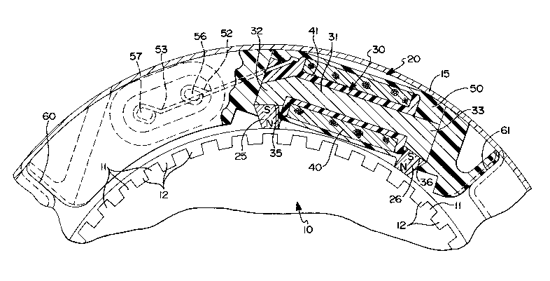
Referring to Figure 1, a toothed wheel 10 is
rotatably mounted in, for example, the wheel housing of
a vehicle equipped with an anti-lock braking system.
Magnetic toothed wheel 10 is engaged for rotation with
one of the vehicle road wheels, the rotational speed of
which is required. Toothed wheel 10 comprises, at its
outer peripheral edge, a plurality of rectangular teeth
11 separated by slots 12. Teeth 11 are evenly spaced
by slots 12 around the periphery or circumference of
wheel 10 and are substantially identical in size and
shape. Such toothed wheels are themselves well known
in rotational speed sensing equipment.
Toothed wheel 10 is enclosed within a cover
15, which also encloses a sensor unit 20. Cover 15 may
be, although not necessarily, a grease cover for a
wheel bearing unit. Sensor unit 20 is molded in a
thermoplastic housing press fit into a suitably formed
recess in cover 15; although it could be welded or
otherwise attached to the wheel cover by means of
mounting brackets extending out of the molded housing
50, if desired. In either case, sensor unit 20 is
fixed in a stationary position adjacent teeth 11 of
wheel 10 so that teeth 11 and slots 12 of wheel 10
alternately pass sensor unit 20 as wheel 10 rotates.
Sensor unit 20 comprises a pair of permanent
magnets 25 and 26 adjacent wheel 10, each of magnets 25
and 26 having a north pole and a south pole at opposite
ends thereof. Magnets 25 and 26 are shown as
trapezoidal in shape. This provides assembly
advantages, in that the shape contributes to their
being more easily held in the thermoplastic housing 50.
However, this is obtained at the cost of more magnet
mass and material than a rectangular magnet of
equivalent energy product. Permanent magnets 25 and 26
are oriented with their poles radially aligned with
wheel 10, so that similar poles of each of magnets 25
and 26 form air gaps with alternating teeth 11 and
slots 12 of wheel 10 as the latter rotates. For
example, in this embodiment, both magnets 25 and 26
have north poles adjacent wheel 10. Magnets 25 and 26
are spaced circumferentially around the periphery of
wheel 10 by an arc equal to that between a tooth and a
non-adjacent slot, so that, when one of magnets 25 and
26 is adjacent a tooth of wheel 10, the other is
adjacent a slot with at least one other tooth between
the magnets. In the preferred embodiment shown, there
will be several teeth between the magnets, as seen with
teeth llb, llc and lld in Figure 2; and these teeth, as
will be describe at a later point, will concentrate the
flux of the return paths and thus help cause the flux
loops to fluctuate circumferentially as wheel 10
rotates.
~ e ~
Sensor unit 20 further comprises a magnetic
flux member 30, which comprises a long straight portion
31 with short pole portions 32 and 33 perpendicular to
straight portion 31 at the two ends thereof. Pole
portion 32 has a slanted end surface 35 to which the
south pole of permanent magnet 25 is affixed, the slant
of the surface providing the required radial
orientation of magnet 25 relative to wheel 10.
Similarly, pole portion 33 has a slanted end surface 36
to which the south pole of magnet 26 is affixed to
provide the required radial orientation of magnet 26
relative to wheel 10. Straight portion 31 of flux
member 30 extends adjacent wheel 10 between magnets 25
and 26. Straight portion 31 does not have to be
perfectly straight, as long as it extends close to
wheel 10 between the magnets 25 and 26. However, a
straight portion seems to work well, due to the fact
that the curvature of the wheel brings it closer to
straight portion 31 near the center of the latter; and
it is easy to manufacture.
Magnetic flux member 30 is made of a magnetic
material such as steel. The arrangement of the poles
of magnets 25 and 26 is in series opposing
relationship. Thus, no common main magnetic flux loop
is established through both magnets. Rather, each of
magnets 25 and 26 establishes its own separate flux
loops, as shown in Figure 2. For each magnet, a large
percentage of the flux is contained in loops which can
be traced from the south pole of the magnet through
part of the straight portion 31 of flux member 30,
across a large air gap to wheel 10, and back through
wheel 10 and a smaller air gap to the north pole of the
ll
magnet. Since there is a large air gap in the return
path of each of these flux loops, one expects that the
total flux levels will be lower than would be the case
if a single flux path were established through both
magnets and the total length of flux member 30 by
series aiding magnets. However, comparing the same two
arrangements, that of this invention will provide the
greater flux in loops having return paths leaving flux
member 30 and cutting across to wheel 10 between the
magnets and thus the most flux available for spatially
distributional changes as wheel 10 rotates.
Figure 3 show the flux changes in the sensor
of this embodiment as wheel 10 rotates to the left in
the Figures from a first position, shown in solid
lines, in which magnet 25 is aligned with tooth lla and
magnet 26 is aligned with the slot between teeth lld
and lle, and a second position, shown in broken lines,
in which magnet 26 is aligned with tooth lle' and
magnet 25 is aligned with the slot between teeth lla'
and llb'. Figures 2 and 3 are reproduced from a
computer simulation of the flux and are thus drawn with
in a straight linear arrangement; however, the flux
lines would not be significantly different with the
curvature of wheel 10. Figure 3 shows a shift in flux
to the left in the sideways or circumferential
direction from the positions shown by the solid flux
lines to those shown by the broken flux lines as the
wheel moves between the two positions, due to the flux
concentrating influence of the moving tooth. When the
wheel moves a similar distance again, the flux will
shift back to the right to the positions shown by the
solid flux lines as the next tooth follows. Thus,
11
12
rotation of wheel 10 produces circumferential
fluctuation of the flux loops in the region between the
magnets.
A coil 40 of insulated, electrically
conducting wire is wound on a spool 41 around flux
member 30. Coil 40 extends over substantially the
entire length of flux member 30 so as to be crossed by
the maximum flux loops between the magnets. With the
flux distributed circumferentially across coil 40 and
fluctuating circumferentially as wheel 10 rotates, the
flux linkages of coil 40 are varied to generate a
sinusoidal voltage therein. The peak amplitude of this
voltage is substantially higher, for a similar minimum
air gap size, than that which would be produced by a
main air gap variation in total flux of the two magnets
separately or in a common flux loop including both
permanent magnets. The output signal of coil 40 is
generated across output leads 52 and 53 connected to
opposite leads of the coil.
The stationary elements within sensor unit 20,
such as magnets 25 and 26, flux member 30 and coil 40
are molded in thermoplastic housing 50, which is
retained in a recess between walls 60 and 61 within
cover 15. Alternatively, housing 50 could further
include molded-in brackets which could be welded to
cover 15. The current from coil 40 is provided to the
outside environment through a pair of leads 52 and 53
connected to opposite ends of the coil within housing
50 and having portions projecting out of housing 50 for
electrical contact with terminals 56 and 57,
respectively, which provide the signal outside cover
15. The circumferentially extended arrangement of
12
13
stationary sensor unit 20, although it follows directly
from the requirements of providing the desired leakage
flux paths, has the additional advantage of fitting
well into the limited space available within cover 15.
It is contemplated that magnets 25 and 26,
which may be made from such high magnetic energy
product materials as rare earth neodymium or samarium
cobalt, are to be magnetized in place after assembly
using a magnetizer having a forked pole piece with each
fork against the radially inner surface of one of the
magnets and a single return pole piece extending
adjacent flux member 30. The current level of the
magnetizer may be adjusted in response to an output
signal from the coil in closed loop control to produce
the proper magnetizing level.
13