Language selection

Search

Patent 2023755 Summary

Third-party information liability

Some of the information on this Web page has been provided by external sources. The Government of Canada is not responsible for the accuracy, reliability or currency of the information supplied by external sources. Users wishing to rely upon this information should consult directly with the source of the information. Content provided by external sources is not subject to official languages, privacy and accessibility requirements.

Claims and Abstract availability

Any discrepancies in the text and image of the Claims and Abstract are due to differing posting times. Text of the Claims and Abstract are posted:

  • At the time the application is open to public inspection;
  • At the time of issue of the patent (grant).
(12) Patent: (11) CA 2023755
(54) English Title: ANTI-RATTLE WEDGE ASSEMBLY
(54) French Title: CALE ANTIVIBRATILE
Status: Expired and beyond the Period of Reversal
Bibliographic Data
(51) International Patent Classification (IPC):
  • E05D 7/00 (2006.01)
  • E05F 7/04 (2006.01)
(72) Inventors :
  • FLOWERS, THOMAS A. (United States of America)
  • SCHUBRING, GARY L. (United States of America)
  • ELWARD, THEODORE E. (United States of America)
(73) Owners :
  • BLACK & DECKER, INC.
(71) Applicants :
  • BLACK & DECKER, INC. (United States of America)
(74) Agent: NORTON ROSE FULBRIGHT CANADA LLP/S.E.N.C.R.L., S.R.L.
(74) Associate agent:
(45) Issued: 2000-06-20
(22) Filed Date: 1990-08-22
(41) Open to Public Inspection: 1991-04-13
Examination requested: 1997-04-18
Availability of licence: N/A
Dedicated to the Public: N/A
(25) Language of filing: English

Patent Cooperation Treaty (PCT): No

(30) Application Priority Data:
Application No. Country/Territory Date
420,799 (United States of America) 1989-10-12

Abstracts

English Abstract


A wedge assembly to be secured to a vehicle
door to prevent door rattling during vehicle
operation. A slide element is captured by a base
plate and stops are provided to prevent inadvertent
disassembly.


Claims

Note: Claims are shown in the official language in which they were submitted.

CLAIMS:
1. A wedge assembly comprising:
a base plate to be secured to the frame of a door,
including:
a pair of spaced parallel cam surfaces,
a pair of spaced parallel slots situated
outwardly of said cam surfaces, defined in a
base portion of said base plate, and
a pair of capturing flanges overlying said
spaced parallel slots;
a slide element to be displaced from a free state
location to an advanced location including:
a pair of spaced parallel cam follower surfaces
for engaging with the said cam surfaces,
a pair of flanges, to be captured below said
capturing flanges,
stop means projecting downwardly from said
slide element flanges for location within said
lots, said slots being selectively sized so
that the displacement of said slide element
towards said advanced location will be stopped
by engagement of said stop means and said base
portion of said base plate, and
spring means interconnecting said base plate and said slide
element.
2. A wedge assembly according to claim 1, wherein the
ends of said base plate flanges proximate the engaged base
portion at the ends of the slots terminate rearwardly
therefrom to permit assembly of the wedge assembly.
3. A wedge assembly according to claim 2, wherein the
lower front edges of said base plate flange ends are beveled
to facilitate assembly.

Description

Note: Descriptions are shown in the official language in which they were submitted.


CA 02023755 1999-06-11
- 1 -
ANTI-RATTLE WEDGE ASSEMBLY
The present invention relates to wedge assemblies
which are used to reduce vehicle user squeak and rattle
s complaints due to door and door latching system vibrations.
Vehicle doors are conventionally pivotally mounted
to a vehicle frame and latched closed. During operation,
the doors may rattle and the generated stress tends to cause
sheet metal fatigue at the hinge and latch locations.
~o Cracking and stress marks may result with the likelihood of
corrosion increasing. Wedge assemblies are intended to
prevent door vibrations and to thereby protect the hinge and
latch mechanisms from deterioration.
Wedge assemblies are subject to manipulation by
15 the installer and are occasionally damaged prior to
installation. It is accordingly an object of the present
invention to provide a wedge assembly which is designed to
prevent damage prior to installation.
Other objects and advantages of the present
2o invention will become apparent from the following portion of
this specification and from the accompanying drawing which
illustrates in accordance with the mandate of the patent
statutes a presently preferred embodiment incorporating the
principles of the invention.
2s According to a broad aspect of the present
invention there is provided a wedge assembly which comprises
a base plate to be secured to the frame of a door. The base
plate includes a pair of spaced parallel cam surfaces. A
pair of spaced parallel slots are situated outwardly of the
3o cam surfaces and are defined in a base portion of the base
plate. A pair of capturing flanges overlie the spaced
parallel slots. The wedge assembly also has a slide element
to be displaced from a free state location to an advanced
location. The slide element includes a pair of spaced
35 parallel cam follower surfaces for engaging with the cam
surfaces, and a pair of flanges, to be captured below the

CA 02023755 1999-06-11
- la -
capturing flanges. The slide element also has stop means
which project downwardly from the slide element flanges for
location within the slots. The slots are selectively sized
so that the displacement of the slide element towards the
s advanced location will be stopped by engagement of the stop
means and the base portion of the base plate. The wedge
assembly also has a spring means which interconnects the
base plate and the slide element.
~o REFERRING TO THE DRAWING
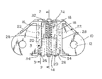
Figure 1 is a top view of a wedge assembly made in
accordance with the teachings of the present invention;

- 2 _
Figure 2 is a view of the wedge assembly 'taken
along lines 2-2 of figure 1; and
Figure 3 is a view of the wedge assembly
taken along lines 3-3 of figure 1.
The wedge assembly has a base plate 10 which
has a pair of holes 12 permitting connection by bolts
or 'the like to the door of a vehicle. The base plate
supports a movable slide element 14 which is
slideable along a pair of spaced parallel and inclined
cam surfaces 16 defined on the base plate. The slide
element is pulled toward its start position, at the
left end of the cam surfaces in figure 2 by a spring
element 18 and can be forced down the cam surfaces
against the action of the spring by the vehicle
surface which it strikes when the door is closed.
The slide element 14 is generally U-shaped
(upside down) with the bottom surfaces 20 comprising
the cam followers. Elongated slots 22 are defined in
the base plate 10 in which stop elements 24 are
located. These stop elements extend downwardly from
flanges 26 that extend horizontally outwardly from the
U-shaped body arid are displaceable within the slots
22. The flanges 26 are trapped by overlying inwardly
extending base plate flanges 28. Movement of the
wedge element to the left (to the start position) is
stopped by engagement of the rear vertical surfaces 30
of the wedge element with inwardly extending base
platy projectories 32 and forward movement is limited
by the engagement of each stop 24 with the portion 34
of the base plate at the forward end of its slot 22.

- 3 -
To permit assembly, the overlying flanges 28
terminate short of the forward of the forward end of
the slots and are beveled 36 inwardly along the lower
front edge. As shown in figure 3, the slide element
can be pivoted into its trapped operating location
(the front portion of the overlying flanges 28 will be
slightly deflected).
As can be seen from figure 2, the ends of the
spring are captured by J-shaped catches 40 which open
in the direction apposite to the removal direction for
the ends of the spring. These J-shaped hooks or
catches minimize the likelihood that the spring can
come off a result of snapping the wedge element.

Representative Drawing
A single figure which represents the drawing illustrating the invention.
Administrative Status

2024-08-01:As part of the Next Generation Patents (NGP) transition, the Canadian Patents Database (CPD) now contains a more detailed Event History, which replicates the Event Log of our new back-office solution.

Please note that "Inactive:" events refers to events no longer in use in our new back-office solution.

For a clearer understanding of the status of the application/patent presented on this page, the site Disclaimer , as well as the definitions for Patent , Event History , Maintenance Fee  and Payment History  should be consulted.

Event History

Description Date
Inactive: IPC from MCD 2006-03-11
Time Limit for Reversal Expired 2004-08-23
Letter Sent 2003-08-22
Letter Sent 2003-02-06
Grant by Issuance 2000-06-20
Inactive: Cover page published 2000-06-19
Pre-grant 2000-03-16
Inactive: Final fee received 2000-03-16
Notice of Allowance is Issued 1999-09-28
Letter Sent 1999-09-28
Inactive: Approved for allowance (AFA) 1999-09-07
Amendment Received - Voluntary Amendment 1999-06-11
Inactive: S.30(2) Rules - Examiner requisition 1998-12-14
Inactive: Delete abandonment 1997-11-12
Deemed Abandoned - Failure to Respond to Maintenance Fee Notice 1997-08-22
Letter Sent 1997-07-18
Inactive: Status info is complete as of Log entry date 1997-07-17
Inactive: Application prosecuted on TS as of Log entry date 1997-07-17
All Requirements for Examination Determined Compliant 1997-04-18
Request for Examination Requirements Determined Compliant 1997-04-18
Application Published (Open to Public Inspection) 1991-04-13

Abandonment History

Abandonment Date Reason Reinstatement Date
1997-08-22

Maintenance Fee

The last payment was received on 1999-08-09

Note : If the full payment has not been received on or before the date indicated, a further fee may be required which may be one of the following

  • the reinstatement fee;
  • the late payment fee; or
  • additional fee to reverse deemed expiry.

Please refer to the CIPO Patent Fees web page to see all current fee amounts.

Fee History

Fee Type Anniversary Year Due Date Paid Date
Request for examination - standard 1997-04-18
MF (application, 7th anniv.) - standard 07 1997-08-22 1997-08-01
MF (application, 8th anniv.) - standard 08 1998-08-24 1998-08-05
MF (application, 9th anniv.) - standard 09 1999-08-23 1999-08-09
Final fee - standard 2000-03-16
MF (patent, 10th anniv.) - standard 2000-08-22 2000-08-02
MF (patent, 11th anniv.) - standard 2001-08-22 2001-08-02
MF (patent, 12th anniv.) - standard 2002-08-22 2002-08-02
Registration of a document 2002-12-18
Owners on Record

Note: Records showing the ownership history in alphabetical order.

Current Owners on Record
BLACK & DECKER, INC.
Past Owners on Record
GARY L. SCHUBRING
THEODORE E. ELWARD
THOMAS A. FLOWERS
Past Owners that do not appear in the "Owners on Record" listing will appear in other documentation within the application.
Documents

To view selected files, please enter reCAPTCHA code :


To view images, click a link in the Document Description column. To download the documents, select one or more checkboxes in the first column and then click the "Download Selected in PDF format (Zip Archive)" or the "Download Selected as Single PDF" button.

List of published and non-published patent-specific documents on the CPD .

If you have any difficulty accessing content, you can call the Client Service Centre at 1-866-997-1936 or send them an e-mail at CIPO Client Service Centre.


Document
Description 
Date
(yyyy-mm-dd) 
Number of pages   Size of Image (KB) 
Cover Page 2000-05-26 1 29
Representative drawing 1999-07-09 1 11
Claims 1999-06-11 1 36
Description 1999-06-11 4 129
Representative drawing 2000-05-26 1 12
Claims 1994-02-05 1 36
Description 1994-02-05 3 98
Cover Page 1994-02-05 1 18
Abstract 1994-02-05 1 10
Drawings 1994-02-05 1 28
Acknowledgement of Request for Examination 1997-07-18 1 178
Commissioner's Notice - Application Found Allowable 1999-09-28 1 163
Maintenance Fee Notice 2003-09-22 1 173
Correspondence 2000-03-16 1 53
Fees 1993-07-15 1 41
Fees 1995-07-28 1 59
Fees 1996-07-22 1 57
Fees 1994-07-29 1 53
Fees 1992-07-16 1 40