Note: Descriptions are shown in the official language in which they were submitted.
2023878
HANDSET
BACKGROUND OF THE INVENTION
ield of the Inventio~:
This invention relates to a handset which is used as
a part of a telephone, such as one installed in an
automobile.
Prior art handsets will be described hereinbelow in
connection with the drawings.
SUMMARY OF THE.INVENTION
Under these circumstances, it is an object of this
invention to provide a handset which can be magnetically
held on the main body of a telephone when hung up, and
detected when hung up or taken off, by a simple combination
of parts including a relatively small magnet.
It is another object of this invention to provide a
handset which is free of any parts that are likely to impose
any substantial restriction on the positioning of a magnetic
detector.
In accordance with one aspect of the invention there
is provided a handset device comprising: a handset held
removably on a main body; a magnet unit provided in one of a
portion of said handset and a portion of said main body
which face each other when said handset is held on said main
.
, ~
. .
202~878
body; a magnetic material provided in the other of said
portions so that a magnetic attracting force may occur
between said magnet unit and said magnetic material, said
magnetic material having a saturation magnetic flux density
which is lower than that of said magnet unit, so that
magnetic leakage may occur past said magnetic material: and
means provided behind said magnetic material in said other
portion for detecting said magnetic leakage.
The device of this invention does not call for the
use of any large magnet, but is simple and compact in
construction, and can, therefore, be manufactured at a low
cost. The magnetic flux leaking from the magnetic material
ensures that the handset be properly held on the main body
when hung up, and that the magnetic detector properly
function to output a corresponding signal.
The area in which the magnet member and the magnetic
material are adapted to face each other is so small that the
handset may have a configuration defined by a variety of
curved lines and planes which play an important role in
raising the ornamental value of the device.
BRIEF ~ESCRIPTION OF THE DRAWINGS
FIGURE 1 is a side elevational view, in section, of
a known handset device;
FIGURE 2 is a partly cutaway side elevational view
of another known handset device;
2023878
FIGURE 3 is an exploded perspective view of a
portion of the device shown in FIGURE 2;
FIGURE 4 is a side elevational view, in section, of
a handset device embodying this invention;
FIGURE 5 is a sectional view taken along the line
V-V of FIGURE 4;
FIGURE 6 is an enlarged exploded perspective view of
a portion of the device shown in FIGURE 4;
FIGURE 7 is an enlarged side elevational view, in
lo section, of the portion shown in FIGURE 6, FIGURES 6 and 7
appear together with FIGURE l;
FIGURES 8(A) and 8(B) are views illustrating the
flow of leaking magnetic flux in the device shown in FIGURES
4 to 7;
FIGURE 9 is an exploded perspective view of the
principal poxtion of a device according to another
embodiment o~ this invention;
FIGURE 10 is a perspective view of the principal
portion of a device according to still another embodiment of
this invention; and
FIGURE 11 is a view similar to FIGURE 10, but
showing a device according to a further embodiment of this
invention.
- . .
.
2023878
A handset is in common use as a telephone receiver.
It is taken off the main body of the telephone to start a
telephone call, and is hung up to end it. The use of the
handset is detected by a mechanical switching system.
A known handset is disclosed in, for example, the
Japanese Patent Application filed by Matsushita Electric
Industrial Co., Ltd. on December 20, 1985 and laid open to
the public under No. 146052/1987 on June 30, 1987 prior to
examination on the merits. It is constructed as shown in
FIGURE 1 of the accompanying drawings, and is removably held
on the main body of a telephone by the combination of
mechanical engagement and magnetic attraction. The main
body 1 of the telephone has a projection 2 and the handset 7
has a hole 3 in which the projection 2 is removably engaged.
The main body 1 is provided with a permanent magnet 4 facing
the handset 7. The handset 7 is provided with a magnetic
flux detector 5 and a magnetic material 6 both facing the
permanent magnet 4. The detector 5 is actuated by detecting
the magnetic flux of the permanent magnet 4 and the
permanent magnet 4 and the magnetic material 6 produce a
magnetic attracting force therebetween.
If the handset 7 is taken off the main body 1, the
magnetic flux detector 5 ceases to detect any magnetic flux
and produces an OFF signal. If the handset 7 is hung up,
the detector 5 detects the magnetic flux of the permanent
~ 4 ~
~, , .
2023878
magnet 4 and produces an ON signal. The magnetic attracting
force occurring between the permanent magnet 4 and the
magnetic material 6, as well as the engagement of the
projection 2 in the hole 3, ensures that the handset 7 be
securely held on th~ main body 1 when hung up.
A switching mechanism including a magnetic catch is
disclosed in the Japanese Utility Model Application filed by
Uniden Co., Ltd. on March 27, 1987 and laid open to the
public under No. 152335/1988 on October 6, 1988 prior to
examination on the merits. This mechanism is employed in an
automobile telephone set as shown in FIGURES 2 and 3.
The telephone set comprises a base unit 40 and a
handset 50. The base unit 40 is provided with a permanent
magnet 11 and two yokes 12, and the handset 50 is provided
with a principal magnetic member 15 facing the yokes 12.
The magnet 11, yokes 12, and magnetic member 15 define a
magnetic catch 10 when the magnetic member 15 is attracted
by the magnet 11. Each yoke 12 has an edge projection 14
provided for holding the magnetic member 15 by magnetic
attraction when the handset 50 is hung up. The edge
projection 14 defines an edge portion 13 which is recessed,
or located apart from the magnetic member 15 when the
handset 50 is hung up. The magnetic member 15 is partly cut
so as not to cover fully the ad;acent edges of the yokes 12,
so that the recessed edge portions 13 of the yokes 12 may
2023878
allow for the leakage of magnetic flux. The hàndset 50 is
further provided with an auxiliary magnetic member 20 and a
magnetically sensitive element 30 which face the recessed
edge portions 13 of the yoXes 12. When the handset 50 is
hung up, the leaking magnetic flux flows along a closed
path F defined by the recessed edge portions 13 of the
yokes 12, the auxiliary magnetic member 20 and the
magnetically sensitive element 30, and the element 30
outputs an ON signal, while it outputs an OFF signal when
lo the handset 50 is not hung up.
In the device as shown in FIGURE 1, however, the
same permanent magnet 4 is used for both detecting the
handset 7 and holding it and the magnetic detector 5 and the
magnetic material 6 are both ~uxtaposed to the magnet 4.
These features make it essential that the magnet 4 be large
enough, and that the device as a whole be correspondingly
large.
In the device as shown in FIGURES 2 and 3, it is
necessary to use a sufficiently long permanent magnet 11 or
arrange the relevant parts in a mutually displaced way in
order to ensure the leakage of magnetic flux from the magnet
11, while the auxiliary magnetic member 20 is essential for
preventing the scattering of the leaking magnetic flux.
Therefore, the device necessarily is large and comprises a
large number of parts forming a complicated arrangement.
2023878
A small size, as well as a high level of
performance, is now required of a handset. Moreover, the
user is inclined from a standpoint of human engineering to
choose a device having a shape defined by many curved lines
and planes. While a handset and the main body of a
telephone, or a stand on which the handset is placed become
smaller, they are, on the contrary, required to contain a
greater number of parts to achieve a higher level of
performance.
Therefore, a more compact and simpler construction
is required of those portions at which the handset is held
on the main body of the telephone when hung up. This
requirement is also essential to enable the realization of a
configuration define by many curved planes. Moreover, the
use of a greater number of parts imposes more restrictions
on the p~ssible arrangement of those parts in the limited
space defined by the handset or the main body of the
telephone and thereby on the possible shape of the handset
or the main body of the telephone.
The device as shown in FIGURE 1 cannot, however, be
constructed with a satisfactorily curved configuration, as
it calls for a permanent magnet having a large flat surface
area. The device as shown in FIGURES 2 and 3 has already a
greatly limited inner space due to the presence of the
auxiliary magnetic member and other parts associated
therewith.
The invention will now be described in detail with
,
2~23878
reference to the accompanying drawings showing a few
preferred embodiments thereof.
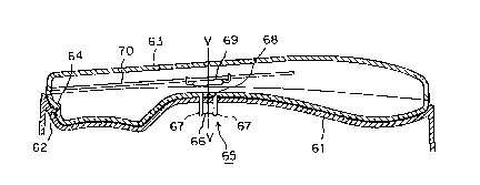
Referring first to FIGURE 4, a handset device
embodying this invention comprises a main body 61 provided
with a projection 62 on its wall, and a handset 63 provided
in its wall with a depression 64 in which the projection
62 is engageable as shown. A magnet unit 65 is provided
in a portion of the main body 61 facing the handset 63 in
its hung-up position. The magnet unit 65 comprises a
permanent magnet 66 and a pair of yokes 67 provided on the
opposite pole faces, respectively, of the magnet 66. Each
yoke 67 has an edge projection 67a as shown in FIGURE 6 or
7 and the wall of the main body 61 has a pair of slots 61a
in which the edge projections 67a of the yokes 67 are res-
pectively fitted, as shown in FIGURE 7, whereby the magnet
unit 65 is secured to the main body 61.
The handset 63 is provided with a magnetic material
68 adapted to face the edges of the yokes 67 when the hand-
set 63 is hung up, so that a magnetic attracting force may
occur between the yokes 67 and the magnetic material 68.
The magnetic material 68 has a saturation magnetic flux
density which is lower than that of the yokes 67, 90 that
magnetic flux may leak from the magnetic material 68. A
magnetic detector 69 is provided behind the magnetic mate-
rial 68 and is supported on a printed-circuit board 70 in
~ .
, . -
2 ~
the hrndset 63, as shown in FIGURES 4 and 5. The magnetic
detector 69 comprises, for example, a lead relay and is
operable by detecting the magnetic flux leaking from the
magnetic material 68.
When the handset 63 is off the main body 61, the
magnet.ic detector 69 outputs an OFF signal, as it does not
detect any magnetic flux. This is the situation which
corresponds to the off-hook position of a telephone.
If the handset 63 is hung up on the main body 61
as shown in FIGURE 4, the yokes 67 and the magnetic mate- .
rial 68 attract each other, while the projection 62 is en-
gaged in the depression 64, so that the handset 63 is held
securely on the main body 61.
The yokes 67 are so formed as to have an equal
saturation magnetic flux density, and an equal thickness
a which depends on the saturation magnetic flux density of
the permanent magnet 66. The yokes 67 and the magnetic
material 68 may be of the same material, and if such is the
case, the magnetic material 68 has a thickness b which is
smaller than the thickness a of the yokes 67, as shown in
FIGURE 6, so that the magnetic material 68 may have a satu-
ration magnetic flux density which is lower than that of
the yokes 67, and may a.llow magnetic flux to leak from the
yokes 67 and form a magnetic loop passing behind the mag-
netic material 68. The magnetic detector 69 is situated
.. . .
~` :
202387~
in the magnetic loop and outputs an ON signal when the
handset 63 is hung up. This is the situation which corres-
ponds to the on-hook position of the telephone.
Reference is now made to FIGURES 8(A) and 8(B)
showing the mechanism which causes the leakage of magnetic
flux. The following relationships are first considered
to exist:
~M = SM x BM;
Bi = ~ x BM;
Bi' = ~ = ~T x BM,
where BM is the saturation magnetic flux density of the
permanent magnet 66, Bi is the saturation magnetic flux
density of the yokes 67, Bi.' is the saturation magnetic
flux density of the magnetic material 68, SM is the area
of the contacting surfaces of the permanent magnet 66 and
the yokes 67, Si is the cross-sectional area of the yokes
67, Sl' is the cross-sectional area of the magnetic mate-
rial 68, and ~M is the strength of a magnetic field.
If Si is larger than Si', no magnetic leakage occurs
unless Bi is lower than Bi', and if Bi is equal to Bi', no
magnetic leakage occurs unless Si is equal to Si'.
If Si' is equal to a half of Si, and if the yokes
67 and the magnetic material 68 are of the same material,
the leaking magnetic flux, ~M', is defined as:
~M' = Bi x (Si-Si') = Bi x Si = _ x BiSi
-- 10 --
' ' .
.,......................... ::
, .;.
-` 2~23g78
It will be noted from the e~uation that the amount of
magnetic leakage is proportional to a reduction in cross-
sectional area of the magnetic material 68. Therefore,
it is possible to obtain a different amount of magnetic
leakage lf the ratio in thickness of the magnetic material
68 to the yokes 67 is altered.
Although the magnetic detector 69 has been described
as comprising a lead relay, it may alternatively comprise
a ho'e device, or anything else that is appropriate. Al-
though the permanent magnet 66 has been described as being
provided in the main body 61, and the magnetic material 68
and the magnetic detector 69 in the handset 63, it is pos-
sible to reverse the arrangement of those parts. Although
the different saturation magnetic flux densities of the
yokes 67 and the magnetic material 68 have been described
as being achieved by their difference in thickness, the
same can also be realized by employing different materials,
for example, Permalloy and mild steel.
A different embodiment of this invention is shown
in FIGURE 9. It i9 characterized by including a magnetic
material 68 having a portion with a thickness b which is
smaller than the thickness a of the yokes 67, while thè
remaining portions thereof are e~ual in thickness to the
yokes 67. Accordingly, it is only in that portion of
smaller thickness that magnetic leakage occurs.
.
.
2~23~78
Two modified forms of the device shown in FIGURE
9 are shown by way of example in FIGURES 10 and 11, res-
pectively. The device shown in EIGURE 10 includes a
magnetic material consisting of two flat plates 68a and
68b having different saturation magnetic flux densities
and joined together to form a single plate. The device
shown in FIGURE 11 includes a magnetic material consisting
of a flat plate 68a and a flat plate 68b having a depression
or opening 71 and laid on, and bonded to, the plate 68a.
- 12 -
-
.