Language selection

Search

Patent 2023911 Summary

Third-party information liability

Some of the information on this Web page has been provided by external sources. The Government of Canada is not responsible for the accuracy, reliability or currency of the information supplied by external sources. Users wishing to rely upon this information should consult directly with the source of the information. Content provided by external sources is not subject to official languages, privacy and accessibility requirements.

Claims and Abstract availability

Any discrepancies in the text and image of the Claims and Abstract are due to differing posting times. Text of the Claims and Abstract are posted:

  • At the time the application is open to public inspection;
  • At the time of issue of the patent (grant).
(12) Patent: (11) CA 2023911
(54) English Title: PROCEDURE AND APPARATUS FOR THE PURIFICATION OF AIR, FLUE GASES OR EQUIVALENT
(54) French Title: METHODE ET APPAREIL DE PURIFICATION D'AIR, DE GAZ DE COMBUSTION OU AUTRES GAZ EQUIVALENTS
Status: Term Expired - Post Grant Beyond Limit
Bibliographic Data
(51) International Patent Classification (IPC):
  • B3C 3/08 (2006.01)
  • B3C 3/12 (2006.01)
  • B3C 3/15 (2006.01)
  • B3C 3/36 (2006.01)
  • B3C 3/38 (2006.01)
  • B3C 3/68 (2006.01)
  • B3C 3/72 (2006.01)
  • B3C 3/78 (2006.01)
(72) Inventors :
  • ILMASTI, VEIKKO (Finland)
(73) Owners :
  • ION BLAST LTD.
  • OY AIRTUNNEL LTD
(71) Applicants :
  • ION BLAST LTD. (Finland)
  • OY AIRTUNNEL LTD (Finland)
(74) Agent: CASSAN MACLEAN
(74) Associate agent:
(45) Issued: 2004-11-16
(22) Filed Date: 1990-08-23
(41) Open to Public Inspection: 1991-02-26
Examination requested: 1990-12-28
Availability of licence: N/A
Dedicated to the Public: N/A
(25) Language of filing: English

Patent Cooperation Treaty (PCT): No

(30) Application Priority Data:
Application No. Country/Territory Date
893998 (Finland) 1989-08-25

Abstracts

English Abstract


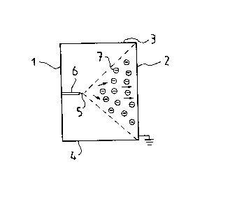
Procedure and apparatus for the
purification of air, flue gases or equivalent, in
which procedure the air, flue gases or
equivalent are directed into a duct or
equivalent, in which procedure the air,
flue gases or equivalent are ionized, and
in which procedure the charged impurity
particles (7) present in the air, flue
gases or equivalent are attracted by one
or more collector surfaces (2) by virtue
of a difference in the states of charge,
causing the particles to settle on said
surface. The air, flue gases or
equivalent are ionized by means of one or more
ionizing electrodes (5) directed at a
collector surface. The distance between
the ionizing electrode,or equivalent and
the collector surface as well as the
difference between the states of electric
charge of the collector surface and the
charged impurity particles are so
adjusted that the impurity particles will
be carried by an ion beam essentially
directly towards the collector surface and
settle on it.


Claims

Note: Claims are shown in the official language in which they were submitted.


30
WHAT IS CLAIMED IS:
1. An apparatus for purification of gases, comprising:
a duct for receiving gases flowing therethrough,
said duct including a collector surface on an interior wall portion of said
duct,
an emitter means, mounted on another interior wall portion of said duct at a
distance in the range of 100-1000 mm from said collector surface, for creating
an ion jet toward said collector surface,
said emitter means, including a thin metal wire, one end of which is directed
toward said collector surface, and said ion jet commencing from that end in a
substantially conical shape toward said collector surface,
the distance and relative electric charge between said collector surface and
said
emitter means being established such that impurities of the size range from
smaller than 0.005 pm to 0.1 Nm and up present in the gases flowing through
said duct are carried at substantially a right angle toward and settle on said
collector surface by said ion jet at a collection efficiency which remains
high for
all of the said impurity size ranges,
said collector surface extending for less than the entire cross-sectional
perimeter
of said duct,
wherein a sufficiently high voltage of 100 KV or more is applied to said
emitter
means so as to cause ion impact upon said impurities to cause said impurities
to move in the direction of said collector surface, in addition to causing
electrical
attraction of said impurities to said collector surface so as to retain said
impurities on said collector surface,
and means for producing a high voltage supply of power to said emitter means
and a supervision unit which is electrically connected to the means for
supplying
that power in order to interrupt the supply of power when any of the humidity,
temperature or current to the ionizing electrode is out of a predetermined
range.

Description

Note: Descriptions are shown in the official language in which they were submitted.


2~23~11
1
The present invention concerns a method and an apparatus for
the purification of air, flue gases or the like, in which
procedure the air, flue gases are directed into a duct, in
which method the air, flue gases are ionized and charged
impurity particles present in the air, flue gases are attracted
by collector surfaces by virtue of a difference in the states
of charge, causing the particles to settle on said surface(s),
and in which method the air, flue gases is ionized by means of
one or more ionizing electrodes directed towards the collector
surface.
GB-patent publication 1 238 438 proposes a method and an
apparatus for the removal of dust particles from the air in a
tunnel. In the method presented in the publication mentioned,
the tunnel is provided with electrodes, to which a high voltage
is applied. The electrodes charge the particles in the air in
the tunnel by producing an electric field between the interior
wall of the tunnel and the electrodes. Thus the charged dust
particles are attracted to the interior walls of the tunnel.
For the air to be sufficiently purified, it has to be very
strongly ionized in order that all particles in the tunnel
should be charged and settle when they encounter an interior
surface of the tunnel. Moreover, several electrodes and a long
tunnel are needed. SE-application publication 8501858-8
proposes a procedure for eliminating or reducing the emissions
of SOx and NOx.
DE-C-526.021 refers to a centrifugal electofilter which is a
combination of a normal ionizing apparatus and a centrifugal
device. Particles transported with the flow of air become
ionized in the duct, whereupon the centrifugal force cause the
particles to be displaced towards the outer duct wall. The
particles are displaced only in the direction of the
centrifugal force. The ionization gives the particles a
retaining force, whereby the particles adhere to the duct wall,
when they have already been moved there by the centrifugal
force. This gives a much higher energy consumption and limits
D

2~23~i1
1A
the applicability of the process and device.
The object of the present invention is to eliminate the
drawbacks of the previously known techniques. The method of
the invention for the purification of air, flue gases or
equivalent is characterized in that the voltage applied to the
ionizing electrode (5) is in the order of 100 - 250 kV whereby
a conical ion beam is produced and in that the distance between
the ionizing electrode or equivalent and the collector surface
as well as the difference between the states of electric charge
of the collector surface and the charged impurity particles are
so adjusted that the impurity particles will be carried only
by said conical ion beam essentially directly towards the
collector surface and settle on it.
The preferred embodiments of the invention are presented in the
other claims.
The invention provides the following advantages over current
methods:
Efficient purification even in a short duct. Considerable
reduction in energy consumption as compared to current
procedures. The need for maintenance is reduced as the
collector surfaces can be washed simply with a water jet.
Air can be purified regarding different particle sizes down to
pure gases. The invention makes it possible to remove
particles as small as 0.005 ~m and even smaller.
In the following, the invention is described in greater detail
by the aid of examples with reference to the drawings attached,
in which
Fig. 1 illustrates air purification in a duct by the procedure
of the invention.
v

2~239i1
2
Fig. 2 also illustrates air purification in a corridor or duct
by the procedure of the invention.
Fig. 3 illustrates the cleaning of a wall acting as a collector
surface.
Fig. 4 shows a tube used for air purification.

~~2391i
Fig. 5 shows an expanded tube used for air purification.
Fig. 6 shows a spiral tube.
Fig. 7 shows a voltage supply unit.
Fig. 8 shows a structure for air intake and air outlet.
Fig. 1 presents a duct which has side walls 1 and 2, a
ceiling 3 and a floor 4. The fresh air supplied into a
building or the air to be re-circulated is directed into
the duct for removal of impurity particles. For purifica-
tion, the air is ionized by means of an ionizing electrode
S mounted on a bracket 6 and connected with a cable to a
voltage supply unit, which will be described later. The
ionizing electrode 5 is directed at the opposite side wall
2, which is earthed and acts as a particle-collecting
surface. The voltage applied to the ionizing electrode 5,
which is of the order of 100 - 250 k~, and the distance
between the ionizing .electrode and the side wall are so
adjusted that a conical ion beam or ion jet as indicated by
the broken lines is produced. With this arrangement, the
(negatively) charged impurity particles 7 will move direct-
ly to the side wall 2 and settle on it due to the differ-
ence in electric charge between the particles and the wall.
The ion jet can be felt near the wall as a cool ion cur-
rent. The distance between the ionizing electrode and the
collecting wall is typically 100 - 1000 mm.
Fig. 2 shows a top view of a duct with earthed side walls 8
and 9 and two ionizing electrodes 10 and 11 mounted on
brackets 12 and 13. This arrangement allows a more effi-
cient purification of the air as the first electrode 10
produces a conical ion beam causing impurity particles 14
to move towards wall 8 and settle on it while the second
electrode 11 produces an ion beam causing impurity par-
ticles 15 to move to the opposite wall 9, so that the air
is efficiently purified over the whole sectional area of
the duct.

4 ~~2~~~1
Fig. 3 illustrates the cleaning of the collector surface 2
using a water jet. The water is sprayed onto the surface
through a nozzle 16, to which it is supplied via a hose 17
from a container 18. The duct floor 19 is V-shaped, so that
the water is gathered in the middle of the floor, from
where it can be directed further e.g. into a drain.
Fig. 4 shows a tubular purification duct 20 with ionizing
electrodes 21. The duct has a curved shape such that the
cleaning water will flow out through an exit opening 22 as
indicated by the arrows.
Fig. 5 shows a tubular purification duct 22 provided with
an expansion 23 to retard the flow of air through it, the
walls of the expanded part acting as collecting surfaces.
The expanded part is provided with ionizing electrodes 24
and 25 mounted on brackets 26 and 27 on opposite walls. The
impurity particles 28 and 29 drift towards the collecting
surfaces as explained above. Fig. 6 presents a spiral tube
30 with ionizing electrodes 31 and 32 mounted on brackets
33 and 34. The impurity particles settle on the earthed
wall of the tube 30. The water used for cleaning the spiral
tube exits through the lower end as indicated by the arrows.
Fig. 7 shows a diagram of the power supply unit, which sup-
plies a voltage to the ionizing electrodes. The unit com-
prises high-voltage and low-voltage units 37 and 38, which
are fed by the mains voltage Vln, e.g. 220 V. The
high-voltage and low-voltage units control a pulse-width
modulator 39. The output of the pulse-width modulator is
connected to the primary side of a high-voltage
transformer 40, and the transformer output is connected to
a high-voltage cascade 41, whose output voltage Vout is
applied to the ionizing electrodes. The mains voltage also
feeds the power supply 43 of a microprocessor 42.
Connected to the microprocessor are sensors for the
ionizing current, duct temperature and humidity and for a

2~2~911
solenoid controlling the spraying of wash water through the
nozzle. The sensors give an alarm in the form of a signal
light in an alarm unit 44 and also an inhibit signal to the
modulator, preventing the supply of voltage. The output
voltage Vo~t is adjusted by means of a regulating element 45.
Fig. 8 presents a tubular duct 37a for intake air, provided
with an ionizing electrode 38a in the manner described above.
The purification duct 37a is surrounded by an exit air duct
39a, so that the action of the structure resembles that of a
heat exchanger.
It is obvious to a person skilled in the art that different
embodiments of the invention are not restricted to the examples
described above, but that they may instead be varied within the
scope of the following claims. Instead of earthed collector
surfaces, it is also possible to use collector surfaces having
a charge of opposite sign in relation to the ions.
.~

Representative Drawing
A single figure which represents the drawing illustrating the invention.
Administrative Status

2024-08-01:As part of the Next Generation Patents (NGP) transition, the Canadian Patents Database (CPD) now contains a more detailed Event History, which replicates the Event Log of our new back-office solution.

Please note that "Inactive:" events refers to events no longer in use in our new back-office solution.

For a clearer understanding of the status of the application/patent presented on this page, the site Disclaimer , as well as the definitions for Patent , Event History , Maintenance Fee  and Payment History  should be consulted.

Event History

Description Date
Inactive: Expired (new Act pat) 2010-08-23
Inactive: Late MF processed 2010-02-04
Letter Sent 2009-08-24
Inactive: Late MF processed 2008-03-19
Letter Sent 2007-08-23
Inactive: Late MF processed 2007-08-23
Letter Sent 2006-08-23
Inactive: IPC from MCD 2006-03-11
Grant by Issuance 2004-11-16
Inactive: Cover page published 2004-11-15
Pre-grant 2004-08-26
Inactive: Final fee received 2004-08-26
4 2004-03-11
Letter Sent 2004-03-11
Notice of Allowance is Issued 2004-03-11
Inactive: Approved for allowance (AFA) 2004-03-02
Letter Sent 2004-02-24
Inactive: Single transfer 2004-01-16
Amendment Received - Voluntary Amendment 2004-01-15
Inactive: Delete abandonment 2003-10-02
Inactive: Office letter 2003-10-02
Inactive: Entity size changed 2003-08-28
Deemed Abandoned - Failure to Respond to Maintenance Fee Notice 2003-08-25
Inactive: S.30(2) Rules - Examiner requisition 2003-07-15
Inactive: Office letter 2002-11-19
Letter Sent 2002-11-14
Inactive: Reversal of dead status 2002-10-29
Inactive: Delete abandonment 2002-10-29
Inactive: Correspondence - Prosecution 2002-10-10
Reinstatement Request Received 2002-09-20
Letter Sent 2002-09-19
Reinstatement Requirements Deemed Compliant for All Abandonment Reasons 2001-10-04
Inactive: Dead - No reply to s.30(2) Rules requisition 2001-10-04
Inactive: Office letter 2001-07-25
Reinstatement Requirements Deemed Compliant for All Abandonment Reasons 2001-06-20
Inactive: Abandoned - No reply to s.30(2) Rules requisition 2000-10-04
Deemed Abandoned - Failure to Respond to Maintenance Fee Notice 2000-08-23
Inactive: S.30(2) Rules - Examiner requisition 2000-04-04
Inactive: Adhoc Request Documented 2000-04-04
Inactive: S.30(2) Rules - Examiner requisition 2000-04-04
Amendment Received - Voluntary Amendment 1999-12-16
Letter Sent 1999-11-19
Reinstatement Request Received 1999-10-18
Reinstatement Requirements Deemed Compliant for All Abandonment Reasons 1999-10-18
Inactive: Abandoned - No reply to s.30(2) Rules requisition 1998-10-19
Letter Sent 1998-10-06
Reinstatement Requirements Deemed Compliant for All Abandonment Reasons 1998-09-23
Letter Sent 1998-09-08
Deemed Abandoned - Failure to Respond to Maintenance Fee Notice 1998-08-24
Letter Sent 1998-06-03
Inactive: First IPC assigned 1998-05-12
Inactive: IPC removed 1998-05-12
Inactive: IPC assigned 1998-05-12
Inactive: S.30(2) Rules - Examiner requisition 1998-04-17
Inactive: Correspondence - Prosecution 1998-03-19
Withdraw from Allowance 1998-02-23
Inactive: Office letter 1998-02-23
Inactive: Final fee received 1998-01-07
Notice of Allowance is Issued 1997-07-28
Letter Sent 1997-07-28
4 1997-07-28
Notice of Allowance is Issued 1997-07-28
Inactive: Status info is complete as of Log entry date 1997-07-24
Inactive: Application prosecuted on TS as of Log entry date 1997-07-24
Inactive: First IPC assigned 1997-07-22
Inactive: IPC assigned 1997-07-22
Inactive: IPC removed 1997-07-22
Inactive: IPC assigned 1997-07-22
Inactive: IPC removed 1997-07-22
Inactive: IPC assigned 1997-07-22
Inactive: IPC removed 1997-07-22
Inactive: IPC assigned 1997-07-22
Inactive: Approved for allowance (AFA) 1997-07-21
Application Published (Open to Public Inspection) 1991-02-26
Request for Examination Requirements Determined Compliant 1990-12-28
All Requirements for Examination Determined Compliant 1990-12-28

Abandonment History

Abandonment Date Reason Reinstatement Date
2003-08-25
2002-09-20
2000-08-23
1999-10-18
1998-08-24

Maintenance Fee

The last payment was received on 2004-08-17

Note : If the full payment has not been received on or before the date indicated, a further fee may be required which may be one of the following

  • the reinstatement fee;
  • the late payment fee; or
  • additional fee to reverse deemed expiry.

Patent fees are adjusted on the 1st of January every year. The amounts above are the current amounts if received by December 31 of the current year.
Please refer to the CIPO Patent Fees web page to see all current fee amounts.

Fee History

Fee Type Anniversary Year Due Date Paid Date
MF (application, 7th anniv.) - small 07 1997-08-25 1997-08-21
MF (application, 8th anniv.) - small 08 1998-08-24 1998-08-10
Reinstatement 1998-09-23
MF (application, 9th anniv.) - small 09 1999-08-23 1999-08-18
Reinstatement 1999-10-18
MF (application, 11th anniv.) - small 11 2001-08-23 2001-06-20
Reinstatement 2001-06-20
MF (application, 10th anniv.) - small 10 2000-08-23 2001-06-20
Reinstatement 2001-10-04
MF (application, 12th anniv.) - standard 12 2002-08-23 2002-08-13
MF (application, 13th anniv.) - standard 13 2003-08-25 2003-08-13
Registration of a document 2004-01-16
MF (application, 14th anniv.) - standard 14 2004-08-23 2004-08-17
Final fee - standard 2004-08-26
MF (patent, 15th anniv.) - standard 2005-08-23 2005-08-09
MF (patent, 16th anniv.) - standard 2006-08-23 2007-08-23
Reversal of deemed expiry 2009-08-24 2007-08-23
Reversal of deemed expiry 2009-08-24 2008-03-19
MF (patent, 17th anniv.) - standard 2007-08-23 2008-03-19
MF (patent, 18th anniv.) - standard 2008-08-25 2008-08-13
Reversal of deemed expiry 2009-08-24 2010-02-04
MF (patent, 19th anniv.) - standard 2009-08-24 2010-02-04
Owners on Record

Note: Records showing the ownership history in alphabetical order.

Current Owners on Record
ION BLAST LTD.
OY AIRTUNNEL LTD
Past Owners on Record
VEIKKO ILMASTI
Past Owners that do not appear in the "Owners on Record" listing will appear in other documentation within the application.
Documents

To view selected files, please enter reCAPTCHA code :


To view images, click a link in the Document Description column (Temporarily unavailable). To download the documents, select one or more checkboxes in the first column and then click the "Download Selected in PDF format (Zip Archive)" or the "Download Selected as Single PDF" button.

List of published and non-published patent-specific documents on the CPD .

If you have any difficulty accessing content, you can call the Client Service Centre at 1-866-997-1936 or send them an e-mail at CIPO Client Service Centre.


Document
Description 
Date
(yyyy-mm-dd) 
Number of pages   Size of Image (KB) 
Representative drawing 2003-09-23 1 3
Drawings 1993-12-12 4 49
Cover Page 1993-12-12 1 13
Description 1993-12-12 5 177
Abstract 1993-12-12 1 23
Claims 1993-12-12 3 78
Description 1997-04-29 6 215
Claims 1997-04-29 2 67
Drawings 1997-04-29 4 50
Claims 2004-01-14 1 41
Representative drawing 2001-05-21 1 3
Claims 2001-10-03 3 109
Cover Page 2004-10-17 1 39
Commissioner's Notice - Application Found Allowable 1997-07-27 1 164
Courtesy - Abandonment Letter (Maintenance Fee) 1998-09-20 1 184
Notice of Reinstatement 1998-10-05 1 170
Courtesy - Abandonment Letter (R30(2)) 1998-12-20 1 170
Notice of Reinstatement 1999-11-18 1 173
Courtesy - Abandonment Letter (Maintenance Fee) 2000-09-19 1 184
Notice of Reinstatement 2002-11-13 1 171
Courtesy - Abandonment Letter (R30(2)) 2002-11-12 1 168
Courtesy - Certificate of registration (related document(s)) 2004-02-23 1 107
Commissioner's Notice - Application Found Allowable 2004-03-10 1 161
Maintenance Fee Notice 2006-10-17 1 173
Maintenance Fee Notice 2007-10-03 1 173
Late Payment Acknowledgement 2007-09-10 1 166
Late Payment Acknowledgement 2008-04-09 1 165
Maintenance Fee Notice 2009-10-04 1 170
Late Payment Acknowledgement 2010-02-22 1 164
Correspondence 2002-11-11 1 38
Correspondence 2003-10-01 2 17
Correspondence 1997-07-27 16 749
Correspondence 2002-11-18 1 11
Correspondence 1998-09-07 1 17
Correspondence 1998-02-22 1 7
Correspondence 1998-01-06 1 40
Correspondence 1998-03-12 1 20
Correspondence 2002-09-18 1 31
Fees 2001-06-19 2 67
Fees 1998-09-20 2 168
Correspondence 2004-08-25 1 32
Fees 2007-08-22 1 51
Fees 2008-03-18 1 46
Fees 2010-02-03 1 39
Fees 1996-07-31 1 31
Fees 1995-08-17 1 33
Fees 1994-08-10 1 33
Fees 1993-08-15 1 28
Fees 1992-08-05 1 26