Language selection

Search

Patent 2024474 Summary

Third-party information liability

Some of the information on this Web page has been provided by external sources. The Government of Canada is not responsible for the accuracy, reliability or currency of the information supplied by external sources. Users wishing to rely upon this information should consult directly with the source of the information. Content provided by external sources is not subject to official languages, privacy and accessibility requirements.

Claims and Abstract availability

Any discrepancies in the text and image of the Claims and Abstract are due to differing posting times. Text of the Claims and Abstract are posted:

  • At the time the application is open to public inspection;
  • At the time of issue of the patent (grant).
(12) Patent Application: (11) CA 2024474
(54) English Title: RACKET HEAD WITH INNER PERIPHERAL INDENTATIONS
(54) French Title: CADRE DE RAQUETTE AVEC ENTAILLES SUR LE POURTOUR INTERIEUR
Status: Deemed Abandoned and Beyond the Period of Reinstatement - Pending Response to Notice of Disregarded Communication
Bibliographic Data
(51) International Patent Classification (IPC):
  • A63B 49/02 (2015.01)
  • A63B 49/14 (2015.01)
(72) Inventors :
  • LO, KUN-NAN (Taiwan, Province of China)
  • LO, KUN-NAN (Taiwan, Province of China)
(73) Owners :
  • KUN-NAN LO
  • KUN-NAN LO
(71) Applicants :
(74) Agent: OSLER, HOSKIN & HARCOURT LLP
(74) Associate agent:
(45) Issued:
(22) Filed Date: 1990-08-31
(41) Open to Public Inspection: 1992-03-01
Examination requested: 1992-08-07
Availability of licence: N/A
Dedicated to the Public: N/A
(25) Language of filing: English

Patent Cooperation Treaty (PCT): No

(30) Application Priority Data: None

Abstracts

English Abstract


ABSTRACT OF THE DISCLOSURE
A looped racket frame has two frame portions which
are symmetrically opposite with respect to the
longitudinal axis of the frame to hold some transverse
string lines passing through a central area of the
string web. These opposite frame portions are provided
with two elongated indentations at the inner
peripheries thereof to enlarge the distance between the
string holes which hold the transverse string lines,
thereby lengthening the string lines passing through
the central area.


Claims

Note: Claims are shown in the official language in which they were submitted.

THE EMBODIMENTS OF THE INVENTION IN WHICH AN EXCLUSIVE
PROPERTY OR PRIVILEGE IS CLAIMED ARE DEFINED AS FOLLOWS:
1. A racket frame comprising:
a looped head having an inner periphery, an
opposite outer periphery, a plurality of string holes
extending from said inner periphery to said outer
periphery, and a string web held by said looped head
and having longitudinal and transverse string lines
passing through said string holes,
said looped head having two frame portions which
are symmetrically opposite with respect to a longitudinal
axis of the looped frame, said frame portions holding
some of said transverse string lines which pass through
a central area of said string web, and
two elongated indentations respectively provided in
said frame portions at said inner periphery, said
elongated indentations providing an added distance
between some of said string holes through which said
some of said transverse string lines pass, thereby
elongating said some of said transverse string lines.
2. A racket frame as claimed in Claim 1, wherein each
of said frame portions has two reinforcing ridges on
two sides of said indentation of each of said frame
portions.

Description

Note: Descriptions are shown in the official language in which they were submitted.


2~3~7 ~
This lnvention relates to a racket frame, and
particularly to a looped head of the racket with
two symmetrically opposite inner peripheral
indentations with respect to the longitudinal axis of
the looped frame.
A conventional looped racket frame generally
has an outer grooved peripheral face extending along
the length of the looped head and a substantially
convexed opposite inner peripheral face, wherein the
string lines of the racket run to and fro passing
through -the string holes from the inner peripheral face
to the outer grooved peripheral face which provides a
channel to guide the string to turn inward. The looped
frame is generally oval-shaped which has a
longitudinal axis and a transverse axis.
Generally, the direction of a ball stroke by a
racket depends of the characteristics of the string
web and the point on the string web where the ball
strikes. The angle of deflection of individual string
lines relative to the plane of the string web formed
upon striking the ball is one of the important
characteristics of the string web. The deflection
angles of the string lines are not i~entical since the
lengths of the string lines are different depen~ing on
their positions in the looped frame.
.

3,~ t'~
In vie~ of the above facts, a general conclusion
can be made such that the longer in the string line
is the smaller in the deflection angle of the ball.
As a matter of fact, the direction of a ball is
not merely affected by a deflected single line out by
several deflected string lines including longitudinal
and transverse lines. Therefore, the direction of the
ball depends on the total effect of the strings
impacted by the ball, which renders the direction of
the ball difficult to predict. In order to easily
control the ball, it is desirable to minimize the
deflection angles of the ball imparted by the string
web. To this end, it is necessary to lengthen the
strings.
An object of the invention is to provide a racket
frame with an improvement which permits some transverse
string lines passing through the central striking area
of the racket to be lengthen without altering the
original size of the racket head so that the deflection
at the central striking area of the racket head is
minimized.
,

g' l~
This and other objects can be achieved by the
provision of a looped racket head which has two
elongated indentations respectively provided in the
inner peripheries of two frame portions which are
symmetrically opposite with respect to the
longitudinal axis of the head. ~he opposite frame
portions hol~ some of transverse string lines passing
through a central area of the string web of the head
which is an effective striking area of a racket. The
elongated inner grooves provide added distance between
the opposite frame portions and effectively lengthen
some of the transverse string lines.
In the accompanying drawings:
Figure~ l to S show a conventional racket and the
deflections of the strings when impacted by a ball;
Figure 6 is an elevation view of a looped racket
head incorporating the present invention;
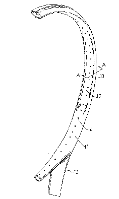
Figure 7 is a perspective view of a portion of the
racket head of Figure 6;
Figure a is a sectional view taken along line A-A
of Figure 7; and
~5 Figure 9 compares the string lines of the present
invention with those of the prior art.
- .

Figures l to 5
show the deflection angles of different string lines
when a ball strikes at Pl, P2, P3 and P4 on the string
web.
When the ~all impacts at the point Pl, the
center of symmetry of the looped frame, the ball will
generally be rebounded in a direction perpendicular to
the string web without deviation. This point is the
best point that permits the player to best predict the
direction of the ball. When the ball impacts points
other than the point Pl, the directions of the rebound
becomes dif~icult to predict. This is because the the
striking points bisect both the longitudinal and
transverse strings into segments of unequal length and
thus will cause different deflection angles of the
strings with respect to the string web. The different
deflections of the two string portions on two sides of
the point cause the rebound ball to uncontrollably
deflect from the vertical line with respect to the
string web.
Referring to Figures 2 and 3 in combination with
Figure 1, the impact points P2 and P3 are on
different longitudinal lines AA and BB but on the same
transverse line CC. The line B3 is longer than the
line AA and thus the line BP3 is longer than the line
AP2. Therefore, the deflection angle ~2' of the longer
line BP3 is smaller than the angle ~l' of the shorter
line AP2. As a result, the deflection angle ~2 of the
ball rebounded from the longer string BB is smaller
' : .. ,~,

~ ~3, 2 ~
than the angle ~1 of the ball rebounded from the
shorter string AA. Similarly, Figl~res 4 and 5 shows
different angles of deflection of the ~alls occl~rring
at points P2 and P4 on a shorter transverse lines CC
and a longer transverse line DD.
- :

Referring to Figures 6 to 8, a racket 10 has a
substantially oval~shaped racket head 11. .~ string
web 20 is attached to the head frame 11 through string
holes 14 bored from the inner periphery to the outer
periphery of tne frame. The outer periphery of the
frame 11 has a peripheral groove 14 extending
substantially the full length of the looped frame 11.
The inner periphery of the head 11 has two elongated
indentations 12 in two frame portions 15 which are
symmetrically opposite with respect to the longitudinal
axis of the head. The frame portions 15 hold some
transverse string lines 16 which pass through a central
area of the string web 20. Reinforcing ridges 13 are
formed on either side of each elongated indentation 12.
Referring to Figure 9, it can be appreciated that
line EE, i.e. the distance between two opposite string
holes at points E, E in the frame portions 15, is
longer than line FF which is the distance bet~een two
opposite string holes in a racket head without the
indentations 12 of the present invention. That is to
say, the strings 16 are lengthened because of the
in~entations 12. The longer string lines 16 minimize
the deflection angle of the ball which hits the central
area of the racket head, therè~y enabling the user to
predict the direction of the ball more easily than with
a conventional racket of the same size.
: : '
.:

Representative Drawing
A single figure which represents the drawing illustrating the invention.
Administrative Status

2024-08-01:As part of the Next Generation Patents (NGP) transition, the Canadian Patents Database (CPD) now contains a more detailed Event History, which replicates the Event Log of our new back-office solution.

Please note that "Inactive:" events refers to events no longer in use in our new back-office solution.

For a clearer understanding of the status of the application/patent presented on this page, the site Disclaimer , as well as the definitions for Patent , Event History , Maintenance Fee  and Payment History  should be consulted.

Event History

Description Date
Inactive: IPC deactivated 2015-03-14
Inactive: IPC from PCS 2015-01-17
Inactive: First IPC from PCS 2015-01-17
Inactive: IPC from PCS 2015-01-17
Inactive: IPC expired 2015-01-01
Inactive: Agents merged 2013-10-23
Application Not Reinstated by Deadline 1996-03-02
Time Limit for Reversal Expired 1996-03-02
Inactive: Adhoc Request Documented 1995-08-31
Deemed Abandoned - Failure to Respond to Maintenance Fee Notice 1995-08-31
Request for Examination Requirements Determined Compliant 1992-08-07
All Requirements for Examination Determined Compliant 1992-08-07
Application Published (Open to Public Inspection) 1992-03-01

Abandonment History

Abandonment Date Reason Reinstatement Date
1995-08-31
Owners on Record

Note: Records showing the ownership history in alphabetical order.

Current Owners on Record
KUN-NAN LO
KUN-NAN LO
Past Owners on Record
None
Past Owners that do not appear in the "Owners on Record" listing will appear in other documentation within the application.
Documents

To view selected files, please enter reCAPTCHA code :


To view images, click a link in the Document Description column. To download the documents, select one or more checkboxes in the first column and then click the "Download Selected in PDF format (Zip Archive)" or the "Download Selected as Single PDF" button.

List of published and non-published patent-specific documents on the CPD .

If you have any difficulty accessing content, you can call the Client Service Centre at 1-866-997-1936 or send them an e-mail at CIPO Client Service Centre.


Document
Description 
Date
(yyyy-mm-dd) 
Number of pages   Size of Image (KB) 
Abstract 1992-03-01 1 14
Cover Page 1992-03-01 1 12
Drawings 1992-03-01 4 60
Claims 1992-03-01 1 28
Descriptions 1992-03-01 6 141
Representative drawing 1999-04-08 1 6
Fees 1994-08-12 1 52
Fees 1993-08-09 1 47
Fees 1992-08-07 1 49