Note: Descriptions are shown in the official language in which they were submitted.
326'3l(A
2~2~ t~-9D
TRANSFER OF CATALYST
This invention relates to an improved method and an improved
apparatus for handling fluids. It further relates to an apparatus and method
for handling fluids in an alkylation process.
A common process used in the petroleum refining industry is an
alkylation process where high octane gasoline is produced by reacting, in the
presence of catalyst, preferably hydrogen fluoride, isoparaffins with olefin
compounds. One commonly used version of this alkylation process is similar to
that disclosed in US Patent No. 3,213,157 which uses a settling vessel,
reactor riser, and a cooler heat exchanger that are combined in a manner which
allow for the natural circulation of liquid alkylation catalyst. A
hydrocarbon feed mixture of isoparaffins and olefins is introduced into -the
inlet of a reactor riser at which point cooled alkylation catalyst exi-ting
from a heat exchanger is intimately mixed with the hydrocarbon feed thereby
forming a hydrocarbon-catalyst mixture. Due to the density differance between
the hydrocarbon-catalys-t mix-ture and catalyst, the mixture flows upwardly by
natural convection through the reactor riser with the reactor effluent
ultimately discharging into a settler vessel. In the settler vessel,
separation of the non-miscible hydrocarbon phase from the catalyst phase takes
place with the catalyst phase settling to the lower portion of the vessel to
form a liquid-liquid interface between the hydrocarbon and catalyst. The
settled-out catalyst returns by gravity to the heat exchanger located
somewhere below the settler where it is cooled and again mixed with incoming
hydrocarbon feed to repeat the cycle. The operating conditions of such an
32~l(A
2 2 ~ ~ ~L~ ~ lt
fllkylfltion process are well known in the nrt nnd hflve been disclosed in manv
Vflriolls publicfltions flnd, for example, in US Patents No. 3,213,157, No.
3~249,650, and No. 3,544,~51.
A concern associated with the operation of an alkylation process is
the safe handling, transportation, and storage of alkylation catalyst. As is
typically provided, a storage vessel i9 used to inventory any make-up catalyst
which may be needed to periodically recharge the process as catalyst is
consumed during its operation; but, also, the storage vessel is used to store,
when required, the inventory of catalyst contained in the process. This
inventory of catalyst is primarily, but no-t exclusively, contained in the
settler vessel, reactor riser, heat exchanger, and the interconnecting piping.
As often happens, non-condensable gases enter the catalyst storage vessel by
various means such as the pressurization system used to transfer fresh
catalyst from plant receiving and unloading facilities to the storage vessel.
Due to the presence of these non-condensable gases in the storage vessel, any
attempts to transfer the inventory of catalyst contained in the process
without resort to venting of the vessel to atmosphere or flare via a -treating
system is prevented. This is due to the pressurization of the catalyst
storage vessel by the non-condensable gases as the catalyst from the process
is being transferred. The pressuri~ation of the storage vessel results in the
elimination of the pressure driving force needed to continue said catalyst
transfer.
A typical alkylation unit provides means for ven-ting to atmosphere
or flare, via a treating system, the catalyst storage vessel during a catalyst
transfer either from the process or from receiving and unloading facilities;
however, because of environmental and economic considerations, this is an
undesirable procedure. An additional problem which is encountered while
transferring catalyst from the process to the storage vessel is that, in cases
where the process pressure is equal to that in the storage vessel, there is no
motive force to drive the catalyst into the vessel thus leflving beh:ind in the
process piping and vessels catalyst which is unable -to gravitate into the
storage vessel.
32691(~
3 20~4~
It is fln ohiect: of this invent-Lon to prov:lde improved method and
means for handllng catalyst fluids in an alkylation process.
An additiona] object of this invention is to provide me~ns by which
the inventory Or liquid catalyst within the process system of an alkylation
unit can, be transferred into a storage vessel by use of gravitational force
without resort to venting such vessel to atmosphere or flare.
Further objectives of this invention are to improve the
environmental safety in operating an alkylation unit, to improve the economics
of operating an alkylation unit by minimizing catalyst consumption, and to
provide a quick method for transferring catalyst into a safe haven storage
vessel.
The objects of this invention are broadly accomplished by an
arrangement of equipment connected together in such a manner as to allow the
transfer of alkylation catalyst from process vessels, equipment, and
interconnecting piping to a catalyst storage vessel without the need for
venting said storage vessel during the transfer.
In one embodiment of this invention, the catalyst storage vessel is
positioned in a location having a relative elevation below such process
equipment as, for example, the heat exchanger for cooling catalyst, the
settler vessel, the reactor riser and all interconnecting piping. Also
included in this embodiment is a vent line which connects the vapor space of
the storage vessel and the vapor space of the settler vessel so as to allow
the equalization of pressure between the two vessels during draining of
ca-talyst to storage. Under this embodiment, the contents of the storage
vessel are isolated from the process by installing two remotely operated
valves one of which is located in the line connecting the storage vessel with
the process at an elevation point above the storage vessel but below the
process equipment and piping, and the other remotely operated valve being
located in the vent line connecting the process settling vessel and the
catalyst storage vessel. With this invention, the cstalyst draining operation
can be conducted without, as previously done, venting process pressure from
the catalyst storage vessel to the atmosphere via a neutralization system and
flare.
Other aspects, objects, and advantages of this invention will become
apparent from the study of this disc]osure, appended claims, and the drawing
that is provided for illustrating an embodiment of this invention.
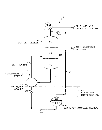
326~
4 2~
FI~. I ls ~ simplified schemAt:ic representatit)n of the portion of an
alkylation process comprising an a]kylation reactor riser, settler, cooler
heat exchflnger, and storage vessel illustrating such an arrangement suitab]e
for Cflrrying out the invention.
Referring to FIG. 1, there is il]ustrated a catalytic alkylation
apparatus and process. Because the carrying out of this invention is not
dependent upon the speciflc alkylation process operating conditions, such as
reaction temperature, reactor pressure, catalyst-to-hydrocarbon mixture
ratios, and isoparaffin-to-olefin mixture ratios and because these operating
conditions are well known in the art, they are not discussed in this
description.
Shown in FIG. 1 is system 8 for performing an alkylation process
which comprises settler vessel 10, riser-reactor 12, catalyst cooler 14 and
conduit 16 in fluid flow communication between the lower portion of the
settler vessel 10 and the catalyst cooler 14. Hydrocarbon feed material
comprising a mixture of olefins and isoparaffins is introduced through conduit
18 into the lower portion of the riser-reactor 12 which is in fluid flow
communication between the catalyst cooler 14 and the medial portion of the
settler vessel 10. The hydrocarbon feed material is introduced at essentially
the outlet of the catalyst cooler 14 where circulating liquid catalyst flows
by natural convection from settler vessel 10 via conduit 16 through catalyst
cooler 14 and mixes with the injected hydrocarbons from conduit 18 to form an
admixture. A presently preferred liquid catalyst for use in the system of the
present invention comprises a mixture of HF acid and water. The thus formed
admixture rises upwardly through riser-reactor 12 where the reactor effluent
discharges from riser-reactor 12 into settler vessel 10. Upon entering
settler vessel 10, two separate liquid phases form with the catalys-t phase 20
settling to the lower portion of settler vessel 10 and with the hydrocarbon
phase 22 forming above the catalyst phase and with a liquid-liquid :interface
24 being formed therebetweel-. The catalyst circulates con-tinuously through
the system by settling out in settler vessel 10 and passing through conduit
16, catalyst cooler 14, and riser-reactor 12.
In order to provide a safe, reliable and rapid method for
transfering alkylation catalyst from the alkylation process equipment without
using the catalyst storage standard approach of pressuring settler vessel 10
while simultaneously venting vessel 26 during the transfer operation, catalyst
326qlCA
~ J'~
storage vessrl 26 :is positioned at fl relative elevfltion below those elevations
of the alkylation process equipment comprising settler vessel 10,
riser-reactor 12, cat~~]yst cooler 14, and conduit 16. In one embodiment, the
catalyst storage vessel 26 can be positioned below ground level. This
elevation differential is shown at 28. Conduit 30 provides fluid flow
communication between the lower portion of catalyst cooler 14 and the lower
portion of catalyst storage vessel 26. During the draining operation, a
remotely operated valve 32, which is interposed in conduit 30, at a relative
elevation above cfltalyst storage vessel 26 but below said process equipment
comprising settler vessel 10, riser-reactor 12, catalyst cooler 14, and
conduit ]6, is opened to allow draining of catalyst by way of conduit 30. As
the catalyst is draining, the level of catalyst phase 34 in storage vessel 26
rises and the level of catalyst phase 20 in settler vessel 10 falls.
Vent line 36 interconnects the upper portion of the catalyst storage
vessel 26 and the upper portion of the settler vessel 10 to serve as a conduit
providing fluid flow communication between vapor space 38 of catalyst storage
vessel 26 and vapor space 40 of settler vessel 10. Vapor Space 40 of settler
vessel 10 is isolated from the downstream treating and flare systems (not
shown) by pressure safety valve 37. The pressure between vessels 10 and 26 is
equalized by the opening of a remotely operated valve 42 interposed in vent
line 36, which valve 42 is also used to isolate -the vapor spaces of vessels 10
and 26 when valve 42 is in its closed position. The opening of valve 42
during the draining operation results in the equali~ation of vapor space
pressure of the two vessels and thus allows the draining of catalyst from sa:id
process equipment to catalyst storage vessel 26 by the exclusive use of
gravitational motive force.
~2~9l(:A
fi
E~AMPI.E
The follow-in~ c~tlculated example is presented to il].ustrate the
application of the :inventlon on a commercial scale. Table I shows the
existi.ng conditions in the acid settler vessel along with the appurtenant
equipment, and it shows the conditions in the catalyst storage vessel. The
initial conditions indicated in Table I show the volume of cat:alyst in each of
the vesse].s, the initial vapor space pressures in each vessel, and the
relative liquid catalyst elevation in each vessel. Further shown are the
changes in conditions in each of the vessels as the invention is operated.
TABLE I
Initial Final Final
(W/0 (With
Venting) Venting)
Quantity of acid catalyst
in settler 10, riser-reactor
12, cooler 14, and piping400,000 lb150,000 lb 0
Pressure in vapor space
40 of settler 10 120 psia 110 psia111 psia
Level of acid catalyst 20 in
settler 10 and conduits connecting
catalyst storage vessel 26 relative
to level of acid catalyst 34 in
storage vessel 26 30 ft 10 ft-10 ft
Quantity of acid catalyst 34 50,000lb 300,000 lb 450,000 lb
Pressure in vapor space 38
of storage vessel 26 60 psia 115 psia 111 psia
Initially, before beginning the operation of draining catalyst frorn
the process equipment, there is generally a pressure differential between the
3~691(,A
7 ~02~
Vflpor spflce 40 of sett:ler vessel 10 and vapor space 38 of storAge vessel 26.
As the cfltalyst is dr~1ined from settler vessel 10, the liquid level elevation
differential between the two vessels changes and the non-condensable gases
present in vapor space 38 of stornge vessel 26 are compressed. This process
continues until the pressure between the two vessels equalizes and, in the
case where the storage vessel 26 elevation is below that of settler vessel 10,
the pressure in vapor space 38 of storage vessel 26 will rise to a point which
exceeds the pressure in the settler vessel 10 by the amount of the elevat,ion
head of the liquids in settler vessel 10. This results in equali~ing the
energy potentials at the liquid levels of the respective vessels 10 and 26.
The vent line 36, which connects the vapor spaces of the storage vessel 26 and
settler vessel 10, provides a conduit for the equalization of the pressure in
the vapor spaces of the two vessels. With an open vent line 36, the elevation
head of the catalyst remaining in the process equipment is further utilized to
drain the remaining catalyst into storage vessel 26 and thereby complete the
draining operation.
Reasonable variations and modifications may be made in the
combination and arrangement of parts or elements or in the processes as
heretofore set forth in the specification and shown in the drawing without
departing from the spirit and scope of the invention as defined in the
following claims.