Language selection

Search

Patent 2024786 Summary

Third-party information liability

Some of the information on this Web page has been provided by external sources. The Government of Canada is not responsible for the accuracy, reliability or currency of the information supplied by external sources. Users wishing to rely upon this information should consult directly with the source of the information. Content provided by external sources is not subject to official languages, privacy and accessibility requirements.

Claims and Abstract availability

Any discrepancies in the text and image of the Claims and Abstract are due to differing posting times. Text of the Claims and Abstract are posted:

  • At the time the application is open to public inspection;
  • At the time of issue of the patent (grant).
(12) Patent: (11) CA 2024786
(54) English Title: TURBINE NOZZLE, AND A METHOD OF VARYING THE POWER OF SAME
(54) French Title: TUYERE DE TURBINE ET METHODE POUR EN VARIER LA PUISSANCE
Status: Expired and beyond the Period of Reversal
Bibliographic Data
(51) International Patent Classification (IPC):
  • F02K 01/30 (2006.01)
  • F01D 09/04 (2006.01)
(72) Inventors :
  • KIMBERLIN, ROBERT R. (United States of America)
(73) Owners :
  • INGERSOLL-RAND COMPANY
(71) Applicants :
  • INGERSOLL-RAND COMPANY (United States of America)
(74) Agent: NORTON ROSE FULBRIGHT CANADA LLP/S.E.N.C.R.L., S.R.L.
(74) Associate agent:
(45) Issued: 1994-12-13
(22) Filed Date: 1990-09-06
(41) Open to Public Inspection: 1991-03-08
Examination requested: 1992-04-23
Availability of licence: N/A
Dedicated to the Public: N/A
(25) Language of filing: English

Patent Cooperation Treaty (PCT): No

(30) Application Priority Data:
Application No. Country/Territory Date
403,818 (United States of America) 1989-09-07

Abstracts

English Abstract


Docket No. 0639-IR-TH
ABSTRACT OF THE DISCLOSURE
The nozzle has a full complement of blades, for
use, for example, in a compressed-air turbine.
However, a pair of peripheral walls, at opposite
sides of the nozzle platform block nozzle blade
groups. The walls prevent fluid flow through those
blade groups and, consequently, the nozzle has
limited power. The method teaches the machining
away of as much of the walls as is necessary to
enhance the power of the nozzle by exposing more of
the nozzle blades to free fluid flow therethrough.
By providing such walled, fully bladed nozzles, and
removing portions of the walls, one can meet any
power requirement, from full power to any practical
minimum; by removing the walls entirely, or removing
only a minor portion of each, respectively.


Claims

Note: Claims are shown in the official language in which they were submitted.

The embodiment of the invention in which an exclusive
property or privilege is claimed are defined as
follows:
1. A turbine nozzle comprising:
a platform having a periphery defining a
substantially circular shape;
a plurality of equally spaced blades having
leading and trailing edges arrayed on said platform,
adjacent to said periphery and defining a plurality of
nozzle passages; and
a plurality of spaced walls integrally formed
about portions of the periphery of said platform,
integral with the leading edges of sequential ones of
said blades, for preventing a flow of fluid through
said nozzle passages.
2. A turbine nozzle, according to claim 1, wherein
said fluid flow preventing walls circumscribe no
less than approximately half of said plurality of
equally spaced blades.
3. A turbine nozzle, according to claim 1 wherein:
said plurality of blades extend normal to said
platform to a given height; and
said plurality of walls also extend normal to
said platform to substantially the same height
4. A method of increasing the power of a turbine
nozzle, comprising the steps of:
providing a turbine nozzle which includes a
platform having a periphery defining a substantially
circular shape, a plurality of equally spaced blades
having leading and trailing edges arrayed on the
periphery of said platform and defining a plurality of
nozzle passages adjacent to said periphery, and a
plurality of spaced walls integrally formed on the

periphery of the platform and integral with said
leading edges of said blades, for preventing a flow of
fluid through said nozzle passages; and
removing portions of said wall to permit fluid
flow through sequential ones of said nozzle passages.
5. A method of increasing the power of a turbine
nozzle, according to claim 4, wherein:
said turbine nozzle providing step comprises
providing said plurality of walls, as a pair of walls
on diametrically opposite sides of said platform.
6. A method of increasing the power of a turbine
nozzle, according to claim 4, wherein:
said wall removing step comprises removing
portions of said walls, until fluid flow is permitted
through the nozzle passages defined by approximately
half of said plurality of blades.

Description

Note: Descriptions are shown in the official language in which they were submitted.


A TURBINE NOZZLE, AND
A METHOD OF VARYING THE POWER OF SAME
BACKGROUND OF THE INVENTION
This invention pertains to fluid -turbines, and
in particular to (a) turbine nozzles, and (b) methods
of varying the power of such nozzlesO
Fluid turbines, for example, compressed air
turbines, are designed to meet varying power
requirements. A way o~ satisfyiny differing power
requirements is to configure the nozzles thereof with
differing numbers of blades. That is, for given
circumstances, a nozzle can be formed with X number of
blades for maximum power, X/2 for half power, and X/4
for one-quarter power.
; '
What has been long sought is a nozzle which is ~-
capable of meeting all possible power requirements. By
this, the necessity to manufacture and stock a supply
of variously bladed noz~les is ended.
~:
It is an object of this invention to set forth
the long souyht, universal power nozzle.
Concomitantly, it is also an object of this invention
to teach a method of varying the power of a turbine
nozzle
~.
SUMMARY OF THE INVENTION
According to a broad aspect of the present
invention there is provided a turbine nozzle which ~ -
comprises a platform having a periphery defining a
substantially circular shape. A plurality of equally
spaced blades having leading and trailing edges are
, ~ -
... :
~, .. : ,

arrayed on the platform, adjacent to the said periphery
and defining a plurality of nozzle passages. A
plurality of spaced walls are integrally forme~ about
portions of the periphery of the platform, integral
with the leading edyes of sequential ones of the
blades, for preventing a flow of fluid through the
nozzle passages. .
According to a still further broad a~pect o~ the
present invention there is provided a method of
increasing the power of a turbine nozzle and which
method , comprises the steps of providing a turbine
nozæle which includes a platform having a periphery
defining a substantially circular shape. A plurality
of e~ually spaced blades having leading and trailing
edges are arrayed on the perlphery of the platform and
define a plurality of nozzle passages adjacent to the
periphery. A plurality of spaced walls are integrally
formed on the periphery of the platform and integral
with said leading edges of the blades, for preventing a
flow of fluid through said nozzle passages. Portions
of the wall are removed to permit fluid flow through
sequential ones of the nozzle passages.
Further objects of this invention, as well as
the novel features and method steps thereof will become
more apparent by reference to the following
description, taken in conjunction with the accompanying
Figures, in which:
: BRIEF DESCRIPTION OF THE DR~WINGS
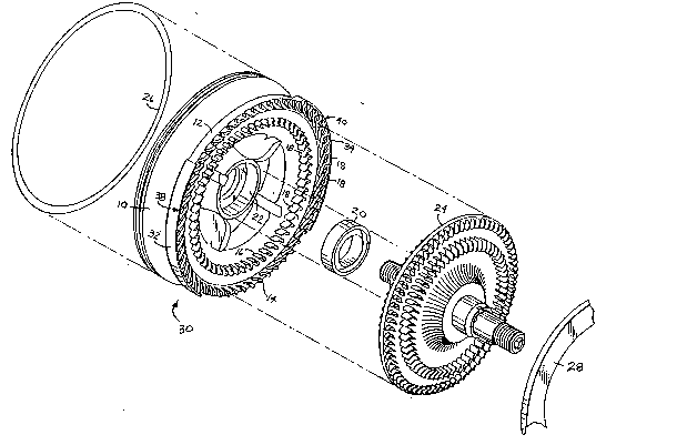
Fig. 1 is a perspective, exploded view of a
~ portion of a compressed air turbine, the same embodying
the invention; and
Fig~ 2 is a vertical illustration of the noæzle
of Fig. 1.
' ,
~ - 2 -
`::

~2~
Docket No~ 0639-IR~-TH
DETAILED DESCRIPTION
As shown in Fig. 1, an end plate 10, for a
compressed air turbine, comprises a plat~orm 12
which has two multiplicities 14 and 16 o blades
thereon. The blade~ 18 extend from the platform 12
05 in a normal attitude thereto. A rotor shaft seal 20
is received in the central rec~ss ~2 in the plat~orm
12, and a bladed rotor 24 is set into the seal.
A~ O-ring seal 26 sets against the end plate 10, and
a spacer 28, for a complementary end plate (not
shown), only a fragment thereof being shown, is
interposed between end plate 10 and the
complementary end plate.
The platform 12, as can be seen in Figs. 1 and
2, has a full complement of blades 18. Accordingly,
the blades and platform, comprising a nozzle 30, is
bladed for full power. However, a pair of walls 32
: and 34 are coupled to the periphery of nozæle 30, in
proximate adjacency to pluralities 38 and 40 of
blades. The walls 32 and 34, describing arcs of
equal length, inhibit a fluid flow through the blade
pluralities 38 and 40. The arc lengths of walls 32
and 34 are formed by machining away portions of the
as cast wall which completely circumscribe~ the
plat~orm 12.
As shown, the walls 32 and 34, having h~ights
; from the platform 12 substantially the same as the
heigh~.s of the blades 18 (as can be perceived in
Fig. 1), are each o~ approximately ninPty degrees of
arc. The nozzle 30, then, i5 capable of only about
:; 30 half its full power potential.

2~2~ o~86
Docket No. 0639-IR-TH
According to the novel method of the invention,
machining away the walls in their entirety will
provide nozzle 30 capable of full power.
Alternatively, by machining away half --
05 complementary halves -- o~ each of the walls 32 and
34 will render the nozzle capable of approximately
three-quarters of its full power potential.
According to this teaching, then, it is no
longer necessary to de~ign and construct nozzles
with diverse bladings. Fully complemented-bladed
nozzles can be fo~med with walls, like walls 32 and
34, which circumscribe half, three-quarters,
one-quarter, etc., as one chooses, of the blades
18. Then, by the simple expedient of machining away
so much of the walls as will power the nozzle to the
level required, a large number of power levels can
be provided.
While I have described my invention in
connection with a specific embodiment thereof, it is
to be clearly understood that this is done only by
way of example~ and not as a limitation to the scope
of my invention, as set forth in the objects thereof
and in the appended claims.
.
: - .
.: . : , . . ~ ~,
' ;. ' ' . .
.
.

Representative Drawing
A single figure which represents the drawing illustrating the invention.
Administrative Status

2024-08-01:As part of the Next Generation Patents (NGP) transition, the Canadian Patents Database (CPD) now contains a more detailed Event History, which replicates the Event Log of our new back-office solution.

Please note that "Inactive:" events refers to events no longer in use in our new back-office solution.

For a clearer understanding of the status of the application/patent presented on this page, the site Disclaimer , as well as the definitions for Patent , Event History , Maintenance Fee  and Payment History  should be consulted.

Event History

Description Date
Time Limit for Reversal Expired 2009-09-08
Letter Sent 2008-09-08
Inactive: IPC from MCD 2006-03-11
Grant by Issuance 1994-12-13
Request for Examination Requirements Determined Compliant 1992-04-23
All Requirements for Examination Determined Compliant 1992-04-23
Application Published (Open to Public Inspection) 1991-03-08

Abandonment History

There is no abandonment history.

Fee History

Fee Type Anniversary Year Due Date Paid Date
MF (patent, 7th anniv.) - standard 1997-09-08 1997-08-20
MF (patent, 8th anniv.) - standard 1998-09-08 1998-08-19
MF (patent, 9th anniv.) - standard 1999-09-06 1999-08-23
MF (patent, 10th anniv.) - standard 2000-09-06 2000-08-25
MF (patent, 11th anniv.) - standard 2001-09-06 2001-08-20
MF (patent, 12th anniv.) - standard 2002-09-06 2002-08-20
MF (patent, 13th anniv.) - standard 2003-09-08 2003-08-21
MF (patent, 14th anniv.) - standard 2004-09-07 2004-08-20
MF (patent, 15th anniv.) - standard 2005-09-06 2005-08-19
MF (patent, 16th anniv.) - standard 2006-09-06 2006-08-17
MF (patent, 17th anniv.) - standard 2007-09-06 2007-08-17
Owners on Record

Note: Records showing the ownership history in alphabetical order.

Current Owners on Record
INGERSOLL-RAND COMPANY
Past Owners on Record
ROBERT R. KIMBERLIN
Past Owners that do not appear in the "Owners on Record" listing will appear in other documentation within the application.
Documents

To view selected files, please enter reCAPTCHA code :


To view images, click a link in the Document Description column. To download the documents, select one or more checkboxes in the first column and then click the "Download Selected in PDF format (Zip Archive)" or the "Download Selected as Single PDF" button.

List of published and non-published patent-specific documents on the CPD .

If you have any difficulty accessing content, you can call the Client Service Centre at 1-866-997-1936 or send them an e-mail at CIPO Client Service Centre.


Document
Description 
Date
(yyyy-mm-dd) 
Number of pages   Size of Image (KB) 
Drawings 1997-10-11 2 76
Claims 1997-10-11 2 66
Abstract 1997-10-11 1 37
Descriptions 1997-10-11 4 165
Representative drawing 1999-07-08 1 36
Maintenance Fee Notice 2008-10-19 1 171
Fees 1996-08-18 1 38
Fees 1995-08-09 1 43
Fees 1994-08-11 1 64
Fees 1992-08-18 1 38
Fees 1993-08-12 1 41
Prosecution correspondence 1992-04-22 2 47
PCT Correspondence 1994-09-25 1 45
Prosecution correspondence 1993-05-30 2 68
Courtesy - Office Letter 1992-05-28 1 37
Examiner Requisition 1992-12-02 1 65