Note: Descriptions are shown in the official language in which they were submitted.
J ~
E'ILM UNWINDING CARRIAGE FOR A PAC~AGING ~C~TNh'
Machines are Xnown for pack~ging a load by means
of a web of deformable packaging film, comprising means
for supporting the load; a film reel which, when unwound,
makes it possible to supply film in web form; means for
supporting the film reel; and means for effe~ting a
relative displacement of the load (or of its supporting
means) and of the film reel (or of its supporting means)
for the purposa of ensuring that the load is covered wlth
the film. The film can cover the entire load or part o~
this. It can be solid or he open-work in the ~nn~r of a
net. The packaging can be more or less sealing or, on the
contrary, ventilated. The web can be of such a breadth
that a single turn is sufficient -to cover the load or, on
the contrary, of a smaller breadth, in which case ~he
packaging is usually helical with a plurality of turns.
The packaging can be reinforced in some places.
Typically, the packaging can in~olve the vertical faces
of a palletized load or the faces perpendicular to a
vertical plane. The packaging machine~ are of a type with
a linear relative movement of the load and/or of pivoting
type. In the latter ca~e, either the load pivots about a
vertical axis, the axis of the film reel Ll- ~ i n i ng
stationary, the table supporting the load being mounted
pivotably, or the axis of the film reel pivots about a
vertical axis round the load, the latter being stat-
ionary. Or the load is displaced horizontally along a
track passing through a ~ertical ring, on which the film
reel of horizontal axis is mounted. All the packaging
machinP~ of these types can be manual, semi-automatic or
automatic. In the latter case, they-generally have means
for the crosscutting of the film and means for fixing the
film to itself or to the load.
For exampla, to-lay a film web helically onto the
vertical faces of a palletized load, there is already a
proce~s known in which the load i~ brought onto a table;
the film coming from a film-reel of vertical axi~ carried
by a carriage is passed over -one or more rellers o~
vertical axes; then, in ~ucce~ion~ the initial free end
part of the film is fixed to the load; the table and
therefore the load are driven in rotation about a ~erti-
cal axis; and the carriage is driven upwards and
downwards between two upper and lower end positions in
relation to the rotation of-thé table; once the wrapping
has been completed, the film is cut transversely in the
vicinity of the load and the t~rmin~l free end part of
the film is fixed to the load or to the wrapped film.
A machine for carrying out this process is of the
type comprising a stationary stand; a load-receiving
table carried by the stand and mounted pivotably about
its vertical axis so as to be capable of selectively
being blocked in terms of rotation or dri~en in rotation
by driving and blocking mean5 and control means; a
stationary vertical mast carried by the stand and forming
a supportî bearings for supporting a film reel of verti-
cal axis which are carried by a carriage; rollers carried
by the carriage wh.ich is mounted slidably on the mast
vertically upwaxds and downwards between two upper and
lower end positions and which is driven slidably by
driving means associated with control mean~ associated
with the control means of the table.
The statP of the art is illustrated by some
machines of the series known under the trade-mark "DRA-PAL"
marketed by the companies of the NEWTEC lNl~KNATIONAL
group or machines of Messrs. MULLER MANUFACTURI~G. INC.
They are known to an average person skilled in the art as
being ~ch;nes for the vertical helical wrapping of a
palletized load on a turntable.
Also known are machines of another type (the
documents EP-A-0,177,413, FRA-1,220,712, US-A-4,109,445
and US-A-4,587-796 or the machine marketed by the ~EWTEC
IN~ATIONAL group under the trade-mark " DRA-PAL OCTOPUS" ),
comprising a stand, a table which supports the palletized
load in a fixed position during the wrapping of the load
and with which can be as50ciated means for the delivery
and the means for the discharge of the load, such as
roller conveyors; a moveable carriage for ~u~yoLLing a
film reel ~ a generally vertically directed axis;
J~r ~
: ~
-- 3 ~ 1 r~
mechanical means for supporting and guiding the carriage
which are:carried by the stand and which are such that
the carriage can be moved in a ~ v~...cnt occurring as a
result of the combination of a horizontal looping move-
ment around the load and of a vertical sliding; and meansfor driving the carriage which are capable of ensuring
its effective movement especially along an at least
substantially helical path of vertical axis surrounding
the load. The mechanical means for supporting and guiding
the carriage can have a plurality of alternative
embodiments: rotary arm ~the documents EP-A-0,117,413,
EP-A-0,220,712 and US-A-4,119,445) or horizontal frame
which surrounds the load and is moveable in a vertical
direction and along which the carriage is moved (the
document US-A-4,587,796), or an assembly moveable alony
a ring surronn~;ng the load. In one possible version, the
machine is not automatic (the document US-A-4,109,445),
and in this case the initial SQCuring of the film web to
the load, the final crosscutting of the film web and the
association of the terminal end part of the film web with
the wrapped load are carried out -nUAlly. In another
version, these operations are executed automatically, the
wrapping machine being automatic and for this purpose
possessing, carried by supporting means, means for the
crosscutting of the film web which are activated at the
end of the wrapping of the load; means ~or the temporary
retention of the initial end part of the film web coming
from the film reel which are active before the start of
wrapping; means for associating the tP in~l end part of
the film web with a wrapped load which are active at the
end of the wrapping; and means of retention and mean~ of
association (the documents EP-A-0,177,413 and
US-A-4,587,796).
With a ma¢hine of the latter type, a helical
~rapping of the vertical lateral faces of a palletized
load can be carried-out, and for.this purpo~e a load to
be wrapped i8 brought to and placed on the supporting
table in a fixed po~ition; the initial end part o~ the
film web c~ i~g from the film reel i~ ret~1ne~ ~gA~n~t a
~ 4 - 2l~7~f~7
vertical face of the load, ~he load always ~- ~in;n~
s~ationary, the film reel is unwound, and the load is
wrapped with the film web coming from the reel, the film
delivery rate being det~rmi ned so as to match the type of
wrapping carried out; this produces at least one turn of
film web on the load; the film web is cut transversely;
the t~rm;n~l end part of the film web is associated with
the wrapped load; and, on the one hand, the new initial
end part of the film web is retained and, on the other
hand, the wrapped load is discharged in such a way that
another wrapping process with another load can begin
again.
According to a likewise known embodLment, a
helical wrapping is carried out, at the start of the
wrapping process the film reel being in the lower end
position, that is to say in its relative position nearest
to the table in the vertical direction; the film reel is
then displaced in a rising helical movement about the
load until the film web oovers its vertical lateral
faces. Subsequently, a falling helical ~v~ ~nt o~ the
film reel is executed in order to produce a second layer
of film web covering and crossing over the first layer
produced during the rising helical wrapping, this taking
place until the film reel returns to its initial position
in the lower end position.
Preferably, and in accordance with the ten~n~y
which has been found, stretchable film, also possessing
the characteristic of being more or less self-adhesi~e,
is used. In this respect, the film is stretched longitud-
inally, especially beyond its elastic lLmit, and thusstretched is laid against the load. A plurality-of
techniques for the longit~]~;n~l stretching of the film
are known for this purpose: the conYe~ional technigue
using the relative braking of the film reel in relation
to the film ~ ~n~ defined by the load, or the more
recent technique, known a~ "prestretchingl', in which the
film is stretched independently o~ th9 load and for thi~
purpose, before being laid again~t the load, passe~ from
an upstream zone at a particular ~lnni ng ~peed to a
down~ream zone at a running ~peed higher khan the
preceding one. I'his technique of prestretching can he
carried out with a motorized or non-motorized prestretch-
ing device with two ups-tream and downstream rollers or
with a single roller, as-emerges from the documents
FR--A-2,281,275, FR-A-2,468,506, FR-A-470,056,
FR-A~2,289,780, FR-A-2,571,655 and FR-A-2,571,656 and
from the existence of a prestretching device--known under ~he
trade-mark "DYNA- DRAPEUR " marketed by the companies of the
ï O NEWTEC INTERNATIONAL group .
The film reel and the prestretching rollers
(where a prestretching device with a plurality of rollers
is concerned) are generally carried by a carriage, on
which they are in the vicinity of one another. Moreover,
this carriage is usually relatively near to the load or
to the other component members of the ~rth;ne. The result
of this is that access to the carriage and to the pre-
stretching rollers most often becomes difficult. This is
made even more complicated becau~e the prestretching
device also possesses guide rollers. This difficulty of
access makes the r~nll~l positioning of the film compli-
cated and lengthy. But it is also dangerous since the
prestretching rollers pi~ot in opposite directions, their
pivoting being sLmultaneous, so that the operator can
trap his fingers when the film is being positioned. This
positioning difficulty is also greatly increased by the
fact that the film is of large breadth (for example, of
the order o~ 40 to 70 cm), highly deformable and there-
fore without any inherent stability and, finally, to ~ome
extent self-a & e5ive. Thi5 problem is all the more
troublesome because the tendency to seek high degrees of
stretching (of the order of man~ times the elastic limit
of the film) and the generalization of these packaging
techniques (for example, also including those for loads
with cutting edges) make the probability that the film
will tear all the greater. A180, this problem in the end
affects the performances of these packaging techniques,
not only becau~e the po5itioning o~ the film require~ a
sub~tantial machine stoppage time, but al90 becau~e each
-- 6 - 2 ~J ~ l~ r~ ~ 7
positioning results in a waste o~ an appr~cia~le length
of film, just when the "high-technology~ films themselves
are more costly.
These problems of positioning the ~ilm have
already been raised, but have been solved only with
regard to the film reel alone (as is claLmed in the
document FR-A-2,573,059). This document provides an
apparatus for unwinding a reel of packaging ~ilm, having
a unwinding shaft designed for receiving the reel, a
drive system with rollers parallel to the shaft, and
stressing means for laying a driving roller of the drive
syst~m a~ainst the outer surface of the reel. The unwind-
ing shaft is supported by bearings at its upper end, and
its lower end is free. This unw-~i n~ shaft comprises a
radial clamping mech~ni~ consisting of fingers ar~icu-
lated on the unwinding shaft and actuated by a handwheel
located in an upper position. According to this document,
the positioning of the reel together with its finger
system and control handwheel is combined with a re-
tractable guide roller fixed to the drive system and
interacting with a stationary ramp in order to move the
drive system away from the shaft during a vertical
displacement of a ~upport of the drive system. A change
of reel therefore involves the following successive
steps: lowering of the support to bring the reel to the
ground; release of the handwheel; raising of the support
and disconnection of the reel and unwinding shaft; the
placing of a new reel on the ground; lowering of the
support; clamping of the handwheel; raising of the
support to lay this drive system against the reel;
lowering of the support after the retraction of the
roller. Consequently, with such a system the positioning
of the reel ~_ -i n~ especially complex and lengthy, the
more so because the structure of the unwinding apparatus
with which the document FR-A-2,573,059 is concerned
neces~itates a pre~sure contact (spxing) of the roller
drive system again~t the film reel.
With regard to a proce~ and a machin2 with a
prestretching of- the ~ilm ~y mean~ of a prestxetching
' ' ' ~ ~ ' " ' .
,
~ ' .
~ ~3 ~ 7
device, it has been proposed to use a film of original
breadth L:and subsequently to obtain a reduction of this
in order to bring it to a smaller value 1, the web laid
against the load being that of reduced breadth. The
breadth reduction provided by the state of the art is
obtained by passing the film web forcibly between two
rods arranged in a plane perpendicular to the film web
and perpendicular to the trace of the film web on ~his
plane. The two rods are spaced from one another by the
value 1, that is to say the reduced breadth. The two free
longitudinal edges of the film web moving along a wider
path than the spacing of the two rods interfere mechani~
cally with the two rods, thereby causing a ~'rolled
turnover~ of these edges on the~selves in the r~nner of
a rope. The film web of reduced breadkh thus has a
central part without any substantial modification and
with the central part of the web of original breadth and,
on its two longitudinal edges, two "rolled turnover~"
forming a kind of hem~ This state of the art.is well
illustrated particularly in the documents GB-A-2,069,957,
US-A-4,204,377, US-A-4,235,062 and US-A-4,325,918.
It was found that, contrary to the teachings of
the state of the art, it was not always desirable, and
indeed was even somewhat disadvantageous, to produce a
film web of reduced breadth by calibrating the film and
by forming longitudinal "rolled turnovers" at its edges:
in fact, the thickness of the film web varies to too
great an extent, and this can a~fect the packaging; the
breadth obtained is not always uniform; there is an
appreciable ~riction of the film web on the rod More-
over, it becomes all the more difficult to obtain such a
breadth reduction because the problem of positioning the
film in the pre~tretching device is itself complex, as
already mentioned.
The object of the invention i5, therefore, to
solve the problems arising from the use of a packaging
film, especially the positioning of the film and the
reduction of its breadth.
To achieve this, the inven-tion provide~ a proces4
: . ' ' .
'
.
r~ ~ 7
for using a carriage for unwinding pac~aging ~ilm,
compri~ing ~ stand; a supporting shaft for a film reel
to allow the pivoting of the reel and the unwinding of
the film; a device with rollers of axes parallel to that
S of the supporting shaft; this carriage being intended to
be incorporated in a packaging machine; this process
involving:
- an initial phase for as~ociating a reel with a support-
ing shaft;
- a ~ubsequent phase for positioning the film web in the
roller device comprising two upstream and downstream main
rollers, defining between them a passage having an entry
oxifice and an exit orifice and designed to pivot about
their axes in opposite directions, and two upstream and
downstream guide rollers of axes parallel to the axes
which in their operational location are respectively set
apart ups~ream from the entry orifice and downstream from
the exit orifice,
- a phase of unwinding the film for the packaging of the
load, wherein, in the phase of positioning the film web:
* th~ starting point is an initial state in which the
upstream and downstream guide rollers are relatively
displaced from their final operational location to a tem-
porary initial positioning location, where they are
respectively nearest to the entry orifice and to the exit
orifice;
* in an initial introduction phase, an initial end of the
film is introduced between the upstream main roller and
guide roller and in the direction of the downstre~m main
roller;
* in a subsequent running phase, the upstream and down-
stream main rollers are pivoted about their axes, and a
particular length of film is made to run in the direction
of its introduction into the device;
* and in a flnal positioning phase, a~ a result of a
r~lative displacement the upstream and downstream guide
roller~ are brought from their initial location to their
final operational location, the effect of this being to
bend the film, at the ~ame time. laying it against the
' ' ' . ',~' ' :
- : :
.
~ '
upstream and downstream main rollers.
The invention also relates to a carriage -for
unwinding packaging film, comprising a stand; a support-
ing shaft for a film reel carried by the stand; a roller
device carried by the stand and of axes parallel to that
of the supporting shaft; this carriage being intended to
be incorporated in a packaging machine; the roller device
comprising two upstream and downstream main rollers set
transversely apart and of parallel axes, but near to one
ano~her, defining between them a passage for the packag-
ing film and having an entry orifice and an exit orifice,
said main rollers being designed to pivot simultaneously
about their axes in opposite directions by appropriate
means; two upstream and downstream film guide rollers
which are associated with the upstream and downstream
main rollers and the axes of which are parallel to one
another and to the axes, in their .final operational
location, said guide rollers being respectively moved
away upstream from the entry orifice and downstream from
the exit orifice, wherein there are, carried by the
~tand, selectively controlled means for displacement with
blocking, capable of allowing a relative displacement,
with blocking in one of the two end postitions, of the
guide rollers in relation to the axes of the main
rollers, the guide rollers being either in the final
operational. location or in a temporary initial posit-
ioning location, where they are associated with the main
rollers respectively nearest.to the entry orifice and to
the exit orifice.
The other characteristics of the invention will
emerge from the.description which follows with reference
to the accompanyiny drawings in which:
Figures 1 to 6 are six diagrammatic axial end
views of a carriage according to the invention (only the
main rollers and the guide rollers are show~) at a
plurality of successive moments in.the phase of po~tion-
ing the film, namely Figure 1 illustrates the temporary
initial location of the guide roller~ and the inikial
delive~y o~ the film; Figure 2 .illustrates. khe initial
~ ,'. ' '
:
- 10 - ~ r~
phase of introducing the -film, with the guide rollers in
this same location; Figure~ 3 and 4 illustrate the
running phase, still with the guide rollers in this same
location; Figure 5 illustrates an intermediate posi-tion
in the final posi'ioning phase; and Yigure 6 illustrates
the operational device, the guide rollers ~eing in their
final operational location, the film traveling through
the device.
Figure 7 is a simplified partial elevation view
of a carriage according to the invention, showing the
means for positioning the film.
Figure 8 is a partial top view of the carriage of
Figure 7, illustrating an alternative version of the
means capable of allowing the displacement of the guide
rollers.
Figure 9 is a partial bottom ~iew of the carriage
of Figure 7, illustrating an alternative version of means
capable of allowing a differential speed of the two
prestretching roll2rs thigher downstream than upstream).
Figure 10 is a partial diayr- -tic elevation
view of the upper part of the carriage according to the
version of Figure 8, showing the means capable of
allowing the displacement of the guide rollers and their
arrangement.
Figure 11 is a partial view on a larger scale,
illustrating the mounting and arrangement, according to
one possible version, of a mai~ roller and of the associ-
ated guide roller.
Figure 12 i5 a view comparable to that of Figures
1 to 6, but on a larger scale, the introduction state~
being represented b~ da5hes and the operational state~ by
dot-and-dash line~, both an regards the guide rollers and
as regards the film.
Figure 13 is a diagrammatic per~pective view of
one of the possible versions of- a packaging machine
receiving the carriage according to the invention ~a
machine of the type with a turntable rotating about a
verticaI axis). '
Figures 14 and 15 are respectively two partial
', ~ , -
:
.. . . .
.
.
.
'
diagrammatic elevation and axial end views of another
version o~ the means capable o~ allowing the displac~ment
of the guide rollers (a version with a pivoting fram~).
Figure 16 is another diagrammatic axial end view
of another version of these means (a version with a
rotary ring).
Figure 17 is another diagrammatic axial end view
illustrating another version of these means (a version
with links of offset pivot axes).
Figure 18 is a part view, partially in elevation
and partially Ln section, of a carriage according to the
invention, illustrating a version of a device for
blocking a film reel on the supporting shafk.
Figure 19 is a partial diagrammatic per~pective
view of a carriage according to the invention, illustrat-
ing the longitudinal creasing means which it possesses.
Figure 20 is an elevation view of the carriage
according to Figure 19.
Figures 21A, 21B and 21C are three dia~l -tic
cross-sectional views of a web of the stretchable film
used in the invention, in three possible states respec-
tively initially (when stored on or unwound from the
reel), after the contraction of the breadth, but before
stretching, and finally afte- contraction and stretching.
Figure 22 is a diagrammatic elevation view of a
possible version of a packaging machine having a carriage
according to the invention (a machine of the rotary arm
type).
Figures 23A, ~3B and 23C are three diagrammatic
plan and elevation views of an unwound portion of a
stretchable film web, as used in the invention, with
three possible degrees: initially, that is to say without
a contraction of the breadth, with some contraction of
the breadth, and finally with a greater contraction.
Figures 24A, 24B and 24C each show four end views
of the unwound portion of Figure~ 23A, 23B and 23C
respectively in four different successive locations from
upstream in the downstream direction, namely the film
stoxage reel, the means for contracting the breadth, khe
' ' ' '
12 - ~ r)~ ~
entrance of an upstream preskretching roller and the exit
of a downstream prestretching roller.
Figure 25 is a partial perspective view illus-
trating hooks of a carriage according to the invention
for the longitudinal reinforcement of the ~ilm web before
its stretching.
The invention is concerned with the use of a
carriage 14 for unwinding packaging film 1 in web fo~n.
The carriage 14 comprises a stand 10 which
supports the various memher~ composing it. A supporting
shaft 42 for a film reel 15 is associated with it, in
such a way that the film reel can pivot about i~s axis
for the unwinding of the film 1.
The carriage 14 is intended to be incorporated in
a machine for packaging a load tFigures 13 and 22) by
means of the film 1.
This machine comprises a stand 12, means 13 for
suppor~ing a load to be packaged with the film 1, the
carriage 14 and the means 16 for ensuring the relative
displacement of the load in relation to the film 1 or to
the reel 15, so as to allow the load to be appropriately
covered with the film 1.
Such a packaging machine can be especially of one
of the following types~ curtain machine; turntable
machine; machine with a stationary table and with a reel
of an axis rotating about the load; machine with a
vertical ring and a track passing through the ring.
As regards the curtain machine (not shown), the
packaging involves the vertical faces of the load, such
as a palletized load. The load is moved along a horizon-
tal path towards a vertical curtain of film ext~n~; ng in
a horizontal direction transversely relative to the
direction of movement of the load. The machine is sym--
metrical in relation to the longitu~i n~ 1 vertical plane,
ànd it has two film reels of stationary vertical axes.
The ~ch;ne possesses two carriages, such as 14, support-
ing the ~aw~ for the crosscutting and tran~ver~e fixing
ofthecurtainoffilmand,where a~pLup~iate, pre~tretching
devices when a prestretched stretchable film is used.
,
- 13 ~ 7 ~ ~
Where a turntable machine (Figure 13) is con-
cerned, the stand 12 has a base 12a for supporting the
table 13 and an offset vertical column 12b carrying the
carriage 14 which supports the reel 15, the shaft 42
being vertical. According to one possible version (not
shown), the carriage 14 is stationary in the vertical
direction, either because the film web 1 has a width
equal to the height of the load to be palletized or
because the packaging is a local hooping. According to
another possible version (as shown), the carriage 14 is
mounted slidably upwards and downwards along the column
12b, the sliding movement being coordinated with the
rotational movement of the table 13 by driving means 16,
such as a motor or geared motor. Such a machine can have
additional members, such as grippers for holding the film
1 and cross-cutking and fixing jaws 17 or a presser 18.
As regards a machine with a stationary table and
a film reel with an ~xis rotating about the load
(Figure 22), the stand 12 has vertical pillars 12c placed
round the table i3 and supporting a superstructure 12d in
their upper end parts. This stand 12 supports in a
suitable way a film reel 15 rotatahle about the load. In
a first version, the movc ~nt is only horizontal (at one
or more heights or levels). In a second cu~tomary ver-
sion, the J.~V. ~nt is helical in order to ensure ahelical wrapping of the lateral ~aces of the-palletized
load to be packaged. The carriage 14 is carried by a
moveable structure 43 particularly supporting the film
reel 15 and allowing the reel 15 to move about the load.
This structure 43 i~, for example, a horizontally move-
able arm 43a carried by the superstructure 12d above the
load. Located at the end opposite that where this arm is
mounted pivotably on the superstructure 12d is a column
43b spaced horizontally apart from the ~ertical faces of
the load, but located opposite it, the carriage 14 thus
generally being capable of sliding along this column 43b
spaced horizontally apart from the vertical face~ of the
load, but placed oppo~it~ it, the carriage- 14 thus
generally being capable o~ sliding a-long thi~ column 43b
~3 ~
~as in Figure 22). There can also be members, such as
grippers, jaws, pressers, 17, 18. According to another
example (not shown~, the structure possesses a first
frame mounted vertically slidably and having guides for
a ring carrying the carriage rigidly, the frame having
such an orifice that it can be placed round the load.
According to another example (not shown), the structure
has a ring which is mounted vertically slidably and is
capable of surrounding the load and on which is mounted
a carriage displaceable along this ring.
The film 1 can have alternative forms: its
breadth can be greater or lesser. It can be continuous,
without perforation, or perforated in the ~nn~r of a
net. It can be shrinkable or stretchable. The packaging
can cover all the faces of the load or only part of
these. The packaging can be single-layer or multilayer in
a uniform m~nner or not. For example, it can comprise an
inner wrapping in one direction and an outer wrapping in
the opposite direction and crossed. A plurality of
wrapping layers can be provided in the vicinity of the
non-covered end face~.
The packaging machine can be automatic or ~n~
The presence of a jaw or a gripper, such as 17, is
characteristic of an automatic machine which then posses-
ses a proyL- -d automatic control ~k; ng it possible to
execute pro~l -d cycles adaptable according to the
types of load, film 1, packaging to be carried out.
~ ccording to a prefexred, but not exclusive,
altPrnative embodiment, a stretchable film is used and is
stretched beyond its elastic limit before being laid
against the load. The packaging machine then has means
capable of carrying out this stretching and the packaging
process a step invol~ing stretching the film longitudi-
nally. The stretching can be carried out in various
alternative ways, especially and preferably by that known
in the state of the art as "prestretching" (the document
FR-A-2,281,275). In thi~ case, the film 1 i~ passed
through the location of the carriage 14 at an upstream
rl~nning speed lower than a higher downstream running
.. ~
' ~
- 15 - 2 0 2 ~
speed. The prestretched film 1 i5 then transporked t:o the
load. In-this case, the machine possesses a prestretching
devic~ having generatrices such that ~he film is
displaced from the entrance of the prestretching device
to the exit from an upstream running speed to a down-
stream running speed higher than the upstream speed. This
prestretching device is generally located on or
associated functionally wi~h the carriage 14. All the
alternative embodiments of prestretching devices
according to the known state of the art can be con-
sidered. For example, the prestretching device can be of
the non motorized type, the drive being obtained by the
~-~ov- ~nt of the film 1 itself. Or it can be of the
motorized type with a motor driving the generatrices of
the prestretching device. It can be of the type compris-
ing at least one upstream roller and one downstream
roller arranged so that the circumferential speed of the
downstream roller is higher than ~hat of the upstream
roller, or of the type with at least one single roller,
the generatrices of which are at a higher circumferential
speed downstream than upstream.
Reference will now be made more specifically to
Figures 1 to 17 which relate to the positioning of a web
of packaging film 1 in a roller device 2 comprising, on
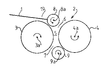
the one hand, two upstream and downstream ~ain rollers 3,
4 set transversely apart and of parallel axes 3a, 4a
parallel, but near one another, d~fining between them a
passage 5 ~or the film 1 and having an entry orifice 6
and exit orifice 7, said main rollers 3/ 4 being designed
to pivot simultaneously about their axes 3a, 4a in
opposite directions, and, on the other hand, two upstream
and downstream ~ilm guide rollers 8, 9 of axe3 8a, 9a
parallel to the axes 3a, 4a associated with the upstream
and downstream main rollers 3, 4 and, in their final
operational location, being respectively moved away
upstream from the entry ori~ice 6 and downstream from the
exit orifice 7, in such a way that, in the roller device
2, the film follows an S-shaped path, going ~rom up~tream
in the down~tream direction from the up~traam guide
- 16 - 2~ 7~
roller 8 to the downstream guide roller 9, passing
successively via a particular sectox of the upstream main
roller 3, the entry orifice 6, the passage 5, the exit
orifice 7 and a particular sector of the downstream
roller 4. The invention also xelates to the carriage 14
of a packaging machine, such as has been described,
comprising sl~ch a roller device 2 and supported by the
stand 10, the main rollers 3, 4 being designed to pivot
simultaneously about their axes 3a, 4a in opposite
directions by means 11 provided for this purpose.
By convention, in the text the r~ferences
~upstream" and ~'downs~ream" refer to tha normal running
direction of th~ film 1. Also, the term ~axis'i for a
roller refers both to the imaginary straight line about
which the roller pivots and to the actual shaft or
journal allowing this pivoting.
The process for using the carriage 14 having such
a device 2 and the carriage 14 according to the invention
are intended to be employed within a process or a machine
lmore generally a device or installation) for the packag-
ing of a load by means of a plastic film in web form, as
already described, particularly, but not solely of the
type illustrated in Figure 13.
The carriage 14 supports the reel 15 and, in the
vicinity, the roller device 2 according to the invention
which preferably functions as a device for the longitudi-
nal stretching of the film ~ and, more especially, for
prestretching.
To xeturn to the machine version illustrated in
Figure 13, this functions as follows: the presser 18
carried freely pivotably on an arm mounted on the mast
12a via a vertically sliding carriage is raised. With the
table 13 stopped, the load is brought onto it tby means
of a conveyor (not shown) or a transporter carriage). The
presser 18 is lowered onto the upper horizontal face of
the load. Th~ initial end of the film 1 coming from the
reel is fa~tened to the gripper 17. The motors o~ ths
means 16 are controlled in ~uch a way that the table 13
is driven in rotation, while the carriage 14 is driven
- 17 - ~3 2 ~
from the vicinity of the gripper 17 (usually ~ear the
table 13) to the opposite end o~ the load (usually the
upper horizontal face of ~he load). The breadth of the
film web 1 is a fraction of the height of the load. The
setting in motion causes the helical wrapping of the load
(its vertical faces~. The movements are continued until
the carriage 14 returns to its original position. The
gripper 17 is designed for holding and transversely
cutting the film web 1 and for laying the termin~l end of
the film 1 against the load OL the film web 1 already
laid onto the load. The presser 18 can then be raised and
the packaged load discharged from the table 13. The film
1 coming from the reel 15 passes over the rollers of the
device 2 functioning as a prestretcher. As will be
appreciated and as can be seen in Figure 13, the device
2 is difficult of access, being located on the inner side
of the mast 12a (towards the turntable 13), if appropri--
ate between the mast 12a and the load if the table 13
supports such a load. It will therefore be appreciated
that it would be expedient to have a more automated
positioning of the film web 1 coming from the reel 15,
via the roller device 2, in which the path of the film is
tortuous and complex (generally S-shaped).
As regards a stretchable plastic film 1 pre-
stre~ched by means of two prestretching rollers, there
are: an upstream roller having a particular upstream
peripheral speed and a downstream roller having a higher
peripheral speed. Respective upstream and downstxeam
yuide rollers associated against the upstream and down-
stream prestretching rollers respectively, with the filminterposed between them, ensure that the film 1 is in
contact with the prestretching rollers over a sufficient
arc of a circle (for example, approximately 180~). The
prestretching rollers preferably ha~e a catching outer
surface to pre~ent or limit the sliding of the-film 1
onto them. Moreover, they are generally close to one
another, to limit the con~triction of the film 1 a~ a
result of its ~tretching. At the present t~e, the
spAci~g between the pre3tretching roller~ i~ greater than
.~
. .
~ ~3 7 ~ J $ ~
1~
necessary for -the stretching function, in order to ~llow
access ~etween them for the operator~s fingers during the
positioning of the film 1. The prestretching rolle~s can
b~ of the same diameter ~r of different diameters. They
can be positively motorized or driven by the running
film. C~mm~n~, adjustment, control and manitoring
members can also be provided. ~urthermore, the stre~ching
can be carried out in a plurality of steps, in which case
a plurality of prestretching rollers is provided~
10The invention is preferably used when such
prestretching devices are employed. In this case, the
~ roller device 2 also forms or is incorporated in the
prestretching device. This means that the upstream and
downstream prestretching rollers are formed in the same
way as and are the same as the rollers 3, 4 of the device
2. Also, the guide rollers of the prestretching device
are formed in the same way as and are the same as the
rollers 8, 9 of the device 2.
Thus, all the alternative versions known to or
within the scope of an average person skilled in the art
as regards the prestretching devices with two rollers at
differential speeds can be used for the device 2. Or,
conversely, the device 2 can have the various structures
known to or within the scope of an average person skilled
in the art for the prestretching devices with two rollers
at differential speeds. Consequently, the ~tructure of
the roller device 2 and its various alternative versions
or imp~ov. -nts are not described in detail here, insofa.r
as it is identical and common to that of a prestretching
device with rollers at differential speeds which is known
to or within the scope of an average person skilled in
the art. In contrast, the specific features ~king it
pos~ible to adapt such a prestretching device so that it
represents the structure and characteristics desired for
forming a device 2 according to the invention are
de~cribed~ .
Moreover, it must b~ understood that, although
the device 2 i~ derived ~rom a pre~tretching device and
perform~ thi~ pre~tretching function, it can also be
,
19 ~ J ~
independent of or separa~e fLom ~his. Ln other words, it
is conceivably possible for the rollers 3, 4 to have the
same peripheral speed, for the film 1 not to be stretched
longitudinally during the passage through the device 2,
and moreover for the film 1 used not to be a stretchable
film. For example, the de~ice 2 can serve only for the
correct positioning of the film 1.
The description which ~ollows refers to the
instance where the device 2 functions as a prestretcher
with two rollers 3, 4 at differential speeds and of the
same diameter.
Reference is now made to Figure 6 (or to Figure
12 in the form of dot-and-dash lines) which shows a
prestretching device, hence the device 2, in its normal
operational functioning.
Bearing in mind what was said before, the stand
10 o~ the carriage 14 supporting the device 2 also
supports the film reel 15. The film 1 used in the device
2 according to the invenkion comes from the film reel 15-
preferably located in the vicinity of the device 2, asfar as the requirements of access and of overall size
allow. The means 11 for driving the rollers 3, 4 consist
of the film 1 which is laid against the rollers 3/ 4
without sliding and which thereby drive them in rotation
during its run, and of separate mechanical and/or
electric means ensuring the coupling of the rollers 3, 4
to one another and/or their positive drive. Moreover,
these means 11 ensure the pivoting of the rollers 3,4 at
the same peripheral speed or, where a prestretching
device is concerned, at differential speeds, as already
explained.
The starting point i~ an initial state, in which
the guide rollers 8, 9 are relatively displaced ~rom
their final operational location to a t~- ~olary initial
positioning location where they are associated with the
main rollers 3, 4 nearest to the entry orifice 6 and the
exit orifice 7. In an initial introduction phase, an
initial end 19 of the fi~m 1 i~ introduced between the
ups~ream main roller 3 and guide roller 8 and in tho
' . ~ -
'
- 20 ~
direction of the downstream main roller 4. In a subse-
quent running phase, the main rollers 3, 4 are pivoted
about their axes 3a, 4a, and a particular length of film
1 is made to run in the direction of its introduction
into the device 2. And in a final positioning phase, as
a result of a relative displacement the guide rollers 8,
9 are brought from their temporary initial positioning
location to their final operational location, the effect
of this being to bend the film 1, at the same time laying
it against said sectors of the main rollers 3, 4.
As seen parallel to the axes 3al 4a (the plane o~
Figures 1 to 6 and 12), the space between the sectors of
the outer lateral surfaces 20, 21 of the rollers 3, 4
spaced apart from, but near to and opposite one another
has the general form of a Venturi tube or of a conver-
gent-divergent nozzle. This space defines the passage 5.
This passage is narrowest at the location of the
generatrices nearest to the surfaces 20, 21 or in the
plane P connecting the axes 3a, 4a. This passage 5 is ~he
widest on either side of the plane P substantially in the
planes QE and QS tangential to the two surfaces 20, 21,
as can be seen in Figure 12. The entry orifice 6 is on
the same side as and near to the plane QE, while the exit
orifice 7 is on the same side as and near to the plane
QS. An orifice 6, 7 is referred to re~pectively as an
entry or exit orifice according to the direction of
rotation of the rollers 3, 4, a~ represented by arrows in
the Figures. For entry, the direction of rotation of the
rollers 3, 4 is towards the plane P, while for the exit
the direction of rotation of the rollers 3, 4 is in the
opposite direction to the plane P.
The temporary initial location-of the guide
rollers 8, 9 can be seen in Figures 1 to 4 and is repre-
sented by dashes in Figure 12. For example, a typical
position of the guide rollers 8, g in this temporary
initial location is such that they are partially in the
passage 5; that is to say, they are secant relative to
the planes QE and QS respectively, or they are partially
opposite the rsspective sectors of the main roller 3, 4
- 21 - 2 ~
with which the~ are not associated. For example, (Figure
12), the rollers 8, 9, in their temporary initial lo-
cation, are-tangential or su~stantially tangenkial to khe
rollers 3, 4 at the point or in the vicinity of the
tangent generatrices of the rollers 3, 4 through planes
R and S passing through the axes 4a and 3a respectiv~ly.
That is to say, these planes R and S passing through the
axes 4a, 3a are also substantially tangent planes o~ each
pair of upstream rollers 3 and 8 and downstream rollers
4 and 9.
By the fact that rollers 3, 8 on the one hand and
4, 9 on the other hand are associated with one another is
meant that they are arranged in relation to one another
so as to be capable of interacting together, with the
film 1 placed between them. This association includes the
fact that the rollers are tangent (with the exception of
the thickness of the film 1) or are near to one another
or laid against one another. The notion of tangency is
taken to refer to rollers considered in terms of their
envelope, in view of the fact that the outer surface of
the rollers can be in relief, such as embossed, to
prevent the film 1 from sliding.
To bring the guide rollers 8, 9 from their final
operational location to their initial operational lo-
cation, their axes 8a, 9a are moved substantially to
pivot about the axes 3a, 4a, each by a fraction of a
revolution, e~pecially a half-revolution or substantially
a half-revolution, p~rticularly a little more than a
half-revolution, in the direction of rotation of the
rollers 3 and 4 respectively.
The initial introduction phase i5 illustrated in
Figure 1. The film 1, more specifically its initial end
19, is brought from the opposite side towards the main
roller 4 substantially in the plane R already defined.
The subsequen~ phase is illustrated in Figures 2,
3 and 4 in three successive ~tates. The pivoting of the
roller 3 and the association with the guide roller 8 or
the inherent drive of the fiLm 1 cau~e the ~ln~ing o~ the
film l, the initial end 19 o~ which approaches and then
-- 22 2 t~ rJ ~ i ~
comes in contact with the outer sur~ace 21 of the roller
4, especially substantially along or in the vicinity of
the generatxix 22 of intersection of the plane R with the
outer surface 21 (called the impact generatrix). The
pivoting movement of the roller 4 and the friction
between the film 1 and the roller 4 cause the end 19 to
be driven towards ~he narrowed part of the passage 5, and
then from this ~owards the other guide roller 9 located
in or in the vicinity of the exit orifice 7 (Figure 2).
Because of the pivoting direction of the rollers 3, 4 and
9, the film 1 (namely its end 19) is prevented from
passing between the rollers 3 and 9 and, on the contrary,
is stressed so as to pass between the rollers 4 and 9
(Figure 3). The running ~v~ -nt of the ~ilm 1 can then
be continued, and the length of film 1 pro~ecting from
between the rollers 4, 9 is then at least equal to the
fraction of circumference of the roller 4 against which
the ~ilm 1 is to be laid during normal operation (Figure
4) or, more generally, at least equal to that of the path
of the film 1 in the device 2. For this purpose, during
the subsequen~ running phase, the main rollers 3, 4 are
pivoted aDOUt their respective axes 3a, 4a by at least a
-' fraction of a revolution.
The final phase is illustrated in Figure 5,
corresponding to an intermediate situation of the guidë
rollers 8, 9 between the temporary initial location
(Figures 1 to ~) and the final operational location
(Figure 6). For this purpose, the guide rollers 8 and 9
are displaced pivotally about the axes 3a and 4a in
opposite directions to the directions of rotation of the
main rollers 3 and 4, with mov~ ?nts equal and opposite
to the initial l..OV. -nts which brought the same rollers
3, 9 from their final operational location to the tem-
porary initial location. During this -v.- -nt o~ the
guide roller 8, 9 a~ far a~ their final operational
location, they retain the film, and the effect of thi~ is
to lay the film progres~ively onto khe sector~ of the
outer sur~ace~ 20 and 21 o~ the roller~ 3 and 4 contained
sub~tantially between the temporary initial location~ and
rl ~ r;~
-- 23 --
the final operational locations.
The final operational locations of the guide
rollers 8, 9 are respectively set apart from the entry
orifice 6 and exit orifice 7, 50 that the film 1, as it
passes from the roller 8 to the roller 4, follows a path
in the form of a more or less open or closed S. Moreover,
this path becomes possible to obtain easily, quickly and
reliably, without the operator having to in~ert his
fingers into the passage 5. In the passage 5, the film 1
follows a path coinciding substantially with the tangent
plane connecting the rollers 3 and 4 in this passage 5.
The device 2 is symmetric relative to an axis of
symmetry 23 located in the passage 5 at the intersection
of the plane P and of a plane T located between and
equidistant from the rollers 3, 4. In this cas~, in the
final positioning phase, a relative displacement of the
guide rollers 8,'9 and main rollers 3, 4 is carried out
simultaneously.
The upstream and downstream guide rollers 8, 9
are allowed permanently to pivot freely about their axes
8a, 9a. These rollers 8, 9 are therefore driven as a
result of friction with the r-~nn;ng film. Furthermore,
during the running phase, the main rollers 3, 4 are
positively driven to pivot about their axes 3al 4a.
~5In the temporary initial positioning location,
the guide rollers 8, 9 are brought into the entry and
exit orifices 6, 7 respectively. More especially, the
rollers 8, 9 are spaced transversely apart from the main
rollers 3, 4 by a distance at least equal to the order of ~:
thickness of the film. That is to say, the spacing of the
main rollers 3, 4 and of the associated guide rollers 8,
9 is substantially equal in the two initial an~ final
locations.
During the initial introduction phase r the main
rollers 3, 4 are posi~ively driven ~o pivot. During the
same running phase, the initial end 19 o~ the film 1 is
grasped downstream of thQ pa~sage between the down~tream
main rollar 4 and the down~tream guide ro~ler 9, a~ soon
as the downstream guide roller 9 is in it~ temporary
:
.
- _ 24 -
initial positioning location, and it is pulled in its
running direction by exerting a pull on it. This pull is
represented by the arrow Fl in Figure 3. This pull is
intended for controlling the run of ~he film 1. It can be
exerted manually. There is no danger in this since the
operator~s fingers go in a direction away from th~
rollers 9, 4 which themselves pivot at this point in
opposite directions to the pinching of ~ingers. Con~
versely, to give the film some tension, but in any event
to prevent it from being slack, a particular retaining
tension is exerted on the ~ilm 1 upstream in the opposite
direction to its run. This retaining tension is repre~
sented by the arrow F2 in Figure 3. It can be exerted
automatically by means of a slight braking as a result of
friction exerted on the film reel 15 from which the film
1 has come.
In the final positioning phase, a relative
displacement of the guide rollers 8, 9 and of the main
rollers 3, 4 is obtained by keeping the guide rollers 8,
9 in the ~icinity of the main rollers 3, 4. Alterna-
tively, the guide rollers 8, 9 are in the vicinity of the
main rollers 3, 4 only in the two initial and final end
locations, but--are set apart from them in the inter-
mediate locations. At least in the ~inal operational
location, the guide rollers 8, 9 are brought substan-
tially against, especially to bear against the main
rollers, with the film 1 interposed between them. But
this bearing is generally also carried out in the initial
location and in the intermediate locations.
Because there is no need to have access to the
pa~sage 5, it is possible to reduce the spacing between
the rollers 3 and 4 strict~y to a minimum, and therefore
the main roller~ 3, 4 are arranged with a transverse
spacing substantially equal to the mini - distance
allowing the film 1 to run between the two of them. Thi~
constructive characteristic is especially important when
the device 2 is al~o a prestretcher, because it make~ it
po~sibl~ to reduce the length of ~ilm 1 in the pa~sage 5
and therefore the constrict~on occurring as a result of
2 ~ ' J ~ ~
- 25 -
the longitudinal stretching.
In the final positioning phase, the axes o~ a
first pair of main rollers 3, 4 and guide rollers 8, 9
are kept stationary and the axes of a second pair of
guide rollers 8~ 9 or main rollers 3, 4 are displaced. In
the version described, the axes 3a, 4a of the main
rollers 3, 4 are kept stationary and the axes 8a, 9a of
the guide rollers 8, 9 are displaced. The invention also
makes it possible to keep the axes 8a, 9a of the guide
rollers 8, 9 stationary and to displace the axes 3a, 4a
of the main rollers 3, 4 or to displace the axes 3a, 4a,
8a, 9a of both the pair of main rollers 3, 4 and the pair
of guide rollers 8, 9.
According to a first alternative embodiment (not
shown), the main rollers 3, 4 are driven positively by
means of the running movement of the film 1 itself, and
action is taken on the fiLm 1 in order directly to drive
it positively. For example, a pull is exerted on the film
1 downstream, especially by means of the load to which
the film 1 is attached. According to a second alternative
version (Figure 7) designed more especially for the
situation where the device 2 is also a motorized pre-
stretcher, the main rollers 3, 4 are directly driven
positively and these allow the film 1 to run. A motor or
geared motor 24 is used for this purpose.
When there is no longitll~;nAl stretching (or
prestretching), either because the device 2 is not
intended to function as a prestretcher or because that is
its intended usel but it does not function as such,
especially temporarily, the peripheral pivoting speeds of
the main rollers 3, 4 are identical. The invention also
relates to the instance where the peripheral pivoting
speeds of the main rollers 3, 4 are dif~erent. In par-
ticular, the ratio between the peripheral speeds of the
main rollers 3, 4 is kept substantial}y constant, the
peripheral speed of the downstream main roller being
higher than that of the upstream roller.
Th~ film 1 and the main rollers 3, 4 are
displaced simultaneouslyr without any substantial rela-
:':':
' ' ' '' ;
. .
- - 26 - ~ ~2~787
tive sliding, in the running direction of the film 1.
Contrary to the devices which provide for moving
the main rollers 3, 4 apart in order to position the
film, these remain in the immediate vicinity of one
another during the entire positioning process.
The device 2 making it possible to carry out the
process just described forms part of a carriage 14, and
it is supported by a stand 10. It comprises the two
upstream and downstream main rollers 3, 4 of axes 3a, 4a
supported by the stand 10 and the two upstream and
downstream guide rollers 8, 9 already described. This
device possesses, carried by the stand 10, means 25 for
displacement with blocking, which are capable of allowing
a relative displacement, with bLocking in one of the two
end positions, of the guide rollers 8, 9 in relation to
the axes 3a, 4a of the main rollers 3, 4, the guide
rollers 8, 9 being either in the final operational
location or in a temporary initial positioning location,
where they are associated with the upstream -and down-
stream main rollers 3, 4 respectiYely nearest to theentry orifice 6 and the exit orifice 7 of the passage 5.
In the preferred example, the main rollers 3, 4
form part of a system for the longitll~;n~l stretching o~
the film. The stand 10 preferably comprises two parallel
plates lOa, lOb spaced apart and facing one another.
Since the device 2 is a motorized prestretcher, the means
ll can comprise, keyed on the axes 3a, 4a, pinions 26, 27
in engagement on one another and driven by a motor 28
carried by one of the plates, for example lOa. These
pinions 26, 27 are arranged so as to allow the desired
speed ratio. For example, as regards prestretching
rollers 3, 4 of the same diameter, the upstream pinion 26
is of larger diameter than the downstream pinion 27.
The means 25 can have a plurality of alternakive
embodiment3. In a first version ~Figures 7, 8, lO and
11), each guide roller 8, 9 is carried by mean~ o~ it~
axi8 8a, 9a at the two end~ 29 of two link~ 30 parallel
to one another and to the plate~ lOa, lOb and ortho~onal
to the a~e~ 8a, 9a. The~e two link~ 30 are mounted at
27 2~ 2~
-
their other two oppo~ite ends 31 so as to pivot ~reely on
the axes 3a, 4a. The links 30 are simultaneously driven
preferably for the two rollers 8, 9. For example, the
links 30 near the plate 10~ are fastened to sleeves 32
mounted on the axes 3a, 4a. Respective cylinders 33, 34
for the two rollers 8, 9 are mounted keyed on the sleeves
32. A belt 35 is in engagement with and drives the two
cylinders 33, 34. It is driven in turn by a drive
cylinder driven by a motor or geared motor 37 fastened to
the plate lOb. The roller 33, 34/belt 35/roller 36
assembly can be replaced by any equivalent assembly with
a gear, pulley, chain, etc., capable of making the
interconnection of the links 30 of the two roller5 8, 9
via a driving member 27, ensuring selective driving and
blocking in the desired positions.
According to a second version (Figures 14 and
15), the means 25 comprise a frame 3g pivotably mounted
substantially at the center 23 of the passage 5 between
the main rollers 3, 4, said frame 38 supporting the axe~
8a, 9a at its two opposite ends 39, 40~ a driving member
27 ensuring the selective driving and blocking of the
frame 38. The frame 38 is preferably designed to be of
adjustable width, that is to say it makes it possible to
space apart or bring together (with blocking) the axes
8a, 9a, bearing in mind that the spacing between the axi~
23 and the axes 8a, 9a varies between the two initial and
final locations. This ad~ustment is obtained by electric
or pneumatic sliding means 39.
According to a third version (Figure 26), the
means 25 comprise two rings or pairs of rings 40 support-
ing the axes 8a, 9a fixedly and separately, these rings
being carried and guided by cyl;n~rs 41l a driving
member 27 ensuring the selective driving and blacking of
the rings 40. Associated with each roller 8, 9 are one or
two rings 40 carried by the cylinders 41 fastened to the
plate~ lOa, lOb. Complete ring~ 40 can al~o be replaced
by ring sectors. This ver~ion ha~ the advantaga of
freeing the axes 3a, 4a of the main rQller~ 3, ~
A fourth version (Figure 17) is derived from the
.
, ~ , .
, ~ .
~ 28 ~
first. Instead of the links 30 being articula~ed about
the axes 3a, 4a~ they are articulated about axes 44, 45
located at ~heir ends 31, these axes 44, 45 being set
apart from the rollers 3, 4 and each substantially in the
mid-plan~ ~f the end positions o~ the axes 8a, 9a
respectively. There are also means for driving the links
30 about their axes 44, 45, such as pulleys, belt, gears,
etc. In this version, ~he rollers 8, 9 (or their axes 8a,
9a) execute substantially three quarters of a revolution
from one of their two end positions to the other.
Whatever the particular alternative embodiment,
the upstream and downstream main rollers 3, 4 axe prefer-
ably spaced from one another at the ~;nimllm dis~ance
necessary for the film 1 to pass between them for the
purpose of its longitudinal stretching.
Reference is now made to Figure 18 which relates
to the positioning of the film reel 15 on the carriage
14, especially the supporting shaft 42.
The supporting shaft 42 is retained rigidly and
perpendicularly by means of its two end parts, namely the
upper end part 46, on the stand 10, namely the upper
plate lOb. At the location o~ the supporting shaft 42 and
of the reel 15, the stand 10 is without a lower plate
lOa, so as to allow a film reel to be mounted by axial
sliding.
~ he description refers to the instance where the
reel has a vertical axis, the supporting shaft 42 itself
being vertical and being carried by a vertically movable
carriage 14, thus corresponding to machines such as those
with a turntable and a rotary reel.
In its lower end part 47 which is opposite that
46 where the supporting shaft 48 is as~ociated with the
stand 10 and which is free since i$ is without a plate,
such a3 lOa, the supporting shaft 4~ has an automatic
device 48 for the blocking of the film reel 15. The free
en~ part 49 projecting axially downwards opposite the
plate lOb forms a control.
The supporting ~haft 42 comprises a guide buflh 50
fastened rigidly to the ~tand 10 r especially
- 29
perpendicularly; a rod 51 mount~d axially slidably in the
bush and pro~ecting from its end 52 opposite the stand
10; radial guide me~ers 53 associated with the rod 51;
blocking members 54 mounted to be guided by and in th~
radial guide members 53, so as to be capable of being
displaced radially between two end positions nearest to
and furthest away from the rod 51 respectively, these two
positions corresponding to the respective inactive and
active states of the blocking device 48; and a driving
member 55 associated with the rod 51 and acting on the
blocking members 54 in order, as a result o~ the axial
sliding of the rod 51, to make it possible to obtain the
radial displacement of the blocking members 54.
The driving member has a general frustoconical
form with a lateral surface 56 forming a ramp, on which
slides a complementary ramp 55 likewise of the general
frustoconical form of the blocking members 54.
The blocking members S4 can have the form of a
cylindrical sector limited by two transverse faces 58, 59
perpendicular to the axis of the shaft 42 and sliding on
complementary guide surfaces 60, 61 of the two respective
lower and upper guide m~mherS 53a and 53b equipped with
axial turned-up portions 62, 63 directed towards one
another in order to prevent any inopportune disconnection
of the bloc~ing members 54 from their guides. The
blocking member~ 54, on their cylindrical outer face 64,
can have pointed projections 65 for securing the film
reel by means of its inner journal (not shown~.
In Figure 18, the device 48 is represented in the
inactive state by unbroken lines, the pointed projections
65 being retracted between the projections 62 and 63 and
not substantially going beyond the envel3pe of the bush
50 and of the radial guide -. ~rs 53 which are in the
extension of this. Dot-and-dash lines repres~nt the
driving - ~9r 55 and the blocking member in the active
position, the pointed pxojections 65 then effectively
projecting and being capable of securing the inner
journal supporting the film reel 15.
On the ~tand 10 there i~ al~o a m~mber for
,. - ' ,, ' ' '
.' , ' ' ' '', .
~ 30 ~ v~
releasing the blocking device ~not shown), making it
pos~ible to act on the driving membe~ 55 in order to
return it to the inactive state.
Figure 18 shows diagrammatically, in the vicinity
of the shaft 42 and the device 48, a roller 66 of paral-
lel axis which is carried by a plate lOb and which can be
a roller of a prestretching device or of a device, such
as the device 2 already described.
Where the phase for associating the film reel 15
with the supporting shaft 42 is concerned, this starts
from an initial situation in which the device 48 of the
supporting shaft 42 is in the inactive state, the shaft
42 being without a reel 15. Subsequently, the film reel
15 and the supporting shaft 42 are arranged at least
substantially coaxially, but apart from one another along
their common axis. An axially directed relative displace-
ment of the suppoxting shaft 42 and the film reel 15 is
obtained in order to cause them to interact wi~h one
another until a suitable force exerted axially on the
free end part of the shaft forming a control 49 auto-
matically causes the automatic blocking device 48 to
change to the active state. Thereafter, the carriage 14
is brought to its operating location as a result of a
single axial sliding displacement. For the relative
displacement of the supporting shaft 4~ and the film reel
15, the reel 15 is kept stationary in the axial direction
and the supporting shaft 42 is made to slide in the axial
direction.
A force is exerted on the free end part forming
a control 49 of the blocking device 48 by putting this
~ree end part 48 in contact with a bearing sur~ace at the
end of the sliding stroke of the supporting shaft 42.
This bearing surface can be a surface for the axial
blocking of the film reel 15 opposite the supporting
stand of the supporting shaft or a transverse wall of the
supporting ~ournal of the film reel 15.
Reference is now made to Figures 19 to 24 which
relate to the reduction in breadth of the film 1.
The process under con~ideration makes use here
.
.. ~ . . .
'' ~ - ' .
. ~ .
' '
' ' ' ' '
- 31 -
expressly of a strekchable plastic film. Regardi~y the
phase of unwinding the film 1, continuously and succes-
sively: the supply of film 1 in web form, of original
breadth L, is ensured by running in the longi~u~; n~l.
direction, in such a way that the film web 1 is t~nsioned
substantially. Action is taken on the film web 1 to cause
it subsequently to have a reduced breadth 1 smaller than
L. Action is taken on the film web 1 of reduced breadth
to obtain some longitudinal stretching. The stretch~d
film web 1 is transported as far as the load and laid
against the load to ensure its packaging.
Action is taken on the film web 1 in order to
cause it to have a reduced breadth by making on the film
web 1 substantially longitudinal creases 67 distributed
substantially uniformly ove~ the entire width of the film
we~ 1, said creases 67 subsequently experiencing some
rolling during the longitudinal stretching.
~ his purpose is served by a carriage 14 which has
means for supplying stretchable film in web foLm, of
original breadth L, comprising means 42 for supporting a
film reel 15; means 68 ensuring that the stretchable film
web 1 has some tension; means 69 capable of restricting
the breadth of the film web in order to cause it to have
a reduced breadth 1 smaller than L; means 2 capable of
ensuring some longitu~;n~l stretching of the film web 1
of reduced breadth, which are located downstream of the
means 69 for restricting the breadth and which comprise
at least one stretching roller of an axis parallel to
that of the film reel 15; means capable of ensuring the
longitudinal displacement of the film web. The means 65
capable of xestricting the breadth of the film web 1
consist of a slit 70 of a creasing - her 71 over which
the film web 1 slides, the longitl~in~1 direction of the
slit 70 being inclined at an acute angle xelative to the
axis of the film reel and to the axis of the stretching
rollex.
Figure 22 illustrates the invention rela-ting to
the crea~ing and put into practice on a machine of the
t~pe with a stationaxy table and a reel rotating about
, . : , - :
.' , ~' ~
:
''
.
- 32 ~J~ ~ ~7
the load.
Numerous,substantially longitudinal and mutually
adjacent creases are made in the web 1, thereby effecting
a substantially transversely directed puckering o~ the
film web 1. The film web 1 is stretched beyond its
elastic limit. More particularly, the film web 1 is
stretched well beyond its elastic limit. If appropriate,
some transverse stretching is carried out at least
substantially simultaneously with a longitudinal
stretching of the film 1. Preferably the film web 1 is
stretched immediately or a very short time after the
breadth has been reduced. Or a ~i n i or a very short
length of film web 1 is left between the point of supply
of the original breadth ~ and the stretching point. To
ensure the supply of film'1 in web form of original
breadth L, a film-web is unwound from a film reel 15; and
to ensure some longitudinal stretching of the film web 1,
it is made to run from an upstream zone at a first
upstream r~lnn i ng speed to a downstream zone at, a second
downstream running speed higher than the first upstream
running speed. The positioning of the film reel 15
becomes easier by adopting the above-described technique.
The prestretching of the film can be carried out by means
of ~he device with two rollers of differential speeds, as
already mentioned.
To act on the film web 1 so as to have substan
tially longitu~in~l creases 67 distributed substantially
uniformly over the entire width of the web, there is
ensuredr in a transverse zone o~ a ~lnning portion 72
defined by two respective upstream and downstream refere-
nce traces 73 and 74 of the web 1 which are parallel to
one another and transverse in re~ation to the web 1, a
forced and localized guidance o~ the ~lnning web 1
ac'cording to an int~ te de~ormation trace 75, this
trace 75 being substantially orthogonal to the longitudi-
nal direction,of the web 1 and inclined,at an acute angle
relative to the reference trace~ 73, 74, in such a way
that the running web 1 undergoes, fro~ the upstream
refexenc- trace 73 to the int0rme~1~te trace 75, a fir~t
, , .
~ ' .
.
- 33 ~ 7
twist of a fraction of a revolution ~nd, ~rom the inter-
mediate trace 75 to the downstream trace 74, a second
twist opposed to the first twist, the web 1 being stres-
sed during its forced guidance so as to contract in its
transverse direction, creasing at the same time. To
ensure a forced guidance of the web 1 according to an
intermediate trace 75, the running web 1 is passed
through a slit 70, the longi~u~;nAl direction of which
corresponds at least substantially to or determines the
intermediate trace. To ensure that the web 1 has a
substantially tensioned state, the film reel 15 is
restrained slightly. The web 1 is passed between the film
reel 15 and a roller of a stretching device 2, of axes
parallel to one another and defining the respective
upstream and downstream reference traces 73 and 74
through a slit 70 of a creasing member 71, the longitudi-
nal direction of the slit being inclined at an acute
angle relative to the axes of the film reel 15 and of the
roller of the stretching device 2. The sliding of the
film web 1 on the creasing member 71 is obtained. In
particular, preferably with a in;mllm of friction. The
reduced breadth l is adjusted in relation to the original
breadth L by ad~usting the angle of inclination of the
intermediate trace 75 relative to the upstream and
downstream reference traces 73 and 74, all things other-
wise being equal, the reduced breadth 1 being the
smaller, the largPr the angle of inclination. Reference
may be made, in this respect, to Figures 23A, 23B, 23C,
24A, 24B and 24C. As regards Figures 23A and 24A, the
slit 70 is not inclined and there is no creasing. Where
Figure~ 23B and 24B are concerned, the slit 70 is in-
clined at approximately 30~ relative to the vertical and
there i8 some creasing which, however, is les~ than that
obtained in respect of Figures 23C and 24C, where the
slit is inclined at approximately 60~ relative to the
vertical~ .
For conventional uses, the angle of inclination
of the int~ te trace 75 relative to the upstream and
downstream reference traces 73 and 74 i~ beL~an 30~ and
.. . .
'
- 34 - 2~7~7
60~.
According to one possible version, the load is
packaged with the film 1 by adjusting the reduced breadth
to a constant value.
5According to another vexsion, the load is pack-
aged by changing the reduced breadth according to the
zones of the load -to be packaged.
Moreover, preferably or where appropriate, the
degree of stretching is adjusted as a function of the
lOvalue of the breadth, and in particular the degree of
stretching is increased when the breadth is reduced.
The creasing member 71 consists of two stationa~y
rods or rollers 75, 77 parallel to and set transversely
apart from one another, spaced so as to form the slit 70
15and carried by a supporting frame or equi~alent 78. These
rods or rollers 76, 77 have a metallic or polished
surface capàble of allowing the fiLm 1 to slide, wi~h a
ini friction of the film web. Preferably, the rods or
rollers 76, 77 are relatively close to one another, so
20that the inclination of the slit 70 corresponds rela-
tively exactly to that of the trace 75, so as to control
the degree of creasing accurately. A co~mon plate forming
part of the ~tand 10 supports the supporting shaft 42 of
the film reel 15, the stretching means 2 and the support-
25ing frame 78. The supporting frame 78 is carried pivot-
ably, but blockably on the plate about an axis 79 ortho-
gonal to the slit 70. A member 80 ~or driving with
blocking, such as a pneumatic jack, acts on the suppo~t-
ing frame 78 in order to put it in a particular given
30position in relation to the a~is 79a which dete ines the
inclination of the slit 70.
Reference is now made to Figure 25 which illus-
trates the means of safety against the tearing of the
film 1. In fact, the use of the stretchable film, pre
35stretched and highly stretched beyond its elastic limit
and thin, for the pur~ose of making creasqs, such as 67,
risks causing the tearing of the film 1. In view of this,
in the unw1n~;ng phase a~ least two longitu~in~1 creases
81, 82 are made on the two longitu~in~l edges 83, 84 of
.
.
' ~' . . .
- 35 ~
the film web 1 in order to prevent ik from tearing. ~he
creases 81, 82 are single or multiple. In principle, a
single crease is sufficient, the longitudinal free edge
of the film web no longex being formed by the free and
therefore tearable edge of the film itself. The carri~ge
14 is thus equipped with two hooks 85, 86 or equivalent
which are arranged upstream of a prestretching roller
device 2 and which are located in a plane transverse
relative to that of the film web 1 and on which the
longitudinal edges 83, 84 of the film web 1 slide, in
order to make two longitu~in~l creases 81, 82 on these
for the purpose of preventing the tearing of the film web
1.
These hooks 85, 86 are also preferably placed in
the i ~;ate vicinity of and at the exit of the film web
1 upstream of the creasing member 71. In contrast with
the creasing member 71 which substantially reduces the
breadth of the film l, this is not true of the hooks 85,
86 which only make the desirable creases 81, 82. The
hooks 85, 86 can be carried by a bracket 87 fastened to
the stand 10. For the sake of simplification, Figure 25
does not show the creasing means and those for position-
ing the film 1 between the prestretching rollers 3, 4.