Language selection

Search

Patent 2025523 Summary

Third-party information liability

Some of the information on this Web page has been provided by external sources. The Government of Canada is not responsible for the accuracy, reliability or currency of the information supplied by external sources. Users wishing to rely upon this information should consult directly with the source of the information. Content provided by external sources is not subject to official languages, privacy and accessibility requirements.

Claims and Abstract availability

Any discrepancies in the text and image of the Claims and Abstract are due to differing posting times. Text of the Claims and Abstract are posted:

  • At the time the application is open to public inspection;
  • At the time of issue of the patent (grant).
(12) Patent: (11) CA 2025523
(54) English Title: AIR-MOISTURE GENERATION SYSTEM
(54) French Title: SYSTEME GENERATEUR D'HUMIDITE D'AIR
Status: Expired and beyond the Period of Reversal
Bibliographic Data
(51) International Patent Classification (IPC):
  • A61M 15/00 (2006.01)
  • A61M 16/16 (2006.01)
  • B01D 47/02 (2006.01)
(72) Inventors :
  • KALISHMAN, CALVIN (United States of America)
(73) Owners :
  • CALVIN KALISHMAN
(71) Applicants :
(74) Agent: NORTON ROSE FULBRIGHT CANADA LLP/S.E.N.C.R.L., S.R.L.
(74) Associate agent:
(45) Issued: 2000-12-19
(22) Filed Date: 1990-09-17
(41) Open to Public Inspection: 1991-11-05
Examination requested: 1997-07-16
Availability of licence: N/A
Dedicated to the Public: N/A
(25) Language of filing: English

Patent Cooperation Treaty (PCT): No

(30) Application Priority Data:
Application No. Country/Territory Date
07/519,157 (United States of America) 1990-05-04

Abstracts

English Abstract


A simple air-moisture generation system is provided which
employs a tank holding liquid to a level which leaves an air
space, above the liquid. An air compressor is provided for
furnishing a source of compressed air to an inlet to the tank, and
a metering valve is located in the outlet from said air compressor
to control the volume and pressure of the air emanating from the
compressor and inputted to the tank. An outlet passage from the
tank provides the air-moisture flow, and the system preferably is
provided with a switch to disable the air compressor when the
liquid drops to a designated level in the tank.


Claims

Note: Claims are shown in the official language in which they were submitted.

-5-
The embodiments of the invention in which an exclusive property
or privilege is claimed are defined as follows:
1. An air-moisture generation system comprising:
a tank for holding a quantity of liquid and having an air
inlet and an air outlet means,
said air inlet means to said tank having a rigid tube
extending into said tank and terminating in an outlet at a level
spaced from the bottom of said tank,
an air compressor means for providing a source of
compressed air to said air inlet means,
a switch means located within said tank in a predetermined
position with respect to the outlet of said rigid tube which
disables said air compressor means when the liquid level falls
to a selected level with respect to the rigid tube outlet,
a metering valve in said air inlet means for controlling
the volume of air flowing from said air compressor means into
said tank, whereby air under controlled pressure and volume is
passed through the liquid in the tank to provide liquid
saturated air in the tank,
said tank having the liquid therein occupying less than the
entire volume of the tank to leave a space above the liquid
level in which the liquid saturated air is formed,
and said saturated air is forced out of the outlet means to
provide a positive pressure stream of saturated air.
2. The air-moisture system of claim 1 wherein the metering valve
has an orifice diameter which does not exceed 0.060-inch.
3. An air-moisture generation system comprising:

-6-
a tank for holding a quantity of liquid and having an air
inlet and an air outlet means,
an air compressor means for providing a source of
compressed air to said air inlet means,
a sensing means for disabling said air compressor means
when the liquid level in the tank falls below a predetermined
level, said sensing means including means for detecting the
liquid level in the tank, and means for controlling said air
compressor means responsive to said means for detecting and
coupled to said air compressor means,
a metering valve in said air inlet means for controlling
the volume of air flowing from said air compressor means into
said tank, whereby air under controlled pressure and volume is
passed through the liquid in the tank to provide liquid
saturated air in the tank,
said tank having the liquid therein occupying less than the
entire volume of the tank to leave a space above the liquid
level in which the liquid saturated air in formed,
and said saturated air is forced out of the outlet means to
provide a positive pressure stream of saturated air.
4. The air-moisture system of claim 3 wherein the metering valve
has an orifice diameter which does not exceed 0.060-inch.

Description

Note: Descriptions are shown in the official language in which they were submitted.


M0330/7003
04-19-90
MEG/sp
0553U
AIR-MOISTURE GENERATION SYSTEM
BACKGROUND OF THE INVENTION
The present invention relates very generally to a system for
creating a mixture of air-moisture, and more particularly is
concerned with providing such mixture for uses such as inhalation
therapy or humidification of an air space.
Many devices exist for providing positive pressure inhalation
as well as for providing humidification for air in a desired
space. Such devices generally involve a number of elements of
complex design and substantial cost.
Accordingly, it is an object of the present invention to
-provide an improved air-moisture.: generation system which is simple
in construction and low in cost.
A further object of the present invention is to provide a
simplified humidifier which can be controlled with only one valve
element and which is manufacturable at low cost.

~~~~~~I' e1~
M0330/7003 -2-
A still further object of the invention is to provide a
system of inhalation therapy in which medicants can be mixed in a
tank with water for creating a medicated saturated air mixture
for inha7,ation purposes.
HRIEF DESCRIPTION OF THE DRAWINGS
These and other objects, features and advantages of the
invention will become more readily apparent upon a reading of the
description following hereinafter and in conjunction with the
accompanying drawing, in which:
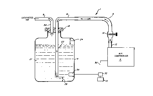
Figure 1 illustrates an air-moisture generation system of
the present invention.
DETAILED DESCRIPTION
Figure 1 indicates generally the inhalation system 1. The
system comprises an air compressor 2 which may simply be of the
fish tank type. The compressor is coupled to a liquid reservoir
provided by the tank 4 by means of the air inlet line 6. The
tank ~ may simply be a 2-quart container ar larger, preferably
made of plastic. Leading from the tank is the air outlet line 8.

M0330/7003 -3-
A power supply l0 is provided to enable operation of the air
compressor 2. The air compressor normally is provided with an
outlet conduit 12 to which a metering~valve 14 is coupled. This
metering valve essentially forms a metering jet having a fixed
orifice on the order of 0.050-0.060-inch. It has been found that
maximum moisture vapor can be created with a relatively small size
of metering jet. The metering valve is such as to control to a
desired size a restricted opening in the inlet line 6. The size
of this restriction is chosen so as to enable reasonable control
of pressure and volume of the air flowing in line 6 to enable a
desired output to be obtained from the tank 4.. The outlet line 6
can of course be of any length and usually is made of plastic
material, and terminates in a connection with a rigid tube 16.
The tube 16 is passed through an opening in a stopper 18 mounted
on the tank 4 and extends into the tank in a straight section 20,
which terminates at a distance 26 from the,.bottom of the tank.
The body of the liquid 22 is such that it does not fill the entire
tank and leaves an air space 24...above.the liquid 22 to provide a
storage space for saturated air. The outlet line 8 can also be
of any desired length and it terminates in a neck 28 which also
passes through the stopper 18 and extends into the air space
above the body of liquid.
The device as described is very simple in construction,
requiring readily available components. It can be used for a
number of purposes such as simply providing a stream of saturated

~~~~~2a
M0330/7003 -4-
air for humidifying air space. In such case the liquid employed
may be distilled water so as to avoid deposition of powder
residue on adjacent surfaces. ~ .
Alternatively, the system may be employed in inhalation
therapy wherein the liquid 22 in the tank can be mixed with
medication to treat lung infections. Still further, the system
may be used as a deodorizer and accordingly, scented liquid may
be employed in the tank 4.
Where it is desired to prevent continuous operation of the
air compressor when the liquid is exhausted in the tank 4, there
may be provided a float switch 34 which is so located within the
tank 4 in relation to the outlet of the straight section 20 of
inlet line 6, that when the liquid level drops below a designated
point. a signal is created to actuate another switch 32, which
normally is closed, arid place it in an open circuit position.
Accordingly, power will be.disrupted in-power line 30 to the
compressor and it will be shutoff. Conversely, when the tank 4
is again filled with liquid, the gYoat switch 34 will operate so
as. to again close switch 32 and allow the compressor to function.
While a specific embodiment has been shown and described,
many variations are indeed possible. Various shaped tanks may be
provided and various dimensional changes may be made in order to
accommodate the system to any desired configuration.

Representative Drawing
A single figure which represents the drawing illustrating the invention.
Administrative Status

2024-08-01:As part of the Next Generation Patents (NGP) transition, the Canadian Patents Database (CPD) now contains a more detailed Event History, which replicates the Event Log of our new back-office solution.

Please note that "Inactive:" events refers to events no longer in use in our new back-office solution.

For a clearer understanding of the status of the application/patent presented on this page, the site Disclaimer , as well as the definitions for Patent , Event History , Maintenance Fee  and Payment History  should be consulted.

Event History

Description Date
Time Limit for Reversal Expired 2008-09-17
Letter Sent 2007-09-17
Inactive: Late MF processed 2006-10-02
Letter Sent 2006-09-18
Inactive: IPC from MCD 2006-03-11
Inactive: Entity size changed 2003-09-18
Grant by Issuance 2000-12-19
Inactive: Cover page published 2000-12-18
Pre-grant 2000-09-11
Inactive: Final fee received 2000-09-11
Letter Sent 2000-07-12
Notice of Allowance is Issued 2000-07-12
Inactive: Approved for allowance (AFA) 2000-06-20
Amendment Received - Voluntary Amendment 2000-03-24
Inactive: S.30(2) Rules - Examiner requisition 1999-12-14
Inactive: RFE acknowledged - Prior art enquiry 1997-10-08
Inactive: Application prosecuted on TS as of Log entry date 1997-10-01
Inactive: Status info is complete as of Log entry date 1997-10-01
All Requirements for Examination Determined Compliant 1997-07-16
Request for Examination Requirements Determined Compliant 1997-07-16
Application Published (Open to Public Inspection) 1991-11-05

Abandonment History

There is no abandonment history.

Maintenance Fee

The last payment was received on 2000-09-01

Note : If the full payment has not been received on or before the date indicated, a further fee may be required which may be one of the following

  • the reinstatement fee;
  • the late payment fee; or
  • additional fee to reverse deemed expiry.

Please refer to the CIPO Patent Fees web page to see all current fee amounts.

Fee History

Fee Type Anniversary Year Due Date Paid Date
Request for examination - small 1997-07-16
MF (application, 7th anniv.) - small 07 1997-09-17 1997-08-22
MF (application, 8th anniv.) - small 08 1998-09-17 1998-08-18
MF (application, 9th anniv.) - small 09 1999-09-17 1999-09-01
MF (application, 10th anniv.) - small 10 2000-09-18 2000-09-01
Final fee - small 2000-09-11
MF (patent, 11th anniv.) - small 2001-09-17 2001-08-21
MF (patent, 12th anniv.) - small 2002-09-17 2002-08-23
MF (patent, 13th anniv.) - standard 2003-09-17 2003-09-03
MF (patent, 14th anniv.) - standard 2004-09-17 2004-09-01
MF (patent, 15th anniv.) - standard 2005-09-19 2005-09-01
MF (patent, 16th anniv.) - standard 2006-09-18 2006-10-02
Reversal of deemed expiry 2006-09-18 2006-10-02
Owners on Record

Note: Records showing the ownership history in alphabetical order.

Current Owners on Record
CALVIN KALISHMAN
Past Owners on Record
None
Past Owners that do not appear in the "Owners on Record" listing will appear in other documentation within the application.
Documents

To view selected files, please enter reCAPTCHA code :


To view images, click a link in the Document Description column. To download the documents, select one or more checkboxes in the first column and then click the "Download Selected in PDF format (Zip Archive)" or the "Download Selected as Single PDF" button.

List of published and non-published patent-specific documents on the CPD .

If you have any difficulty accessing content, you can call the Client Service Centre at 1-866-997-1936 or send them an e-mail at CIPO Client Service Centre.


Document
Description 
Date
(yyyy-mm-dd) 
Number of pages   Size of Image (KB) 
Abstract 1993-12-14 1 15
Cover Page 1993-12-14 1 11
Claims 1993-12-14 2 36
Drawings 1993-12-14 1 16
Description 1993-12-14 4 109
Claims 2000-03-24 2 74
Cover Page 2000-11-16 1 31
Representative drawing 1998-06-25 1 11
Representative drawing 2000-11-16 1 7
Acknowledgement of Request for Examination 1997-10-08 1 173
Commissioner's Notice - Application Found Allowable 2000-07-12 1 162
Maintenance Fee Notice 2006-10-16 1 173
Late Payment Acknowledgement 2006-10-16 1 166
Maintenance Fee Notice 2007-10-29 1 171
Correspondence 2000-09-11 1 49
Fees 1996-08-20 1 52
Fees 1995-08-30 1 60
Fees 1994-09-08 1 62
Fees 1993-08-19 1 36
Fees 1992-08-19 1 32