Note: Descriptions are shown in the official language in which they were submitted.
3'~
Method and Apparatus
This invention relates to a method and apparatus for
introducing into a container a material to be dispensed in
aerosol form and a propellant therefor. The invention is
particularly concerned with the introduction of pharmaceutical
materials into containers, and the following description
concentrates on this. xt is to be understood, however, that the
invention can also be applied to other materials.
Conventionally, pharmaceutical materials which are to be
dispensed in aerosol form are usually suspended in a mixture of
at least two propellants, at least one of which has a high
enough boiling point to be liquid at room temperature, and at
least one of which has a low enough boiling point to be a gas
at room temperature.
For convenience, these are referred to below as a liquid,
or low pressure, propellant, and a gaseous, or high pressure,
propellant respectively. The pharmaceutical material is first '
suspended in the liquid propellant by a mixing operation. Each
aerosol container is then partly filled with this suspension.
A quantity of the gaseous propellant is then introduced into
each of the containers using either a cold-fill method or a
high-pressure method. In the former, the filling operation is
carried out at a temperature sufficiently below room
temperature for the gaseous propellant to be liquid. Each
container is then closed by a closure which includes an outlet
"\
2
valve through which the contents of the container can
subsequently be dispensed) In the high-pressure method, the
closure is applied to the container before the gaseous
propellant is introduced, and that propellant is introduced
subsequently into each container by forcing it under pressure
into the container through the outlet valve, which during this
operation acts in effect as an inlet valve.
No satisfactory method currently exists for filling a
container with a suspension or solution of a pharmaceutical in
a single or mufti-component propellant which is gaseous ati.room
temperature. It is an object of one aspect of the present
invention to provide such a method, and to provide an apparatus
for carrying out that method.
Figures 1 and 2 of the accompanying drawings show
diagrammatically a typical known apparatus for introducing into
a container a pharmaceutical material arid a two-component
propellant system.
Figure 1 shows the introduction into a container C of a
suspension of a pharmaceutical material in a liquid propellant.
Vessel 1 contains a bulk supply of this suspension which is
pumped by a pump 2, through a non-return valve 3, into a
metering cylinder 4 provided with a vent 5. From there, the
suspension passes to a filling head 8. In the inoperative
condition the suspension passes through the head 8 to a non-
return valve 9 and thence back to the vessel. The suspension
is thus kept constantly in circulation. When a quantity of
suspension is to be introduced into the container C, the
container is positioned below the head 8, and the valves 3 and
3
9 are closed. The pneumatic cylinder 6 is then operated to
force the piston therein downwardly, thus increasing the
pressure in the suspension trapped between the valves 3 and 9
to a level sufficiently to open a valve in filling head 8 and
to cause suspension to pass from the filling head into the
container C. The valves 3 and 9 are then opened and the valve
in filling head 8 shut, and when the piston in the cylinder &
is withdrawn to its original position the cylinder 4 refills
from the vessel 1. Movement of the filling nozzle into and out
of engagement with each can is effected by a piston and
cylinder arrangement 7. The filling head 8 is arranged to
operate only when it is in engagement with a container C.
The apparatus of Figure 1 introduces into container C a
suspension of pharmaceutical material in a liquid propellant,
and after an aerosol valve is crimped on the can C the
apparatus shown in Figure 2 opexates on it to introduce gaseous
propellant. The apparatus of Figure 2 is formed of components
which are substantially the same in principle as corresponding
components of Figure 1, except that there is nothing
corresponding to the non-return valve 9 and there is no
recycling. Components in Figure 2 are denoted by reference
numerals which correspond to those used in Figure 1, with the
addition of 10. The vessel 11 contains gaseous propellant only,
under sufficient pressure for it to be a liquid, and contains
no pharmaceutical material.
When the apparatus of Figure 2 is in operation, a small
quantity of gaseous propellant escapes each time the filling
head 18 is lifted from a container C. This is of no particular
\.
4
~0~~"~~
consequence provided the amount of propellant lost in this way
is small.
However, this feature of the operation of the apparatus of
Figure 2 means that were it used for introducing into a
container a suspension or solution of a pharmaceutical material
in a high pressure propellant, it would be entirely
unsatisfactory. It can be seen that if vessel 11 contained
such a suspension or solution, what would escape each time the
filling head Z8 was lifted from a container would be a quantity
of such a suspension or solution. This would present a hazard
to workers involved in the operation, and where the
pharmaceutical material concerned was an expensive one, could
also represent a significant financial loss. Furthermore, the
escaped pharmaceutical material would tend to deposit on the
surrounding part of the apparatus and on the exterior of the
container itself, giving rise to problems of cleaning. The
first of these problems could be avoided, in theory, by
surrounding the apparatus of Figure 2 by an exhaust system,
though this would involve considerable expense. The other two
problems would not be avoided even by such an exhaust system.
According to the present invention there is provided a
method of introducing into a container a suspension or solution
of a material in a propellant held under pressure, which
comprises bringing a filling head into communication with the
container; introducing a quantity of such suspension or
solution into tha container through the filling head
introducing a quantity of high pressure propellant without any
of the said material into the filling head while it is still in
' ~ CA 02025779 1999-03-03
communication with the container, thereby to flush
through any suspension or solution remaining in the
filling head; and withdrawing the filling head from the
container.
5 According to the present inventlOIl there is further
provided an apparatus for introducing into a container a
suspension or solution of a material in a propellant held
under pressure, which comprises a filling head adapted to
be brought into and out of communication with the
container, means for supplying to the filling head a
quantity of the said suspension or solution; and means
for supplying to the filling head qnamtity c>f high
pressure propellant without any of the said material, the
filling head being so arranged that the flow of
propellant without any of the said material flushes out
any suspension or solution remaining in the filling head.
The invention also provides for the apparatus noted
above wherein the filling head also comprises a passage
for the suspension or solution and for the propellant
alone, an inlet for the suspension or solution ane~ an
inlet for the propellant alone, each inlet c:on~rnunicating
with the said passage, and a valve member movable between
a position closing the inlet for the suspension or
solution and a position closing the inlet for the
propellant alone, whereby at any one time only one of the
said inlets is communicating with the sari passage.
The invention also provides for the apparatus noted
above wherein the filling head also comprises a passage
for the suspension or solution and for the propellant
alone, an inlet for the suspension or solution and an
inlet for the propellant alone, each inlet communicating
with the said passage, and a value member in each inlet,
the inlets being opposite one anther dnd the valve
CA 02025779 1999-03-03
Sa
members being arranged so that when one is open it
presses the other further into its closed position.
The invention also provides a filling head for use
in introducing into a container a suspension or solution
S of a material in a propellant held under pressure,
comprising an outlet adapted to communicate, in use, with
the container, first and second inlets eac_:h communicating
with the said outlet via a common flc_~w path, through
which inlets, in use, propellant containing the said
material, and high pressure propellant not containing the
said material, are respectively introduced; anc-~ means for
selectively closing the first and secom~ inlets so that
fluid entering either inlet cannot flow out of the other.
In all aspects of the invention, it is ae~vantageous
and convenient if the propellant without the suspension
or solution is the same propellant as
that in which the material is held.
6
Advantageously, the propellant is 1,1,1,2-tetrafluoroethane
(also known as propellant "134a").
Preferably, the material being filled into the container
is a pharmaceutical substance, for example salbutamol or
beclomethasone dipropionate.
Preferred embodiments ef the invention are described
below, by example only, with reference to Figures 3, 4A-4D and
5 of the accompanying drawings, in whichs
Figure 3 shows diagrammatically the apparatus of the
present invention; ;..
Figures 4A-4D show one embodiment of a filling head which
may be used in the apparatus of Figure 3; and
Figure 5 show another embodiment of a filling head which
may be used in the apparatus of Figure 3.
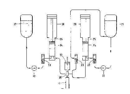
The apparatus according to the invention shown in Figure 3
comprises, in effect, something resembling a combination of the
apparatus of Figures land 2, but with a common filling head of
a novel design. The components shown in Figure 3 are denoted
by reference numerals which correspond to those shown in Figure
1, but with the addition of 20 or 30. The vessel 21 contains a
suspension of a pharmaceutical material in a high-pressure
propellant, and the vessel 31 contains a supply of the same
propellant alone, i.e. without any pharmaceutical material
suspended therein. Although the vessel 31 here contains the
same propellant, a different high pressure propellant can of
course be used. Furthermore, vessel 21 might contain a
solution of the pharmaceutical material, instead of a
suspension.
7
Figures 4A-4D show in more detail, arid on a larger scale,
the filling head 28 used in the apparatus of Figure 3. The
head comprises a substantially cylindrical body 40, the lower
end of which is adapted, in use, to engage over the upper end
of an aerosol container C. A tubular member 43 is mounted for
slidable movement within. tha body 40. The tubular member 43
has a caide base portion 44, a narrower body portion 45 and a
still narrower neck portion 46. In this context, "wide" and
"narrow" refer to diameters.
The nick portion 46 of the tubular member 43 penetrates
the base of an inverted cup 47, the wall of which surrounds the
body portion 45. The body portion 45 can thus slide into the
cup 47.
The base portion 44 of the tubular member abuts an
inwardly extending lip 50 of the body 40. An outwardly
extending lip 51 of the cup 47 rests on an internal shoulder 52
of the body 40.
A tubular pillar 55 is threadedly engaged with the body 40
such that its lower edge engages on the lip 51 of the cup 47.
The pillar 55 thus fits around the wall of the cup 47.
A ring 56 is screwed into the pillar 55 so that it is
mounted above the cup 47. The neck portion 46 of the tubular
member 43 just enters into the ring 56. A sliding seal 58 is
fitted between the ring 56 and the neck portion 46. Rubber O
ring seals 59, 60 are also provided between the ring 56 and the
pillar 55 and in the base portion 44 of the member 43, where
the nozzle of the container C fits (see later).
The ring 56 defines an upwardly tapering seat 62 for a
~~~~"l'~~~
correspondingly shaped plug 63. The plug 63 is biassed into
the seat by a compression spring 64, the upper end of which
acts against an inwardly directed lip 65 of the pillar 55.
Above the lip 65 are opposed inlets 69,70 connecting from
the exterior with the interior of the pillar 55, and thus with
tre interior of the tubular member 43, and sa to the~.container.
Inlet pipes 72,73 are fitted into the inlets 69,70
respectively, sealed therein by 0-ring seals 74,74'.
Between the inlets is provided a ball-bearing 75 which can
close against either 0-ring seal 74, 74' ~:o form a valve. As
explained below, the ball bearing 75 is either forced against
the O-ring 74 to seal the inlet 69 or against the O-ring 74' to
seal the inlet 70.
Above the inlets 69,70, the pillar 55 provides a circular
seat for a piston (not shown) which acts to press the fitting
head down onto the container C.
The inlet 69 is connected to the line which carries the
suspension from the metering cylinder 24 to the non-return
valve 29. The inlet 70 is connected to the outlet of the
metering cylinder 34 which contains propellant.
In its rest state, suspension S flows along the line from
the metering cylinder 24 to the non-return valve 29 without
entering the intarior of the pillar 55, being prevented from
doing so by the ball bearing valve 75, forced against the 0-
ring 74 by the over-pressure of propellant P in the line from
cylinder 34. When it is desired to introduce a quantity of
suspension into the container through the head 28, as described
immediately below, the valves 23 and 29 are closed and the
CA 02025779 1999-03-03
9
cylinder 26 operated to cause the piston therein tee move
downwardl y .
At this stage the filling head 28 has been moved
downwards, onto container C, as shown in Figure 4B. The
nozzle of the container rests against 0-ring seal 60 and,
as the head is lowered, the nozzle forces the tubular
member 43 into the cup 47 and ring 56 until the lip 50 of
the body 40 abuts the rim of the container. In this
position, the neck portion 46 of the tubular member 43 has
penetrated through the ring 56 and pushes the plug 63 out
of the seat 62, against the action of the spring 64, with
as seen in Figure 4(b), the interiors of the pillar 55 and
the tubular member 43 providing a passage to the
container. Communication between the interior of the
pillar 55 and the interior of the tubular member 43 is now
possible.
The increase in pressure of the suspension in the
metering cylinder 24 which is caused by the operation of
cylinder 26 is sufficient to overcome the force of the
propellant on the ball bearing valve 75 and suspension is
thus able to flow from the inlet 69, through the passage
formed in the interior of the pillar 55 am_~ the tubular
member 43, aTld into the container. The inlet 70 remains
closed since the pressure of the suspension fc_srces the
ball bearing valve 75 against 0-ring 74'. Thus,
suspension is unable to pass from the inlet 69 to the
inlet 70 and contaminate the inlet 70.
The next stage in the filling of the corutainer is to
pass a quantity of propellant without any pharmaceutical
material suspended therein into the head 28, ttnrough the
passage formed in the interior of the pillar 55 arid of the
tubular member 43, and thence into the container. This is
done by closing the valve 33 and operating
~i~~~°~~~~
the pneumatic cylinder 36. The increase in the pressure of the
propellant which this causes is sufficient to move the ball
bearing valve 75. Propellant is unable to pass from the now
open inlet 70 to the inlet 69 because of the ball bearing valve
5 75 which is forced against 0-ring 74. This position is shown
in Figure 4C.
Introducing propellant through the inlet 70 while the head
28 is still on container C flushes out suspension remaining in
the interior of the pillar 55 and the tubular member 43.
~~ 10 Accordingly, when the head 28 is lifted from the aerosol
container after the filling operation has been completed, as
shown in Figure 4D, such material as escapes from the lower end
of the head consists substantially entirely of propellant, and
no pharmaceutical material escapes into the surrounding
atmosphere.
Figure 5 shows an alternative embodiment of a filling head
28 to be used in the apparatus of Figure 3. The head shown in
Figure 5 comprises a substantially cylindrical body 80, the
lower end of which is adapted, in use, to engage over the upper
end of an aerosol container (not shown in this figure). A ring
81 is mounted far longitudinal sliding movement within the body
80 and has an inwardly directed flange 82 on which rests the
lower end of a tubular member 83. The upper portion of the
tubular member 83 is surrounded by an inverted cup 84. The cup
84 is in turn surrounded by the annular lower portion of a
pillar 85. The annular portion is screw threaded into the body
80 to retain the cup 84 in place and sealing is provided by an
O-ring seals 86 and a sliding seal 87. The tubular member 83
11
is urged into engagement with the flange 82 by a compression
spring 88, the upper end of which bears against a face of the
cup 84.
The pillar 85 has a pair of opposed inlets 89 and 90. fihe
inlet 89 is connected to the line which carries suspension from
the watering cylinder 24 to the non-return valve 29. The inlet
90 is connected to the outlet of the metering cylinder 34 which
contains propellant. The inlets 89 and 90 communicate with the
interior of the tubular member 83 via respective poppet valves
91 and 92 which are biassed by compression springs 93 and 94
into their closed positions.
As in the embodiment of Figure 4, in its rest state,
suspension flows along the line from the metering cylinder 24
to the non-return valve 29 without entering the interior of the
tubular member 83, being prevented from doing so by the valve
91. When it is desired to introduce a quantity of suspension
into the container through the head 28 the valves 23 and 29 are
closed, and the cylinder 26 operated to cause the piston
therein to move downwardly. The increase in pressure in the
suspension in the metering cylinder 24 which is caused by this
is sufficient to overcome the force of the spring 93 balding
the valve 91 shut, and suspension is thus able to flow from the
inlet 89, through the interior of the tubular member 83, into
the container. The valve 92 remains closed, and indeed the
effectiveness of the seal which it provides is increased by the
head 95 of the valve 91 engaging the head 96 of the valve 92.
Thus, suspension is unable to pass from the inlet 89 to the
inlet 90 and contaminate the inlet 90.
~~~f~r~~)
12
The next stage in the filling of the container, as in the
previous embodiment, is to pass a duantity of propellant
without any pharmaceutical material suspended therein into the
head 28, through the tubular member 83, and thence into the
container. This is done by closing the valve 33 and operating
the pneumatic cylinder 36. The increase in the pressure of the
propellant which this causes is sufficient to open the valve 92
to permit propellant through the head 28. Propellant is unable
to pass from the inlet 90 to the inlet 89 because of the action
of the valve 91. ;~.
Introducing prapellant through the inlet 90 while the head
28 is still on the container flushes suspension remaining in
the interior of the tubular member 83 and in the space
immediately above the tubular member. Accordingly, this
embodiment also provides that when the head 28 is lifted from
the aerosol container after the filling operation has been
completed, such material as escapes from the lower end of the
head consists substantially entirely of propellant, and no
pharmaceutical material escapes.