Note: Descriptions are shown in the official language in which they were submitted.
~642~
IMPROVED FIBER PAYOUT M~r~TN~
BACKGROUND OF THE lN V~l. ~ lON
Field of the Invention:
The present invention relates to optical fiber
technology. More specifically, the present invention
relates to techniques for high speed payout of optical
fiber.
While the present invention is described herein with
reference to illustrative embodiments for particular
applications, it should be understood that the invention
is not limited thereto. Those having ordinary skill in
the art and access to the teachings provided herein will
recognize additional modifications, applications, and
embodiments within the scope thereof and additional
fields in which the present invention would be of
significant utility.
Description of the Related Art:
optical guidance of high speed vehicles involves a
payout of optical fiber under conditions which place
considerable stress on the fiber. Hence, numerous
techniques have been developed to test the ability of the
fiber to withstand such stress. Ideally, the test
provides an accurate simulation of the stress condition
on the fiber in a real application.
For example, a payout test has been developed for
ground launched optically guided vehicles which involves
7~
2 ~26~28
-
the high speed payout of optical fiber from a bobbin into
the air. A signal is transmitted over the fiber and the
desired test measurements are made. Unfortunately, it
has been discovered that as the fiber exits the payout
machine, it travels 20 to 50 feet in a straight line
before aerodynamic forces cause it to stop almost
instantly in mid-air. This causes a snarl of fiber to
form in the air before falling to the ground. The
numerous sharp bends induced in the fiber cause signal
attenuation and prevent vehicle control signals from
being transmitted over the fiber. This undesirable
"bird nesting" of the fiber has been observed to affect
signal transmission at payout velocities exceeding 400
feet per second.
Thus, there is a need in the art to provide an
improvement in the high speed payout of optical fiber
from a stationary payout machine.
SUMMARY OF THE lNv~NllON
The need in the art is addressed by the present
invention. The invention is adapted for use with a
payout machine having a payout wheel for pulling optical
fiber from a bobbin and dispensing it into the air. The
invention provides a method and apparatus for deflecting
the fiber into a helical pattern as the fiber is payed
out from the payout wheel. The invention includes a
deflector mounted in the path of the fiber which is
rotated as the fiber is payed out to generate the helical
payout pattern.
In a specific embodiment, the deflector includes a
hollow shaft through which the fiber passes as it being
payed out from the payout wheel. The hollow shaft
2026428
S includes a tunnel along the length thereof. The tunnel
has a first portion which directs the fiber along the
longitudinal axis of the shaft, and a second portion at
an angle with respect to the first portion. The
spreading of the fiber by the rotating deflector
mitigates signal attenuation.
Ideally, the rate of rotation of the deflector is
matched to the rate at which fiber is pulled from the
bobbin. The direction of rotation of the deflector is
opposite to the direction at which fiber is pulled off
the bobbin. This effectively cancels the twist induced
in the fiber during payout from the bobbin and further
reduces sharp bends or "pigtails" in the fiber.
Other aspects of this invention are as follows
In a payout machine having a payout wheel for
pulling helically wound optical fiber axially from a
bobbin to impart to said fiber twist in a first
direction as said fiber is dispensed into the air, the
improvement comprising:
means for deflecting said fiber into a helical
pattern as said fiber is paid out from said payout
wheel, said means including a deflector mounted in the
path of the fiber and rotatable about an axis to impart
an opposite twist to the fibre.
An improved payout machine for paying out helically
wound optical fiber from a bobbin, including:
- a payout wheel for pulling said fiber axially from
said bobbin to impart to said fiber twist in a first
direction;
a deflector mounted in the path of the fiber for
deflecting said fiber as it is being paid out from said
payout wheel; and
means rotatable about an axis to payout said fiber
in a helical pattern having opposite twist.
An improved payout machine for paying out optical
fiber from a bobbin, including:
2o26~28
a payout wheel for pulling fiber from said bobbin;
a deflector mounted in the path of the fiber for
deflecting said fiber as it is being paid out from said
payout wheel; and
means for rotating said deflector,
said deflector including a plate which flexes in
response to such rotation to payout said fiber in a
helical pattern.
A method for paying out helically wound fiber
including the steps of:
axially pulling fiber from a bobbin to impart to
said fiber twist in a first direction;
passing the fiber through a deflector; and
rotating the deflector about an axis to payout said
fiber in a helical pattern having opposite twist.
BRIEF DE8CRIPTION OF THE DRAWING8
Fig. 1 is a diagram of the fiber payout machine of
the present invention.
Fig. 2 is a sectional view of an illustrative
implementation of the deflector.
Fig. 3(a) shows a plan view of an alternative
preferred embodiment of the deflector utilized in the
payout machine of the present invention.
Fig. 3(b) is a top view of the alternative
preferred embodiment of the deflector utilized in the
payout machine of the present invention.
Fig. 3(c) is a side view, partially in section, of
the alternative preferred embodiment of the deflector
utilized in the payout machine of the present invention.
Figs. 4(a) and 4(b) show a sectional view of an
alternative implementation of the fiber payout machine
of the present invention. Fig. 4(a) is a sectional view
of a portion of Fig. 4(b).
~.
2026i~
DE8CRIPTION OF THE INVENTION
Illustrative embodiments and exemplary applications
will now be described with reference to the accompanying
drawings to disclose the advantageous teachings of the
present invention.
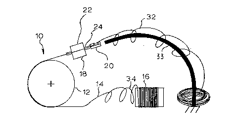
Fig. 1 is a diagram of the improved fiber payout
machine 10 of the present invention. The machine 10
includes a conventional (pneumatic shoe) payout wheel 12
which pulls optical fiber 14 off a bobbin 16 and
dispenses it into the air. A particularly novel feature
of the invention is the provision of a motorized
deflector 18 which includes a deflector 20 and a motor
22. The motor 22 drives the deflector 20 so that the
fiber 14 is payed out in a helical pattern 32. As shown
in Fig. 1, an optional bent rod 33 which may be used to
collect the fiber 14 as it is being payed out. The bent
rod 33 is positioned to lie in the axis of the payout
helix 32 and collects the fiber in circles on the
ground. This is a convenient way of collecting the
fiber but is not required for operation of the
deflector.
The motor 22 is shown as a hollow shaft motor
although those skilled in the art will appreciate that
other motor arrangements may be used to provide
rotational drive of the deflector 20. One such
alternative is to use a belt driven spindle such as is
used in a tool post grinder. A working model was built
utilizing a spindle from a Thermac~ model no. J-2A
grinder.
The illustrative implementation of the deflector 20
is shown in the sectional view of Fig. 2. As shown in
Fig. 2, the deflector 20 is adapted for insertion over
the hollow shaft 24 of the motor 22. The deflector 20
may be constructed of hard anodized aluminum for good
wear characteristics and teflon coated for low friction.
A tunnel 26 is provided in the deflector 20. The tunnel
6
26 includes a first section 28 which directs the fiber
onto a longitudinal axis 29 of the motor shaft 24. The
tunnel 26 includes a second section 30 which has a
deflector with a large radius to gently change the
direction of the fiber 14 through an angle .THETA.. The
deflector angle .THETA. is selected to provide the proper
diameter helix based on fiber velocity and deflector
rotational velocity.
In the illustrative embodiment, a 10 degree angle
was chosen to provide the required helix diameter. In
the preferred embodiment, the deflector angle .THETA. and the
rotational velocity are chose so that the mean radius
of the payout helix 32 is equal to that of the payin
helix 34.
Fig. 3(a) shows a preferred alternative embodiment
of the deflector 20. For this embodiment, the deflector
20 is designed to fit inside a hollow shaft 24. The
hollow shaft 24 would replace the motor shaft 24 of the
motor 22 or the spindle shaft as described above. The
deflector of Fig. 3(a) has a tunnel 26 with the first
and second sections 28 and 30, respectively, as
mentioned above. Section 28 incorporates a ramp to
direct the fiber onto the hollow shaft centerline.
Section 30 incorporates a circular radius deflector to
redirect the fiber. The deflector 20 may be secured to
the shaft 24 by pinning or any conventional keying
device. Shaft 24 may be rotated as part of a motor or
may be belt driven by a motor (not shown). Figures 3(b)
and 3(c) detail the deflector 20 which is inserted into
hollow shaft 24 during operation.
Fig. 3(b) is a top view of the deflector 20 of Fig.
3(a) and Fig. 3(c) is a side view, partially in section,
of same. As shown more clearly in Figs. 3(b) and 3(c),
the first section 28 is a long straight ramp designed to
bring the fiber 14 to the shaft centre line in a very
gradual manner. The second section 30 is a circular
202~2~
6a
curve to gently change the angle of the fiber 14. By
gently changing the angle of the fiber 14, stress due to
deflection is minimized. The ramped first section 28 is
substantially disposed within a small diameter first
portion 32 of the deflector 20, while the second section
30 thereof is disposed in a larger diameter second
portion 34. The small diameter cross-section of the
first portion 32 allows for insertion into the hollow
motor shaft 24. The larger diameter portion 34 extends
beyond the hollow shaft and provides an exit for the
deflected fiber.
In operation, the fiber 14 is fed from the bobbin
16 through the payout wheel 12 and the deflector 20.
Then, the payout wheel 12 is activated and the motor 22
for the deflector 20 is activated. Activation of the
motor 22 causes the deflector 20 to rotate about the
longitudinal axis of the fiber 14. In the preferred
embodiment, the motor 22 is designed so that the
rotational rate of the deflector matches the rotational
rate of the fiber helix as it leaves the bobbin. For
example, a bobbin 16 having a six inch diameter yields
approximately 1.5' of fiber in each turn of the helix
24. Thus, the deflector should rotate one turn for
every 1.5' of fiber passing therethrough. Stated
alternatively, the rotational payout rate of the
deflector 20 should match the rotational helix payout
rate of the bobbin 16. In practice, the invention was
found to operate satisfactorily with a deflector payout
rotational payout rate within + 50% the helix rotational
rate.
Also, in the preferred embodiment, the direction of
rotation of the deflector is opposite to the direction
at which fiber is pulled off the bobbin. This
effectively cancels the twist induced in the fiber
during payout from the bobbin and further reduces sharp
bends or "pigtails" in the fiber.
2~26~ 2~
6b
Figs. 4(a) and 4(b) show an alternative embodiment
of the fiber payout machine 10' of the present
invention. The embodiment of Fig. 4(b) includes a
deflector assembly 20' driven by a belt 21' and motor
22'. The deflector assembly 20' is mounted on bearings
23'. The deflector assembly 20' includes a flexible
plate 40' which is biased by a pivotally mounted weight
42'. Prior to the activation of the motor 22', the
plate 40' is straight
7 2~2~42~
and the fiber 14' is easily inserted therethrough. When
the assembly 20' is spun up by the motor 22', centrifugal
forces cause the weight 42' to bear on the plate 40'.
This induces a deflection in the fiber 14' in the manner
S described above. In this embodiment, the degree of
deflection, that is, the size of the payout helix, may be
controlled by controlling the rate of rotation of the
assembly 20'.
Thus, the present invention has been described
herein with reference to a particular embodiment for a
particular application. Those having ordinary skill in
the art and access to the present teachings will
recognize additional modifications applications and
embodiments within the scope thereof.
It is therefore intended by the appended claims to
cover any and all such applications, modifications and
embodiments within the scope of the present invention.