Note: Descriptions are shown in the official language in which they were submitted.
~ J~3
P-474 DRD - 1 -
APPARATUS AND METHOD FOR
FORMING A DOOR PANEL BELT TRIM
TECHNICAL FIELD
This invention relates to appar~tus for
shaping thermoformable plastic panels and more
particularly to apparatus and methods for shaping a
belt trim portion of a plastic vehicle door panel.
BACKGROUND ART
USPN 4,839,118 discloses a glove
compartment box with a plastic rear wall portion
that has integral flanges thereon thermally formed
to fasten the rear wall with respect to the outer
shell of the glove box.
While suitable for its intended purpose,
the '118 patent does not address the problem of how
tn form a return flange at the belt trim support of
a vehicle door panel so as to avoid thermal stress
conditions in the vehicle door panel which will
cause it to be warped.
~ ~ ~ .t L ~ r ~
P-474 DRD - 2 -
One approach for forming vehicle door
panels with return bends on the belt trim support is
to provide an injection molding machine with dies
configured to have the return bend formed therein.
The return flange portion of the finished part
constitutes a die-locked feature which can only be
formed by use of retractable die members that add to
the cost of injection molding machines.
STATEMENT OF INVENTION AND ADVANTAGES
-
An object of the present invention is to
provide a vehicle door panel with a belt trim
portion thereon which is thermoformable to form a
return flange thereon without warping the panel.
Another object of the present invention is
to provide a vehicle door panel with a return flange
on the belt trim support thereof which is formed
without requiring special retractable injection mold
tooling for releasing a die locked return flange
from mold apparatus.
Yet another object of the invention is to
provide an improved method for forming a return
flange on the belt trim portion of a vehicle door
~3~ i3,l~
P-474 DRD - ~ -
panel ~hich includes the steps of locating the door
panel on a holding fixture to place the belt trim
portion for sequential clampingl backing, spot
heating and folding to form thP return flange
thereon.
Yet another feature of the present
invention is to provide a method for thermoforming
the belt trim portion of a vehicle door panel
including the steps of providing a door panel with a
thermoformable bent end having a corner, a distal
end and a smooth outer surface and an inner surface
having a notch along the width of the bent end for
defining a breakline for formation of a return
flange thereon; locating the door panel on a panel
fixture having locating pins thereon and a backing
member movable with respect to the fixture to be
selectively engageable with the bent end of a door
panel supported thereon; locating the door panel on
2Q the panel fixture to expose the bent end and the
notch therein at a point for heating and bending
with respect to the fixture; applying clamping
forces on the exterior of the corner and at the
inner surface of the heated bent end between the
corner of the bent end and the notch; applying heat
to the outer surface of the bent end at the notch at
P-474 DRD - 4 -
a rate to prevent thermal stress build-up in the
door panel which will cause the panel to warp;
thereafter applying clamping forces on the exterior
of the corner and at the inner surface of the heated
bent end between the corner of the bent end and the
notch; folding the heated bent end between the notch
and the distal end thereof to form a return flange
thereon bent reversely to the panel and at 90
degrees to the bent end; and cooling the bent end
and removing the clamping forces therefrom and
thereafter removing the shaped door panel from the
door holding fixture.
A further feature of the present invention
15 i5 to provide such a method further characterized by
applying the clamping force by providing a initial
back up force against the inner surface of the bent
end prior to application of the clamping force on
the exterior of the corner of the bent end.
Still another feature of the present
invention i5 to provide such a method further
characterized by folding the heated bent end by
directing a holding force against the outer surface
of the heated bent end and then pivoting the holding
force with respect to the heated bend end to cause
P-474 DRD - 5 -
the bend end to be formed against the holding
fixture from the notch to the distal end of the
heated bent end.
Still another feature of the invention is
to provide apparatus for practicing the method which
includes a door fixture means with a movable backing
member to back a belt trim portion when the panel is
clamped in place; a heater mechanism and a flange
former mechanism on the machine are sequentially
advanced with respect to the clamped door panel to
soften a thermoformable segment of the panel which
is then folded about the backup plate.
Yet another feature of the present
invention is to provide apparatus for shaping a
return flange on the bent end of a thermoformable
plastic vehicle door panel the apparatus including
door fixture means supported on a machine base and
including a movable backup member having a retracted
position and an extended position and positionable
in the retracted position when the bent end is
initially loaded on the door fixture means; the
apparatus further including clamp means for
2S selectively clamping and unclamping the bent end
when the door panel is supported on the door ~ixture
f~ ~J ~ .J `~
P-474 DRD - 6 -
means and means for spot heating the bent end when
the bent end is clamped to soften the thermoformable
material of the bent end without producing
differential thermal stresses in the vehicle door
panel capable of warping the panel; the apparatus
further including shaping means operable following
heating of the bent end to apply a force on the bent
end to form a reversely bent return flange thereon.
Other advantages, features and objects of
the present invention will be readily appreciated as
the same becomes more apparent by reference to the
following detailed description when considered in
conjunction with the accompanying drawings wherein:
BRIEF DESCRIPTION OF THE INVENTION
FIG. 1 is a fragmentary side elevational
view of apparatus in accordance with the present
invention showing the component parts thereof in
their home position;
FIGS. 2-4 are fragmentary side elevational
views of the apparatus of FIG. 1 showing the
2S component parts respectively in a clamping position;
a heatinq position and in a ~ending position;
2 ~ L/~
P-474 DRD - 7 -
FIG. 5 is a top elevational view of a
heating mechanism in the apparatus of FIG. 1;
FIG. 6 is a top elevational view of a
door panel support fixture in the apparatus of FIG.
l;
FIG. 7 is a fraymentary view of a flange
former prior to folding;
FIG. 8 is a fragmentary view of a flange
former following folding:
FIG. 9 is a perspective view of a vehicle
door panel prior to forming a reverse bend at the
belt trim surface thereof; and
FIG. 10 is a perspective view of a vehicle
door panel following formation of the reverse bend
thereon.
P-474 DRD - 8 -
DETAILED DESCRIPTION OF PREFERRED
EMBODIMENTS OF THE INVENTION
. _ . .
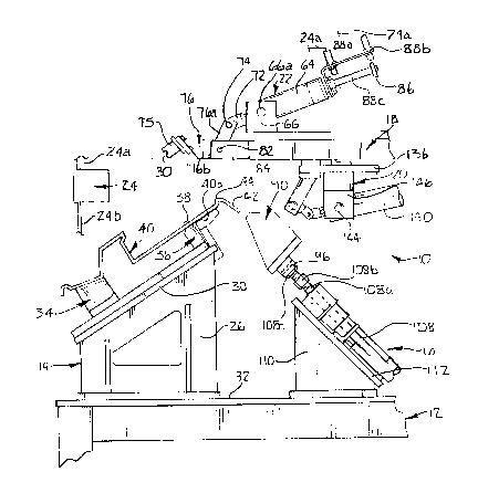
Figure 1 shows a machine apparatus 10
S having a base 12 with a door panel holding fixture
14 on one side thereof. A heating mechanism 16 is
supported on the other side of base 14. The machine
includes an overhead frame 18 carrying a flange
former mechanism 20 and a clamp meohanism 22. The
machine apparatus more particularly is operative
under the control of a controller 24 which receives
signals over lines 24a from suitable sensing m ans
such as limit switches (to be described~ and
operative to produce a plurality of control signals
on lines 24b that are operative to control the
operation of drive components (to be described).
Reerring now more particularly to Figures
1 and 6, the door panel holding fixture 14 is
illustrated as having a pair of trapezoidally
configured sides 26, 28 for supporting a platform 30
on an inclination with respect to the horizontal
surface 32 of the base. The degree of inclination
is slec~ed so that the operator loads door panels
2 ~ s~
P-474 DRD ~ 9 ~
into the machine apparatus 10 at approximately 30 .
This locates a belt trim portion of the door panel
at the top of the fixture 14.
More particularly, the fixture 14 includes
a lower support member 34 that is secured to the
platform 30 by suitable fastening means. An upper
support member 36 i5 connected to the upper end of
the platform 30. The upper support member 36 has a
pin 38 thereon that serves to locate the door panel
40 on the fixture 14 for subsequent formation of a
return flange thereon.
More specifically, referring now to Figure
9, a vehicle door panel 40 is illustrated that
includes a bent end 42 having a corner 44 thereon
and a surface portion 46 that defines a belt trim
support on the door panel 40 when the panel 40 is
assembled in a door assembly.
The panel 40 further includes a distal end
48 on the bent end 42 which, in accordance with the
present invention, will be shaped to form a return
flange 50 on a finished door panel as shown in
Figure 10.
P~474 DRD - 10 -
The inner surface 52 of the bent end 42
has a notch 54 formed therein along the width of the
bent end 42 of the panel 40.
In accordance with the present inve~tion,
the panel 40 is formed of a thermoformable material
such as ABS plastic, acrylic plastics, thermoplastic
olefins, nylon or rigged PVC.
In order to support the bent end 42 during
a thermo~orming process to be described, the door
panel holding fixture 40 includes a back-up
apparatus 56 which more particularly includ~s a pair
of spaced guide shafts 58, 60 supported for
reciprocal movement in spaced bearing blocks 58a,
58b and 60a, 60b, respectively. The shafts 58, 60
carry a baclcing plate 62 having a vertical portion
62a with a backing plate head 62b thereon with a
surface 62c which will shape the return flange 50
when it is formed on the bent end 42 in accordance
with the invention.
As shown in Figure 1, the backing plate 62
is in a retracted position where it will support the
panel 40 at the surface 40a thereon.
~, 2 ~
P-474 DRD - 11 -
In this posltion, the bent end 42 is
located at the top of the fixture 14 where it is
exposed for clamping and heating operations to be
described.
once the panel 40 is located on the
fixture 14, as shown in Figure 1, the clamp
mechanism 22 is operative to be moved into the
position shown in Figure 2 for holding the b~nt end
42 in a position for subsequent heating and forming
operations. In order to effectuate such clamping,
the clamping mechanism 22 more particularly includes
a power cylinder 64 that is pivotally connected to a
pair of spaced bearing blocks 66, 68 by a pair of
trunions 66a, 68a, respectively. The power cylinder
64 is a double acting air cylinder having a piston
rod 70 extending fro~ the lower end thereof. Rod 70
is connected to a knuckle 72 in turn pivotally
connected by a pivot pin 74 to one end 76a of a
clamp element 76 having the opposite end 76b thereof
connected to a tool 78 with a notched surface 80
thereon configured to supportingly receive the
corner 44 of the bent end 42.
2 ~ ~ :i9 si ~ l~
P-474 DRD - 12 -
The clamp element 76, more particularly,
is pivotally supported by a pivot pin 82 carried on
a bracket 84 on the overhead frame 18 to provide for
movement into a retracted home position 76c, shown
in broken outline in Figure 2, or into a clamping
position 76d, shown in solid line in Figure 2. The
operating position of the power cylinder 22 is
sensed when a collar 86 is moved with respect to
limit switch sensors 88a and 88b. The collar 86 is
supported on a rod extension 88c from the cylinder
22. The rod extension 88c will be positioned to
locate the collar 86 with respect to the limit
switch sensor 88a when the clamp mechanism 22 is in
its clamping position 76d and will be positioned
into alignment with the limit switch sensor 88b when
the clamp mechanism 22 is in its retracted position
76c. The respective limit switch signals will be
util~zed by controller 24 to initiate other machine
functions including heating and forming steps to be
described.
Referring now more specifically to the
heating mechanism 16, as shown in FIGS. 1 and 5, a
heater head 90 is connected to a pair of guide
shafts 92, 94 as best shown in Figure 5. The guide
shafts 92, 94 are supported for reciprocation with
respect to bearing blocks 92a, 92b and 94a, 94b,
~2;.~'~'fJ~
P-474 DRD - 13 -
respectively. The inboard ends 92c, 94c of the
guide shafts 92, 94 are connected to a plate 96
secured to the heater head 90. The opposite ends of
the guide shafts 92, 94 are connected to a plate 98
having a bumper 100 thereon selectively engageable
with a shock absorber mechanism 102 for controlling
movement of the head 90 when it reaches the heating
position shown in Figure 3.
The plate 98 carries an adjustable sensing
element 103 with respect to a limit switch sensor
104 to signal movement of the heater head 90 into
the heating position of Figure 3 to initiate a high
temperature output therefrom under the control of
the controller 24. More specifically, operation of
the heater head 90 into its heating position is
produced by a drive cyllnder 108 connected to a
heater platform 110 with an upper surface 112 formed
at an inclination with respect to the surface 32 of
the base 12. The drive cylinder 108 has a piston
rod 108a extending therefrom connec~ed by a coupling
108b to a threaded fitting 108c on the plate 96.
When the piston rod 108a is extended, the heater
head 90 will be located as shown in Figure 3 to
cause an infrared heater 114 therein to be located
in overlying relationship across the width of the
l, .2 ~ ~ ~ ~
P-474 DRD - 14 -
outer surface at a point overlying the notch 54 in
the bent end 42. More specifically, the infrared
heater 114 includes a quartz or pyrex tube 116 and a
resistance element 118 that is electrically
connected between terminals 120, 122 to a power
source 124 (FIG. 5) under the control of the
controller 24. The power source 124 is operative to
energize the résistance element 11~ at high and low
heat output states in response to signals from limit
switch sensors 104, 126.
When the heater head 90 is located in the
heat forming position of Figure 3, the resistance
element 118 is energized at the high temperature
level to spot heat the bent end 42 along a bend line
along the width thereof in a concentrated manner so
as to prevent excessive heating of the remainder of
the panel 40. The limit switch sensor 126 senses
retraction of the heater head 90 as sensor 126 moves
into proximity with an adjustable limit switch
element 128 on the plate 96. When retraction of the
heater head 90 is sensed, the controller 24 will
condition the power sources 124 to direct power to
the resistance wire 118 to maintain the heater in a
low en~rgy output state. When the heater head 90 is
retracted, the position will be held by a stop
P-474 DRD - 15 -
cylinder 130 on the platform 110 having a bumper
130a connected to a piston rod 130b of the stop
cylinder 130.
As shown in Figure 3, the clamp mechanism
22 is located to cause the fixturing tool 78 to be
clamped against the corner 44 of the bent end 42.
During the heating mode shown in Figure 3, the
flange former mechanism 20 is located in its home
position by a power cylinder 132. Following the
heating step, the flange former mechanism 20 is
actuated by the cylinder 132 ~o move on guide shafts
134, one of which is shown in Figure 3. The
platform 136 of the former 20 is supported on the
guide shafts 134 by bearing blocks, one of which is
shown at 138 in Figure 3. The flange former
mechanism 20 includes a second air cylinder 140
having its head 142 pivotally connected by a trunion
144 to a pair of support blocks 146 on the underside
of the platform 136. The power cylinder 140 has a
piston rod 148 (shown extended in Fig. 4) connected
to a knuckle 150 that in turn i5 pivotally connected
by a pin 152 to a forming bar 154. Forming bar 154
has a surface 156 thereon engageable with the outer
surfacP 46 of the vehicle door panel 40, as shown in
FIG. 7. The end 158 of the forming bar 154 is
r~ ,J
P-474 DRD - 16 -
located closely adjacent the notch s4 when the slide
cylinder 132 moves the bending bar 154 into initial
engagement with the bent end 42, as shown in FIG. 7.
Once the forming bar 154 is in engagement with the
bent end 42, the piston rod 148 is extended from
cylinder 140 to cause the forming bar 154 to rotate
along the path 159 downwardly from the position
shown in broken line in FIG. 4 to the solid line
position shown in FIG. 4. This causes the bent end
42 to fold from the notch 54 to the distal end 48
thereof downwardly against the surface 62c of the
backing plate head 62b so as to form the resultant
return bend 50 on the panel 40. Air jets 160 (F~G.
4) are then turned on to cool the thermoformed end
of the panel 40. The clamp mechanism 22 is then
retracted into its home position shown in Figure 1.
The backup apparatus 56 is retracted to enable the
finished part to be removed from the door panel
holding fixture 14.
INDUSTRIAL APPLICABILITY
While the illustrated apparatus and method
are shown with reference to a door panel having a
belt trim support thereon with a 90 return flange,
it will be appreciated that the apparatus and method
r i~
P-474 DRD - 17 -
are equally suited for forming 90 return bends on
other panels, such as shower or bath panels for use
in the plumbing industry, covers or container panels
for use in the packaging or the luggage industry, or
for use in other panel structures used in both auto
vehicle interior trim products and auto vehicle
exterior trim products.
The invention herein has been described in
an illustrative manner and it is understood that the
terminology which has been used it intended to be in
the nature of words of description rather than of
limitation. Obviously, many modifications and
variations of the present invention are possible in
light of the above teachings. It i5, therefore, to
be understood that the invention may be practiced
otherwise than as specifically described herein and
yet remain within the scope of the appended claims.