Note: Descriptions are shown in the official language in which they were submitted.
~o :'a r
l~ '~ ~ r~ ..
9UIBTH~n AND APf~AI~ATU~ P~R STRIP CASTING
The Government of the United Mates of America has rights in this
invention pursuant to Contract No. DE-FC07-881D~12712 awarded by the U.S.
S Department of Energy.
FIELD ~F THE INVEN'
1 0 The present invention is directed to the field of continuous strand
casting
using a nozzle positioned before the top dead center of a rotating single roll
or
belt. More particularly, the present invention relates to a method and
apparatus
for continuous casting thin crystalline or amorphous strip. Molten material is
supplied under a static pressure onto a rotating cooled substrate using flow
1 S rates determined by the desired strip thickness, substrate speed,
substrate
surface, bath material and other conditions.
BA K ,1301,~~ ('~F THE iNVENTIO~,
2 0 Casting thin crystalline strip or amorphous strip requires a critical
control
of the flow of the melt through the casting nozzle to produce the desired
quality
and thickness of cast strip. The various angles and openings used in nozzle
design have an important influence on the flow of molten material onto a
rotating substrate.
2 5 Casting amorphous strip continuously onto a rotating substrate has many
of the general nozzle parameters defined in U.S. Patent Nos. 4,142,57 and
4,221,257. These patents use a casting process which forces molten material
onto the moving surface of chill body through a slotted nozzle at a position
on
the top of the chili body. Amorphous production also requires extremely rapid
3 0 quench rates to produce the desired isotropic structures.
CA 02026726 2001-04-27
Metallic strip has been continuously cast using casting systems such
as disclosed in U.S. P'atent Nos. 4,47~.~83; 4,479,5?8; 4,484,61=~ and
:~,7=19,024. These casting systems are characterized by locating the nozzles
back from top dead center and usin~ various nozzle relationships which
improve the uniform flow of molten metal onto the rotating substrate. The
walls of the vessel supplying the molten metal are generally configured to
converge into a uniform narrow slot positioned close to the substrate. The
nozzle lips have critical zaps, dimensions and shape which are attempts to
improve the uniformity c>f the cast product.
1 0 The prior nozzle designs for casting have not provided a uniform flow of
molten metal onto the rotating substrate. The critical nozzle parameters have
not been found which control stream spreading upon exiting of the nozzle,
rolling of the stream edges., wave formation and the formation of a raised
stream
center.
1 5 The present invention has greatly reduced these nonuniform stream
conditions and provided a more consistent flow by a nozzle design which
requires the critical control of several nozzle parameters.
yMMARY OF THE INVENTION
The nozzle of the present invention has several design features which
provide a uniform flow of molten metal and cast strip having reduced edge
effects. The major nozzle features include the control of the tundish wall
slope
2 ~ which supply the molten metal, the nozzle gap opening, the shape of the
nozzle
walls, the gaps between the nozzle and the rotating substrate and she general
relationship between these variables.
CA 02026726 1997-12-04
The strip casting system of the present invention includes a tundish or
reservoir to supply molten metal to a casting nozzle. The supply walls are
configured to provide a smooth flow of molten material to the casting nozzle.
In
a preferred casting system, the supply walls are sloped at an angle of about
15 to
s about 90° to the perpendicular angle of the nozzle discharge of
molten metal onto
a cooled and rotating substrate. The nozzle is positioned at a location before
top
dead center and preferably at an angle of about 5 to 90° before top
dead center.
The nozzle has a slot opening of about 0.01 to about 0.30 inches which is
related
to the strip thickness. A converging nozzle exit angle of about 1 to
15° is used
to with a nozzle exit gap which must be less than nozzle slot opening and
greater
than the thickness of the strip being cast. A preferred converging nozzle
angle is
from 3 to 10°. The approach angle of the nozzle slot to the substrate
is from
about 45 to 120° and preferably from about 60 to 90° . The
molten metal is cast
onto a rotating substrate and solidified into strip.
15 The nozzle slot opening is further characterized by a relationship to the
gap
between the substrate and the exit of the nozzle. The nozzle slot is greater
than
the exit gap distance which reduces strip shearing. The converging angle of
molten metal discharge from the nozzle produces a stream with uniform
thickness.
In another aspect, the present invention provides a strip casting apparatus
2o comprising:
a) a tundish;
b) a casting nozzle having a nozzle slot opening; and
3
CA 02026726 1997-12-04
c) a rotating substrate having a converging gap opening at the point of exit
between said substrate and said nozzle which is less than said nozzle
slot opening.
In yet another aspect, the present invention provides a method of
s continuously casting metallic strip including the steps of:
a) providing a source of molten metal;
b) supplying a casting nozzle with said molten metal wherein said casting
nozzle has a nozzle slot opening of about 0.01 to 0.3 inches;
c) positioning a cooled rotating substrate at a distance at least the height
to of the desired strip thickness at the point of strip exit from said nozzle;
and
d) casting said metallic strip from said casting nozzle onto said rotating
substrate through a converging opening at the point of exit between
said casting nozzle and said substrate which is less than said nozzle
15 slot opening whereby said casting method provides a smooth metal flow
onto said substrate due to increased restriction between said casting
nozzle and said rotating substrate.
In yet another aspect, the present invention provides a method of reducing
ferrostatic head pressure requirements for a continuous strip casting nozzle
having
2 o a nozzle slot opening wherein molten metal is supplied from a source of
molten
metal above said casting nozzle for casting onto a rotating substrate below
said
casting nozzle, said method comprising the steps of restricting the flow of
molten
3a
CA 02026726 1997-12-04
metal through said casting nozzle using a converging nozzle opening at the
point
of exit between said casting nozzle and said substrate, adjusting said nozzle
opening at said exit above said substrate to be less than the opening of said
nozzle slot and adjusting the speed of said rotating substrate to provide a
flow of
s molten metal which provides a full channel in said casting nozzle with
constant
contact between said molten metal and said nozzle roof.
A principle object of the present invention is to provide an improved casting
nozzle for casting strip with improved quality and uniformity over a wide
range of
strip widths and thicknesses.
to Another object of the present invention is to provide a strip casting
nozzle
which may be used in combination with a wide range of tundish and substrate
systems to cast amorphous and crystalline strip or foil from a wide range of
melt
compositions.
3b
CA 02026726 2001-04-27
Among the advantages of the present invention is the ability to cast strip
or foil having improved surface and uniform thickness.
Another advantage of the present invention is the ability to increase the
range of static head presaure in the melt reservoir which can be used. The
more restricted flow conditions provided by the nozzle of the present
invention
allow the broader range of pressures from the melt supply which still produce
uniform strip.
Other objects and advantages of the present invention will become
apparent from the following detailed description of the preferred embodiments
1 0 and related drawings.
BRI F DESCRIPTION OF THE DRAWINGS
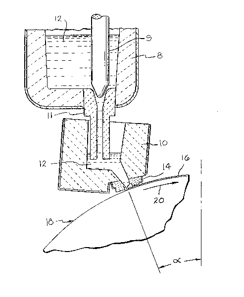
FIG. 1 is diagrammatic elevational view, partially in cross-section,
illustrating a typical apparatus of the present invention used for
continuously
casting strip;
F1G. 2 is cross-sectional view of a nozzle of the present invention.
?0
The present invention is generally illustrated in FIG. 1 wherein a casting
system is shown as including a ladle 8 which includes a stopper rod 9 for
2 5 controlling the flow of molten material 12 into a tundish or reservoir 10.
Molten
material 12 is supplied to a casting nozzle 14 for producing cast strip 16 on
a
rotating substrate 18 which is cooled and rotates in direction 20. The nozzle
is
generally located at an angle a before top dead center and typically about 5
to 90° before top dead center, and preferably about 15 to 60°.
4
'~~ ~:~~
~N i.~ i ~~ ~'~
Referring to FIG. 2, molten matorial 12 is fed to nozzle 14 through tundish
walls 10 made of a suitable high temperature refractory material which are
configured to improve the flow by providing a sloped angle A of about 15 to
90°
and preferably about 45 to 75° to the nozzle gap G9 along rear tundish
wall 10
a. The front tundish wall 10 b is generally configured at an angle of about 15
to
90° and preferably sloped from 60 to 90° and is represented by
angle ~ in FIG.
2.
Nozzle 14, made from a refractory such as boron nitride, has a rear
nozzle wall i 4a which is normally an extension of rear tundish wall 10a with
the
1 0 saws general slope. However, the flow of melt between the supply waAs and
the nozzle in the broadest terms of the invention requires that a smooth flow
at
the junction be provided and the slaps of the supply walls and nozzle walls
may
ba different. The front nozzle wall 14b is a more gradual slope with an angle
of
about 10 to 45 ° and typically about 15 to 30°. This slope is
identified as angle
1 5 B in the drawing. The combination of slopes in those walls produces a
smooth
flow of molten metal into the nozzle 14. The upper shoulder of nozzle 14b has
further bean shown to improve molten flow when the nozzle is rounded as
shown by r9. Ths rounding of the shoulders in the nozzle design also reduces
turbulence in the stream, reduces clogging in the the slat, reduces breakage
2 0 and wear of the nozzle and produces a more uniform cast strip. The slops
of
the nozzle walls also improves heat transfer from the malt to th~a nozzle area
near the substrate since the thickness is reduced and this helps to redoes
freezing.
The gap G~ between nozzle walls 14a and 14b is about 0.01 to about 0.3
2 5 inches and typically about 0.05 to 0.10 inches for casting strip of about
0.03 to
0.05 inches. The length of the slot may vary but successful casting trials
have
resulted with a length of about 0.25 to about 0.5 inches. The front nozzle
wall
S
~, '.,
a ,' :i ( J J
r.>! -'
14b has a lower rounded portion identified by r2 which improves the flow of
the
stream and strip unifiormity. The rounding ofi the nozzle portions r1 and r2
will
also reduce wear and breakage in these areas.
The distance between the lower portion ofi front wall 14b and substrate is
determined based on the balance between the casting parameters and the
desired strip thickness and identified as G~ in thre drawing. G2 is determined
by
the relationship to the size of G3 and the converging angle C used.
The distance between the substrate and nozzle is tapered with the use of
a converging nozzle until the partially solidified strip exits the nozzle. The
1 0 converging nozzle is typically at an angle G of about 1 to 15° with
respect to the
substrate 15. The opening in tho nozzle at the point ofi exit is identifiied
as Gs
and is at least the height of the desired strip thickness. The opening ofi G;~
is
less than G~ since the nozzle converges and is also less than G1. The
relationship of these gap openings in combination with the converging nozzle,
1 5 position on the wheel and melt delivery angle to the wheel will result in
an
improved casting system.
The present nozzle system provides a method and apparatus for
controlling a molten stream being removed by a rotating substrate. The pulling
action provided by the rotational speed of a substrate, such as a r~rheei,
drum or
2 0 belt, provides a flow pattern or spreading action which must be
counteracted by
a molten metal flow pattern through the casting nozzle. An increase in static
head pressure would increase the flow rate but this approach fends to increase
turbulence and cause flow patterns which have an adverse influence on surface
quality. The filow of molten material through the nozzle has an important
2 5 infiluence on the flow onto the substrate and this understanding has not
been
completely understood in the past. The present invention has found that
6
;a t'; ~ l5 ) ~ ,.~ rp
lw~ to ~'.~ r.~ ~)
restricting the flow through the nozzle 'tends to produce a flatter stream
which is
more uniform and beneficial to control of the cast strip.
The use of pressurized flow from the casting nozzle allows a greater
flexibility to increase the angle before top dead center of the substrate.
Moving
further back from the top of the substrate produces a casting process with a
longer contact time betw~en the molten material and the substrate far a given
rotational speed of the substrata. The longer contact with the substrate
increases the overall ability to extract heat during solidification.
The approach angle A has been found to improve the smoothness of the
1 0 flow exiting from the nozzle, particularly in comparison with nozzles
having a
perpendicular approach angle.
The relationship between the gaps G9, G2 and G3 is very critical to the
obtaining of improved flow and more uniform strip. When gap G1 is greater than
gap G3, the tendency for molton metal back flow is far more controllable. The
1 5 narrow stream produced at G3 is mare controlled and uniform. This gap
relationship provides a full channel in the nozzle and constant melt contact
with
the nozzle roof. The melt contact with the roof at Gs produces a more uniform
flow and a more uniform cast product. If the roof contact by the motten metal
is
intermittent, it causes fluctuations in the stream and a nonuniform cast
strip.
2 0 Restrictive flow through the nozzle tends to reduce the tendency for
stream
thinning and high flow regions in the center of the strip being cast.
Restrictive
flow also tends to minimize stream edge effects.
The benefits of a converging nozzle are shown in TABLB 1. It was
demonstrated That a converging nozzle produced a more uniform flow and
2 S forced the stream to remain flat and in contact with the rotating
substrate. A
diverging nozzle allowed the stream to roll up at the center or the edges. The
control of gap G3 is also very important to the uniformity of the stream in
the
7
i ~' % ~ i ~ ,'.) i
(~./ ~~ t-d 5.. ~3 ~ J 'J
casting operation but the converging nozzle improved the casting conditions
even for large G3 conditions. With G3 less than G1, the nozzles provided
excellent flow characteristics. There was very little spreading of the stream
and
stable flat flow was produced with excellent edge control. Rounding of the
nozzle cornors, r~ and r2, was found to reduce the formation of eddy currents
in
the stream and provide a smoother and more uniform flow condition. Sharp
corners on the inside surfaces and outer lips are subject to large pressure
drops
and strong recirculating patterns which create stress, clogging and possible
refractory wear or breakage. The prior art has rounded corners in some
1 0 designs, such as U.S.Patent No. 4,479,528 but taught a diverging nozzle
should be used to reduce turbulence and improve flaw. The present invention
has found a restrictive nozzle passageway increases uniformity ire metal flow
and the quality of the cast scrip.
Tha gap dimension far G1 is critically defined as greater than the opening
1 5 G3. Although the ranges for other nozzle designs may overlap some of the
nozzle parameters of the present invention, the specific nozzle gaps and flow
parameters have not been suggested which would produce the results of the
present nozzle design.
8
i3 ~
~d ~;~ l~~ '.a J~ I(~ l
TA~L~ 1
Angle Approach Secondary 'r=xit Angle
S ri STDG. ~Ig~, ,~j~, ~=~lv
1 15 90 0.05 +5
2* 15 90 0.05 -5
3 15 60 0.15 ~-5
1 4 i 5 60 0.05 ~5
0
15 60 0.15 -5
6* 15 60 0.05 -5
7 15 90 0.15 -5
8 15 90 0.15 ~5
1 9 45 60 0.05 -r5
S
10* 45 60 0.05 -5
11 * 45 90 0.05 -5
12 45 60 0.15 -5
13 45 90 0.15 ~r5
2 14 45 60 0.15 +5
0
45 90 0.05 +5
16 45 90 0.15 -5
2 5 *Nozzles of the invention
The results of the water model studies shown in Table 1
demonstrated the flow characteristics of the nozzles of the present invention.
A
simulated 7 foot diarneter wheel with melt head pressures varied between 3
3 0 and 16 inches and substrate speeds from 2 to 20 feet per minute were
evaluated for nozzle slots of 0.15, 0.10 and 0.05 inches (G~). The simulated
strip thickness was varied between 0.025 to 0.095 inches and was 3 inches
wide. The observations of the flow conditions supported the benefits of the
superior nozzle design of the present invention over a wide range of
conditions.
3 5 Trials 5,7,12 and 16 did not produce uniform flow conditions because the
secondary gap G3 was greater than the nozzle slot G~. The use of a converging
nozzle improved the flow compared to the diverging trials but needed to
9
~a ry :~ ~t~~~ : ) '~~ ~'
tat YI
maintain the required gap relationships to obtain the full benefits ofi the
present
invention.
INoltan low carbon steal with a fierrostatic head ofi 16 inches and a
casting temperature of about 2880° F was cast on a 7 foot diameter
copper
wheel . Tha nozzle slot ~1 was 0,10 inches. The substrate speed was varied
between 2 to 20 feat per minute to evaluate the various nozzle parameters and
their influence on flow rates and strip quality. Uniform cast strip of about 3
inches wide and about 0.035 to 0.04 inches thick was produced with the
converging nozzles ofi the present invention with the approach angle of the
1 0 delivery and casting position on the whea! according to the present
invention.
Tha nozzle designs having a gap G3 greater than ~~ did not produce the
desired flow conditions and strip quality due to the gap relationship ofi the
present invention.
Whereas the preferred embodiments have been described above for the
1 5 purpose of illustration, it will ba apparent to those skilled in the art
that
numerous modifications may be made without departing from the invention.